Hybrid Powertrain Design Using a DomainSpecific Modeling Environment Wenzhong Gao1, Sandeep Neema2, Jeff Gray3, Joseph Picone1, Sachin Porandla1, Shravana Musunuri1, J. Mathews1 embedded software is proving to be a cause of concern to automotive manufacturers. This results in an increasing difficulty in predicting interactions among various vehicle components and systems. Effective diagnosis also becomes problematic. As an example, the well-known worldwide recall in Spring 2002 of the BMW 745i was a direct result of the software failures associated with the “iDrive” control system, which controls over 700 onboard functions through embedded software. This ‘Achilles heel’ syndrome is also being experienced in contemporary design tools for automotive engineering. A face-off with modeling and simulation tools in the electronics industry has demonstrated that similar tools in the automotive domain still lack the power, sophistication and automation available to electronics designers [1]. Advances in electronic design tools have validated Moore’s law (as applied to the complexity of integrated circuits) and have helped achieve amazing standards in computing power while simultaneously decreasing costs. For designers of automotive systems to duplicate and manage similar levels of complexity, design tools that automate the low-level details of the design process need to be developed [1]. In this paper, a new design methodology is presented that merges concepts of model-based design, physics-based modeling, knowledge-based engineering, and large-scale design optimization. The rest of the paper is organized as follows: Section 2 provides an overview of the design methodology. Section 3 elaborates upon domain-specific modeling and its application to the powertrain design. Section 4 applies physics-based modeling techniques to automotive engineering design. Section 5 and Section 6 delve into the specifics of powertrain design and optimization. Finally, preliminary results and conclusions are given in section 7 and Section 8, respectively.
Abstract—State of the art design tools in automotive engineering still lack the power, sophistication, and automation of design tools that are used in the electronics industry. Widely accepted automotive powertrain design tools such as PSAT and ADVISOR still rely on manual manipulation of the design parameters for optimization. This paper presents a new methodology that merges model-based design, knowledge-based engineering, and physics-based modeling to realize large-scale design optimization. The extensible domain-specific design environment is capable of rapidly assimilating new knowledge from experts and design database. Further, it can be used to automate the management of design knowledge in a customizable manner. Introducing a design process that can handle the complexity of millions of competing constraints in an automated way will allow automotive manufacturers to reduce design time considerably. Index Terms—Domain specific modeling, GME, Hybrid powertrain, Optimization, Physics-based modeling, Bond-graphs.
I.
INTRODUCTION
From prototype design to final product manufacturing, modern automotive systems are experiencing a phenomenal growth in the deployment of new hybrid powertrain configurations and embedded controllers, and other associated technologies for disparate applications. With continuing advances in computing power and performance, it is imperative for automotive software engineering to remain connected with the innovations of new technologies and the increasing needs for better design tools. Nowadays, automotive software engineering is seen as a driving force for the innovation of new capabilities, coupled with cheaper technical solutions [1, 2]. The complexity of new designs and dependence on
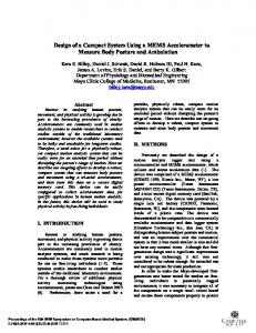
II. ARCHITECTURE OVERVIEW A domain-specific design platform that incorporates physics-based modeling, human design knowledge, optimization functions, and design databases is shown in Figure 1. This platform can be applied to a wide range of automotive design problems and can be integrated with a wide variety of industry-standard tools. One of the key objectives in the automotive design is to parameterize the design expertise of experienced automotive engineers and embed this
1
Wenzhong Gao, Jospeph Picone, Sachin Porandla, Shravana Musunuri, Jimmy Mathews are with the Center For Advanced Vehicular Systems, Mississippi State University, Starkville, MS 39759. (e-mail: {wgao,picone,skp46,musunuri,mathews}@cavs.msstate.edu ) 2 Sandeep Nema is with Institute of Software Integrated Systems, Vanderbilt University, Nashville, TN 37235. (e-mail:
[email protected]). 3 Jeff Gray is with the Department of Computer and Information Sciences, University of Alabama Birmingham, Birmingham, AL35294 (e-mail:
[email protected])
0-7803-9280-9/05/$20.00 ©2005 IEEE.
6
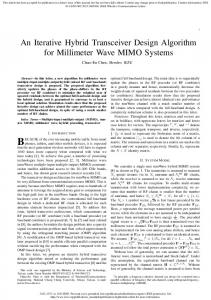
based on a separation of the problem-solving algorithm from the model and the compositionality of the model [1]. An example of the type of productivity that can be achieved from modeling, as applied to manufacturing in the automotive domain, is provided in [3]. The analysis and design techniques in traditional modeldriven development (MDD) describe the architecture and the relationships that must exist in software. Additionally, MDD also provides the capability of modeling the external interfaces to the system’s environment. However, models in such systems are loosely coupled to the actual development cycle, thereby affecting the functionality, performance, and reliability of the systems. Model Integrated Computing (MIC) [4, 5, 6] is a well-suited approach for the rapid design and implementation of systems where the software, the environment, and the integration constraints are all modeled. The resulting integrated, multiple-view models are used to configure and generate the necessary software components of the actual system and to capture the information relevant to the system under design [7, 8]. MIC tools provide the capability to model characteristics of any domain by providing customization of a modeling environment through metamodels, which describe the essential entities and connections among them. Metamodels are the specification for a domain-specific modeling environment (DSME). The DSME can then be used by domain experts to construct representations of systems in that domain. The models are typically graphical and domainspecific and are stored in a model database. The Generic Modeling Environment (GME), a flagship tool of MIC, illustrated in Figure 2, provides a solution to the longstanding requirement in software engineering, particularly in the automotive sector, for the development of modeling environments that can be easily modified and extended. The GME is a meta-configurable tool for creating and evolving domain-specific, multi-view models of large-scale engineering systems [8]. It is configurable, thus having the ability to work in different domains and is particularly useful in the design of complex systems like hybrid powertrain.
knowledge within the loop of the optimization process. Powertrain design is a target testbed to develop and refine this methodology. Domain-Specific Modeling Environment GM
Knowledge Acquisition and Representation
Search and Optimization
Performance Efficiency Cost
Design Generator
…
Design Data Analysis Goals Test
PSA PhysicsBased
Fig. 1. Design Framework
The key ingredients of this approach are: • methodologies for knowledge representation of design experience via domain-specific modeling languages (DSML) and automated capture of this information using machine learning techniques; • physics-based modeling techniques that will enable high-fidelity simulation and design using standard modeling languages such as IEEE VHDL-AMS; • knowledge-based optimization algorithms to maximize efficiency and fuel economy and minimize emissions, which are critical to the acceptance of these tools in the automotive design community. A high-degree of design automation achievable in this methodology helps in reducing both the cost and design time. Due to the large volume of production in the automotive industry, even small savings per vehicle translate into tremendous revenue for the industry [3]. This methodology also advances the fundamental understanding of how expert designers accumulate experience and make design decisions. The extensible design environment discussed in the paper will be able to assimilate additional knowledge rapidly as new designs become available. Further, it can be used to automate the management of design knowledge and can serve as a training utility for new engineers. The following sections briefly elaborate the key technology components that are employed in this application.
Model Editing Window
Model Browser
III. DOMAIN SPECIFIC MODELING ENVIRONMENTS The automotive sector was one of the first to adopt modelbased design technology on a broad scale. Model-based design provides a good basis for addressing system complexity and other problems, primarily because they are
Part Browser
Fig.2. The Generic Modeling Environment
7
Attribute Browser
powertrain. The following sections outline key characteristics of powertrain design that can be improved through a configurable modeling tool like the GME.
In addition to the model design, the embedded software also could be modeled in the GME. Figure 3 shows the modeling of the Electronic Throttle Controller (ETC) software in the GME. This gives a clear indication of the capability of the GME to model an application as well as to model the software used in that particular model.
IV. PHYSICS-BASED MODELING Existing powertrain design tools [10] are based on experiential models, such as look-up tables, which use idealized assumptions and limited experimental data. The accuracy of these tools may not be good enough for vehicles operating under extreme conditions. On the other hand, the designs may lead to components or systems beyond physical limitations. To make design optimization effective, models must be tied closely to the underlying physics through a link such as a lumped-coefficient differential equation or some digital equivalent computer model. Only then can it be assured that the subset of physically-realizable models will be searched and that real-world constraints will guide the design to a meaningful optimum. In physics-based modeling, the state variables of a component or subsystem are modeled according to the physical laws representing the underlying principles. The resulting model is a function of device parameters, physical constants, and variables. Such physicsbased models can facilitate high fidelity simulations for dynamics at different time scales. In our study, two physics-based modeling techniques – Resistive Companion (RC) [11] modeling and Bond Graph (BG) [12] modeling – are explored. The RC method originates from electrical engineering, while the BG originates from mechanical engineering. Both methods are suitable for multidisciplinary modeling applications and together could be used for efficiently modeling and designing a complex system like hybrid powertrain. The RC method has been used successfully in a number of industry-standard electronic design tools such as SPICE and SABER. Recently, it has also been applied in the Virtual Test Bed [11], which is being recognized as the leading software for prototyping of large-scale, multi-technical dynamic systems such as those found in electric ships. Using the Resistive Companion Form (RCF) modeling technique [11], we can obtain high-fidelity physics-based models of each component in modular format. These models can be seamlessly integrated to build a system simulation model suitable for design. Just as a physical device is connected to other devices to form a system, the device can be modeled as a block with a number of terminals through which it can be interconnected to other component models, as shown in Figure 4.
Fig.3. The Electronic Throttle Controller modeled in GME
Our initial work has adopted the GME as a key technology to support our vision of improved powertrain design. A domain-specific modeling language is being constructed to address the special features needed for powertrain design and integration with physics-based modeling techniques, machinelearning techniques, and other tool suites such as optimization tools and SABER. Modern modeling tools, such as the GME, are characterized by a greater flexibility of reuse and flexibility to support the modeling of physical entities in software. In the powertrain design, GME allows the exploitation of a range of possibilities offered by the hybridization of powertrains, unlike a majority of simulation packages that are based on fixed powertrain layouts. In addition, the GME also provides the capability of setting constraints on the models, if required, which prevents any erroneous design. All these advanced functionalities form the crux of an attempt to develop a set of robust, multiconfigurable tools for “Intelligent Powertrain Design”. It is also possible to co-simulate the design process of a system with other design software like MATLAB/SIMULINK, etc. The model interpreter for the model developed in GME can generate a Matlab script file, which then could be included in the MATLAB/SIMULINK environment. For example, the execution of this script file can generate Simulink–Stateflow models [9]. Any changes that are needed to be made in the design process could be made easily in GME. All the above features could be used in an efficient way in the design and modeling of a complex system like hybrid
Fig.4. Physics-Based Resistive Companion Form Modeling Technique
8
developing design tools for analog based complex engineering systems like automotive powertrains. However, unlike digital design, analog design is less systematic, more heuristic and knowledge-intensive in nature. This makes the powertrain design more challenging when compared to digital circuit design.
On the other hand, in Bond Graph modeling, a physical system is represented by a collection of components that interact with each other through energy ports [12]. It is a powerful tool for modeling engineering systems, especially when different physical domains are involved. The physical structural information is conserved. BG uses analogous power and energy variables in all domains, but allows the special features of the separate fields to be represented. The only physical variables required to represent all energetic systems are power variables (effort (e) & flow (f)) and energy variables (momentum p(t) and displacement q(t)). There are several BG-based commercial software packages for modeling and simulation of dynamic systems (e.g., CAMP-G [13] and 20-Sim [14]). BG method has also been applied to the modeling of hybrid vehicle powertrain [15].
VI. DESIGN OPTIMIZATION Optimization is an area receiving much attention in automotive design [16, 17]. The availability of many configurations, control strategies, and design variables necessitates the use of mathematical modeling and design optimization to find the best overall design. Thus, the optimization process becomes a problem of large-scale multiobjectives (e.g., maximum fuel economy, minimum emissions, minimum cost). There are two types of optimization methods that can be applied to automotive design: equation-based and simulation-based. The equationbased method is not practical due to the difficulty in obtaining analytical objective functions in terms of the design variables. On the other hand, with the improved computation power, advanced numerical algorithms can be looped with a simulation model to achieve simulation-based design optimization. Although classical numerical optimization techniques can be used, statistical methods (e.g., simulated annealing and genetic algorithms) seem more effective in avoiding local minima in the search-space. Optimization techniques have been applied in the design of power converters, which are critical functional components of any hybrid powertrain. Various optimization tools have been developed for meeting certain requirements. For example, a design optimization tool that minimizes materials cost for a boost converter was developed based on a genetic algorithm [18]. This tool takes into account the design specification, physical limitations, and operational safety of the device. Another optimization tool based on CAD is used for the design of automotive DC/DC converters [19]. In this tool, the objective function is a weighted sum of component volume, weight, and cost. A Monte Carlo search method and expert system are used in the selection process of the components. A large number of iterations are necessary before an optimum design is reached. Unfortunately, this tool is very timeconsuming and there is no guarantee that an optimum solution will be found. Knowledge-based optimization has also been applied to the design of power converters. An expert system with a design knowledge base and automated computer-aided optimization was implemented in a CAD-Tool for the design of switched mode power supplies [20]. The expert system shell CLIPS was used. A knowledge base is used to select the best power supply topology according to the given design specification. A sub-knowledge base is used to select components based on the target volume, cost, and efficiency of the design. The
V. POWERTRAIN DESIGN Hybrid powertrain design depends on the mission and performance requirements of a vehicle and its application. Design flexibility for hybrid powertrains requires evaluation of a large number of options and complex non-linearities that exist among various components. It is difficult for designers to reach an optimum tradeoff among various design criteria (e.g., size, efficiency, cost, weight, and volume) using a manual tool. Current powertrain design tools are not suitable for such optimal design and do not facilitate the reuse of expert knowledge. These factors, along with the large design space, necessitates the use of novel automated search techniques for achieving the near optimal design. To address these challenges in powertrain design, domain knowledge extracted from experienced designers along with the standard optimization techniques have to be integrated into an extensible computer-aided design platform. This combination of large-scale design optimization and knowledge–based engineering will result in a unique powerful intelligent design software package for hybrid electric vehicle powertrains. The immediate benefits are the improvement of the design in terms of cost and performance and the reduction of the number of design iterations. The desired goal can be achieved by employing methodologies for knowledge representation of design experience using a DSME and automated capture of knowledge using machine-learning techniques. The key areas in defining design methodologies are physical design, simulation/verification, synthesis, and testing. The main reason for the success of automated engineering design is that a higher-level of abstraction can be established so that all the device-level and process-level details can be shielded from the higher-level design. The electronic design automation (EDA) employed in the design of analog and digital circuit is an example for such a design methodology. The achievements of EDA can serve as a model for
9
knowledge base can also assist in the selection of the appropriate control scheme. A classification of the optimization algorithms (gradientbased and non-gradient/derivative-free) used in a hybrid powertrain design environment is given in [21]. The gradientbased algorithms (e.g., Sequential Quadratic Programming [22]) works well for smooth, continuous functions, but often fail miserably for noisy, discontinuous functions because of the wrongly calculated gradients. Derivative-free algorithms (e.g., DIRECT [23] and COMPLEX [24]) can be used to avoid the gradient calculation problem. DIRECT (DIviding RECTangles) is an optimization algorithm designed to search aggressively for global minima of a real valued objective function over a bound-constrained domain without using derivative information [25]. Many toolboxes using the above mentioned routines are applied to analyze the hybrid electric vehicle optimization process in [10]. Algorithms based on the Expectation–Maximization algorithm are developed and shown in [26], which can significantly improve the convergence criteria compared to other algorithms. Based on our initial investigation, DIRECT and Expectation– Maximization algorithms are to be used in our powertrain design tool because these algorithms facilitate a knowledgebased search and simulation-based optimization.
12
Voltage across Inductor
10
8
6
4
2
0 1
6
11
16
21
26
31
36
41
46
51
56
61
66
71
76 81
86
91
96
Time in microseconds
Fig.6. Voltage across Inductor
As an illustration of the modeling using Bond Graph technique, a Bond Graph metamodeling environment has also been created in GME and a DC motor is modeled as an application example, illustrated in Figure 7.
VII. PRELIMINARY RESULTS As a first step in the powertrain design, a metamodeling environment has been developed in GME for solving an electrical circuit involving basic elements like source, resistor, inductor, and capacitor in any circuit configuration. RCF technique was used in the dynamic modeling. The following figures show an application model developed in GME from this meta-model and the simulation results. The numerical results obtained are verified to be correct. Fig.7. DC Motor Modeling using Bond Graph in GME
12
1k
The RCF and bond graph techniques could be used efficiently in the design and modeling of other linear and nonlinear multi-domain components and systems in GME. The hybrid powertrain, which is a complex combination of linear and non-linear elements and components, could be modeled in GME using the above techniques. The hybrid powertrain configuration metamodeling environment created in GME allows for the incorporation of domain expert’s knowledge and automatic check of the design constraints. The meta-model developed defines three aspects or domains (electrical, mechanical, power train) in which the vehicle design can be visualised with appropriate constraints set on each component. As an application example of this environment, models of series hybrid powertrain and parallel hybrid powertrain are developed, and are shown in powertrain aspect as illustrated in Figure 8 and Figure 9.
1m
1 ohm
Fig.5. R-L Circuit in GME
10
advanced modeling and design strongly suggest the success of this design methodology. REFERENCES [1] [2] [3] [4]
[5] Fig.8. Parallel Hybrid Powertrain design in GME [6] [7] [8]
[9] [10]
[11]
Fig.9. Series Hybrid Powertrain design in GME
[12]
It should be noted that this metamodeling environment allows for innovative powertrain configuration design, while setting constraints to maintain a physically realizable design. In our on-going effort, a new metamodeling environment that integrates the configuration of powertrain, bond-graph modeling together with optimization algorithm will be created. This domain-specific modeling environment will be used for hybrid powertrain design and analysis.
[13] [14] [15] [16] [17]
VIII. CONCLUSIONS
[18]
This paper addresses the issues facing contemporary automotive engineering design tools. It presents a new methodology for design automation by integrating modelbased design, physics-based modeling, knowledge-based engineering, and large-scale design optimization in a domainspecific modeling environment. Such a design tool has the potential to bring significant cost savings, performance enhancement, and design time reduction for hybrid powertrains. Though the design of hybrid powertrain using the CDSME principles in GME is still in progress, the preliminary results and the proven capability of GME for
[19] [20]
[21]
11
P. Struss and C. Price, “Model-Based Systems in the Automotive Industry,” AI Magazine, Winter 2004, 24(4), pp. 17-34 M. Broy, “Challenges in Automotive Software Engineering: From Demands to Solutions,” EmSys Summer School, Salzburg, Austria, July, 2003. E.Long , A.Misra , J.Sztipanovits, “Increasing production at Saturn,”, IEEE Computer, August 1998 , pp. 35-43. G. Karsai, M. Maroti, Á. Lédeczi, J.Gray, and J. Sztipanovits, “Composition and Cloning in Modeling and Meta-Modeling,” IEEE Transactions on Control System Technology (special issue on Computer Automated Multi-Paradigm Modeling), vol. 12, no. 2, March 2004, pp. 263-278. J. Sztipanovits, “Generative Programming for Embedded Systems,” Keynote Address: Generative Programming and Component Engineering (GPCE), LNCS 2487, Pittsburgh, Pennsylvania, October 2002, pp. 32-49 J. Sztipanovits and G. Karsai, “Model-integrated Computing,” IEEE Computer, 30(4), April 1997, pp. 110-111. Á. Lédeczi, A. Bakay, M. Maroti, P. Volgyesi, G. Nordstrom, J. Sprinkle, and G. Karsai, “Composing Domain-Specific Design Environments,” IEEE Computer, November 2001, pp. 44-51. S. Neema, T. Bapty, J. Gray, and A. Gokhale, “Generators for Synthesis of QoS Adaptation in Distributed Real-Time Embedded Systems,” Generative Programming and Component Engineering (GPCE), LNCS 2487, Pittsburgh, Pennsylvania, October 2002, pp. 236-251. D. Vashishtha , “ Modeling and Simulation of Large Scale Real Time Embedded SYSTEMS,” Master’s Thesis , Electrical Engineering , Vanderbilt University , May 2004 ,pp.35-37. T. Markel, A. Brooker, T. Hendricks, V. Johnson, K. Kelly, B. Kramer, M. O’Keefe, S. Sprik and K. Wipke, “ADVISOR: A Systems Analysis Tool for Advanced Vehicle Modeling,” Journal of Power Sources, 110(2), August 2002, pp. 255-266. W. Gao, E. Solodovnik, and R. Dougal, “Symbolically-aided model development for an induction machine in Virtual Test Bed,” IEEE Transactions on Energy Conversion, vol. 19, no. 1, March, 2004, pp125135. D. Karnopp, D. L. Margolis, and R. C. Rosenberg, “System Dynamics: Modeling and simulation of mechatronic systems”, John Wiley & Sons, 2000. CAMP-G [Online]. Available: http://www.20sim.com/ Bondgraphs [Online] . Available: http://www.bondgraph.com/ M. Filippa, C. Mi, and J. Shen, “Modeling of a hybrid vehicle powertrain test cell using bond graphs,” IEEE Transactions on Vehicular Technology, vol. 54, no. 3, May, 2005. T. Moore, “HEV Control Strategy: Implications of Performance Criteria, System Configuration and Design, and Component Selection,” Proc. of American Control Conference, vol. 1, 4 - 6 June 1997, pp. 679 - 683. L. Guzzella, and A. Amstutz, “CAE Tools for Quasi-Static Modeling and Optimization of Hybrid Powertrains,” IEEE Trans. on Veh. Technology, vol. 48, no. 6, Nov. 1999, pp. 1762-1769. S. Busquets-Monge, G. Soremekun, E. Hertz, C. Crebier, S. Ragon, D. Boroyevich, Z. Gordal, M. Arpilliere, and D. Lindner, “Power Converter Design Optimization,” IEEE Industry Applications Magazine, vol. 10, no. 1, pp. 32-39, Jan. 2004. T. Neugebauer, and D. Perreault, “Computer-Aided Optimization of DC/DC Converters for Automotive Applications,” IEEE Trans. on Power Electronics, vol. 18, no. 3, May 2003, pp. 775-783. N. Froehleke, D. Hahm, H. Mundinger, H. Njiende, P. Wallmeier, and H. Puder, “CAE-Tool for Optimizing Development of Switched Mode Power Supplies,” Proc. IEEE Applied Power Electronics Conference and Exposition, vol. 2, 4-8 March 2001, pp. 752-758. R. Fellini, N. Michelena, P.Papalambros, and M. Sasena, “Optimal Design of Automotive Hybrid Powertrain Systems,” Proceedings of EcoDesign 99 - First Int. Symp. On Environmentally Conscious Design
[22] [23] [24]
[25]
[26]
and Inverse Manufacturing (H. Yoshikawa et al., eds.), Tokyo, Japan, February 1999, pp. 400-405. K. Schittkowski, “NLQPL: A FORTRAN-Subroutine Solving Constrained Nonlinear Programming Problems,” Annals of Operations Research, vol. 5, pp. 485-500, 1995. M. Bjorkman, and K. Holmstrom, “Global Optimization Using the DIRECT Algorithm in Matlab,” Advanced Modeling and Optimization, vol. 1, no. 2, 1999. M. J. Box, “A New Method of Constrained Optimization and a Comparison with Other Methods,” Imperial Chemical Industries Limited, Central Instrument Research Laboratory, Bozedown House, Whitchurch Hill, Nr. Reading, Berks, 1965. S. Cox, R. Haftka, C. Baker, B. Grossman, W. Mason and L. Watson, “A Comparison of Global Optimizing Methods for the Design of a High-Speed Civil Transport,” Journal of Global Optimization, 21(4), 2001, pp. 415-433. R.Salakhutdinov, S. Roweis, Z. Ghahramani, “Optimization with EM and Expectation-Conjugate-Method,” International Conference on Machine Learning, Washington, DC, August 2003, pp. 672-679.
12