AbstractâExisting routing protocols for sensor networks ei- .... S4 [10], is designed to provide small stretch and state in order to .... on our real-world deployment.
1
Hydro: A Hybrid Routing Protocol for Low-Power and Lossy Networks Stephen Dawson-Haggerty, Arsalan Tavakoli, and David Culler Computer Science Division University of California, Berkeley {stevedh,arsalan,culler}@cs.berkeley.edu
Abstract—Existing routing protocols for sensor networks either exclusively focus on collection-based traffic, or optimize for point-to-point traffic in a homogeneous network. As these networks become more general, a mix of these workloads in a heterogeneous setting is expected, while still abiding by the resource constraints of low-power and lossy networks (L2Ns). Our design leverages the predominantly two-tiered topology of L2N deployments, with capable border routers supplementing resource-starved in-network nodes, and optimizes for the typical traffic workloads consisting mainly of collection based traffic with specific instances of point-to-point traffic. We present Hydro, a hybrid routing protocol that combines local agility with centralized control. In-network nodes use distributed DAG formation to provide default routes to border routers, concurrently forming the foundation for triangle pointto-point routing. Border Routers build a global, but typically incomplete, view of the network using topology reports received from in-network nodes, and subsequently install optimized routes in the network for active point-to-point flows. Building on the vast existing literature on distributed DAG formation in L2Ns and centralized routing in large-scale networks, our contribution lies in the merging of these ideas in the form of a routing protocol that addresses the needs of L2Ns while remaining grounded in their inherent constraints. Evaluations across testbeds and deployments demonstrate the performance and functionality of Hydro across a variety of workloads and network conditions.
I. I NTRODUCTION Data collection represents a significant fraction of network traffic in many monitoring applications, as has been welldocumented in the literature [14], [6], [15]. In these systems, in-network nodes gather sensor data locally and either trickle their readings frequently or send bulk data sets periodically to a remote server with the border routers acting as data sinks. Since most applications employ some form of collection, it is critical to optimize collection as a basic network primitive. However, point-to-point traffic also occurs, especially since these networks are now embracing IP. Collection and dissemination alone are insufficient, since they lead to inefficient application modalities such as flooding the entire network to deliver a command to a single node. In many cases, point-to-point routing would be used to initiate data transfer, send end-to-end acknowledgements like in TCP and Flush, or for carrying out infrequent network diagnostics with ping and traceroute. In some cases, traffic flows exist between a “root” node and some other node in a network. In other cases, point-to-point flows exist between
arbitrary nodes in the network, like a control path between a light switch and light bulb. A successful point-to-point routing protocol will make few demands on nodes in the first case and will make demands proportional to some measure of the workload (e.g. number of flows, nodes, or neighbors) in the second case. The key insight underlying this work is that while point-topoint routing is becoming more important, the space, time, and message overhead of point-to-point routing must be proportional to its often minor yet critical usage in practice. In other words, application developers are willing to pay for point-topoint routing only if its cost is negligible when it goes unused and is proportional to the degree of point-to-point traffic when it does get used. Unfortunately, existing point-to-point routing protocols like S4, BVR, and DYMO do not satisfy this loadproportionality. This fact may be one reason they are relatively unused in practice, especially since a collection protocol may still be necessary and run in parallel. In order to meet the requirements of robust collection, point-to-point communication, and low footprint, we present Hydro, a hybrid routing protocol for L2Ns that provides both centralized control and local agility. Hydro uses a distributed algorithm to form a DAG for routing data from in-network nodes to border routers, allowing nodes to maintain multiple options that are ranked through data-driven link estimation. Nodes piggyback topology reports on periodic collection traffic, allowing border routers to build and maintain a global view of the topology. The DAG provides basic triangle pointto-point routing by allowing nodes to forward packets to a border router, which subsequently source routes them to the appropriate destination. Hydro builds on prior work by Hui [5] by adding a centralized optimization in which border routers insert routing table entries at the appropriate nodes, reducing the transmission stretch between communicating endpoints without the need for excessive state or complexity at the nodes. II. BACKGROUND Routing has been an integral part of L2Ns since their emergence, as data and commands had to be relayed between nodes. Initially, as many of the deployments focused on various types of monitoring, the predominant communication paradigm was Collection-Oriented, or many-to-one routing. By association Dissemination-Oriented, or one-to-many, routing also emerged because of the need to send commands to the nodes (e.g. for time synchronization).
2
MintRoute and its successor, CTP [16], [3] are gradientbased collection protocols. CTP developed a more accurate link estimator, in which control and data traffic were used to inform link estimates. TSMP [13], incorporated into the WirelessHART standard, is a well-established industry approach that includes centralize scheduling of channel resources to achieve predictable latencies. However, although little technical data is available, it operates at the link-layer, using channel hopping, and does not provide any routing capabilities specified in publicly available documentation. Its tight scheduling of media accesses differs significantly from the functionality of our border routers, which contain only soft state and are relatively asynchronous. Hui presented a complete IPv6 network architecture for L2Ns, which includes a low power link along with network and transport layers adapted to the unique characteristics of these networks [5]. This work adapted collection to the IP architecture by conceptualizing it as choosing an IP default route. It also provided unicast capabilities by allowing a controller to efficiently communicate with individual nodes by source routing the packet, forming the basis for triangle routing of intra-network traffic. However, such an approach also incurs unnecessarily high stretch and bottleneck links around the controller. This basic design represents the leading edge of collection research, and formed Hydro’s basic template; we extend it with optimizations for point-to-point traffic. BVR [4] was a geographical location-based routing protocol for L2Ns. A set of landmark beacons are selected whose identity is known by all nodes in the network. Every node is given a virtual coordinate, which is the vector of distances to all beacons in the network. When a node wants to send a packet to a destination node, it greedily forwards the packet along routes that move it closer to the destination. S4 [10], is designed to provide small stretch and state in order to enable scalable routing. It utilizes a modified compact routing algorithm tailored for L2Ns. S4 has a theoretical worst case routing stretch of 3, although published results indicate √ an average routing stretch of 1.2 while maintaining O( N ) state. Deploying S4 would require also designing a distributed directory service, and the protocol does not optimize for the common workload where most traffic is destined towards an egress point; unlike S4’s homogeneous network, Hydro starts with optimizing collection and emphasizing heterogeneity. AODV [12] uses flooded RREQ messages to discover paths to destinations on demand, with intermediate nodes creating hop-by-hop entries for bidirectional flows. DSR [7] is also an on-demand routing protocol, but uses source routing to route packets. OLSR [2] is a link state algorithm that uses multipoint relays to reduce the flood of link-state advertisements. 802.11s, a draft mesh routing standard uses a variant of AODV called AODV-RM for intra-subnet point-to-point communication, but optimizes for an access network’s workload by proactively building a routing tree towards egress points [1]. These and other protocols provide point-to-point routing capabilities in wireless networks. Both on-demand and linkstate based solutions exist, but the focus is on providing reliable any-to-any delivery in networks with mobile nodes that are resource rich. Consequently, most of these protocols
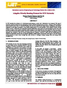
have large control traffic and/or state requirements. III. H YDRO D ESIGN AND O PERATION Hydro’s design is a marriage of centralized and distributed mechanisms: low-power nodes form and maintain a distributed DAG that provides them with a set of default routes for communicating with border routers. These border routers maintain a global view of the network using topology reports received from each of the nodes, and subsequently install optimized point-to-point routes within the network. These three mechanisms of distributed DAG formation, global topology formation, and route install form the primitives for Hydro’s operation, and are shown in figure 1. A. Distributed DAG formation Most communication in L2Ns is data generated by network nodes being routed to data sinks. In Hydro, border routers provide egress connectivity beyond the L2N to these data sinks and other internet hosts. The distributed DAG provides a locally-maintained mechanism for optimizing the collection workload. Therefore, the first primitive Hydro provides is a reliable route towards a border router: a Default Route Table, made of a list of entries, each containing the link-layer address of a node in the direction of a border router. Each solid arrow in figure 1 corresponds to an entry in a node’s Default Route Table. Once a neighbor has been inserted into the Default Route Table, the node will begin to maintain statistics about the link-layer packet success rates to help it evaluate the quality of that link. Existing collection-based protocols demonstrated that providing multiple routes to a given destination significantly improves reliability in L2Ns [3], [5]. Hydro’s Default Route Table is an ordered list of next hop addresses for communicating with border routers. Each default route entry contains the address of the next-hop in the path, the route cost advertised by the next-hop, the link cost estimate for communicating with the next-hop (and the corresponding confidence), and the advertised willingness. B. Global Topology Construction The second primitive Hydro requires is the collection of topology information from the network: in order to execute its duties as a central point of control, a border router must build a global view of the topology. However, this task is complicated by multiple factors: restrictions on control traffic make it impractical for the nodes to send their complete linkstate to the border router; furthermore, memory constraints prevent nodes from even maintaining a list of all neighbors, making creation of the complete global topology impossible. In Hydro, each node in the network creates Topology Reports to be sent to a border router. Topology reports contain only the top few “mature” entries in the Default Route Table. In addition, Hydro allows nodes to optionally insert Node Attributes in topology reports. These Node Attributes are application specific, and can be static (e.g. installed memory or power source), or dynamic (e.g. energy left or queue length), to enable more complex routing policies.
3
Fig. 1. Overview of Hydro containing all three primitives. The distributed DAG, represented by solid arrows, is maintained using the Default Route Table and points towards border routers. Topology collection uses piggybacked updates to allow border routers to maintain the Link State Database. Finally, installed routes are stored in per-node Flow Tables.
Topology reports are sent to a border router periodically using a default route; they are opportunistically piggybacked on data traffic whenever an application generates sufficiently frequent traffic. The unpacked datagram in figure 1 shows how topology information is added to data traffic using an optional extension header; using this mechanism, the overhead is only incurred on packets actually containing topology updates. The border router aggregates these topology reports to create a global view of the topology, known as the Link State Database. Figure 1 shows a partial view of the LSDB maintained by controller 1: for instance, the link from 5 to 2, being reported in the exploded packet is present in the database with cost 2.5. While this view does not include all links in the physical network, it is a subset of high-quality, bidirectional links with accurate link cost estimates. C. Centralized Route Installation The combination of distributed DAG formation and a global topology database enables point-to-point communication through triangle routing. The final Hydro primitive allows state to be installed in the network to optimize active flows. A border router uses Route Installs to update a node’s Flow Table. When a node receives a Route Install, it inserts or updates an entry in the Flow Table. Each Route Install has two parts: • Flow Match: The criteria used to determine whether a given packet matches a flow table entry. By default Hydro uses the packet destination, but more complex flow matches based on additional fields such as the packet source, traffic type, or flow label are possible. • Flow Path: The actual route that matching packets use. Hydro stores the complete path to the destination used in a source routing header The policy for when routes should be installed may either be a default policy, or optimized for specific workloads. By default, Hydro installs routes the first time they are used.
D. Forwarding Both nodes and border routers function as routers and forward packets. Hydro’s packet forwarding policy is different for each. 1) Node Forwarding: The routing layer on a node contains two tables with forwarding information. The Default Route Table maintains state about neighbors which are closer to a border router then that node. The Flow Table maintains routes to other in-network notes which has been installed by a border router. In order to forward packets, in-network nodes take the following actions: 1) Source Route: If a packet contains a valid source route, the node forwards the packet to the next router in the sequence. 2) Flow Table Entry: If a matching entry exists in the Flow Table, then it is used to forward the packet on to the destination. 3) Default Route: If neither a source route nor flow entry is available, packets are forwarded along a default route to a border router. E. Multiple Border Routers A single border router creates a single point of failure, either due to failure of the border router itself, or because of media congestion around that one device. Furthermore, scalability and deep paths also become a concern in larger networks. To alleviate such concerns, Hydro provides a mechanism for installing additional border routers. All border routers are exact replicas, each maintaining the same a global topology view. The border routers are connected network using separate interfaces from those used to communicate with the L2N subnet: typically this back-haul link is either an Ethernet or an 802.11 mesh. This use of multiple border routers, if properly located and deployed can help manage the depth of the network as well as
4
the volume of traffic congesting bottleneck links to a border router. We examine this benefit empirically on a large testbed in section IV. F. State Management The three tables maintained by Hydro are shown in figure 1; their contents have been discussed in previous sections. First, The Default Route Table is used to maintain a stable backchannel to a border router; its consistency is maintained by using a standard tree-formation protocol. When inconsistencies are detected, broadcasts are started to resolve them. The second table, the Link State Database is maintained at all border routers by processing topology reports. Since nodes are required to periodically send these updates, a border router which fails will recover merely by listening to updates for same amount of time as the slowest topology update. The final table is the Route Install Table: it contains routes installed based on the Link State Database of a border router at some point in time. It is also not proactively maintained: when a link which is part of an installed route fails, the packet is forwarded to a border router. In addition to removing the link from the LSDB after a small number of failures, the border router will generate a “Route Uninstall” message so that the node router does not continue to use the same erroneous route.
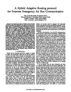
B. Implementation Details Our implementation of Hydro is built on top of a lowpower IPv6 stack using 6loWPAN [11] and the TinyOS 2 operating sytem [8]; it forms the core of the routing protocol distributed with blip, the 6loWPAN/IPv6 stack developed at Berkeley and distributed with TinyOS. Unless otherwise stated, our implementation uses the default settings highlighted in Section III. Border Routers exist in two forms: either a normal PC with a connected node for interfacing with the L2N, or an embedded Linux device with an integrated 802.15.4 radio. C. Distributed DAG Formation The distributed DAG is critical to Hydro’s functionality. To assess this reliability, we examine the performance of Hydro on our real-world deployment. The workload consisted of nodes transmitting data every 1 minute to an external server. Figure 2 provides a histogram of the packet delivery ratio (PDR) observed across three days on our real deployment. The nodes are deployed in a very wi-fi intensive environment, leading to a slight degradation in performance during the work-week. Nonetheless, we still see that the median PDR is 99.4% on a Saturday, and 98.4% on a Monday, reinforcing the key assertion that the distributed DAG effectively provides a reliable backchannel to the border router.
IV. E VALUATION This section evaluates the performance of Hydro on several key metrics across multiple networks. In one application, we evaluate the performance of 57 nodes running Hydro for over six months in a real deployment of wall-plug meters [6]. On two experimental testbeds, we evaluate Hydro’s scalability, performance, and resilience across a range of workloads and failure conditions. A. Methodology We use two testbeds and a real deployment to evaluate Hydro. Testbed A is a ceiling-mounted network of 48 nodes across a single floor and a network diameter of 3-5 hops, depending on environmental factors. Testbed B consists of a network of 125 nodes spread across three floors, with a diameter of 7-9 hops. Both testbeds are equipped with wired backchannels, which we use to collect packet traces that allow us to track the progress of packets through the network. The real deployment consists of 49 nodes spread across four floors of an office building, with the nodes placed in various locations, such as under desks, inside a refrigerator, or on the ceiling. An additional eight nodes are installed in a remote residential environment, resulting in a total deployment size of 57 nodes. For the baseline workload in these experiments, all nodes report data to a border router every 30 seconds (with no other form of traffic). We define a flow to be traffic between a source / destination pair, and in our experiments, we use ICMP ping messages, separated by 2 seconds for multi-packet flows. In addition, all experiments are given time to bootstrap the network topology formation, except as noted.
Fig. 2. CDF of collection packet delivery ratio observed over three days in a real-world deployment.
D. Centralized Route Installation To evalute the impact of the centralized optimization of installing routes, we compare our protocol to itself with route installation disabled, so that all packets are forced to use a default route through the border router. Our experiment begins with 5 concurrent bidirectional flows of 50 packets each and increases to 23 bidirectional flows, enlisting all but two nodes in the network as traffic endpoints. Node Flow Tables are cleared after each trial. Figure 3 shows the result of the experiment after 5 trials, each using different pairs. Error-bars signify standard deviation. When route installs are active, the packet delivery ratio remains above 98.7%, as seen in the top of Figure 3 indicating at a high level that the protocol performs “well,”
5
0.9 0.85 0.8 0.75
Centralized Triangle
DAG Control Packets Route Install (per Node) Trans (per Flow)
0.7 4
6
8
10
12
14
16
18
20
22
24
4
6
8
10
12
14
16
18
20
22
24
4
6
8
10
12
14
16
18
20
22
24
15 10 5 0
0.8 0.6 0.4
Figure 4 demonstrates that the packet delivery ratio remains near 100% until near the end of the experiment. Added route install traffic is clearly visible after a route has been broken. At the same time, the DAG maintainence traffic works in the background to maintain reachablity to the controller. Nodes use cached default routes until approximately 1500 seconds, when some nodes must begin seeking out new default routes and therefore triggering additional DAG control traffic. At the end of the experiment, the delivery rate drops to zero as the network becomes partitioned. We note that this indicates that Hydro is able to quickly respond to broken links in the network, as the overall delivery rate remains close to 100%.
0.2 0 1
Number of Concurrent Flows
Fig. 3. Packet delivery and control traffic rates as a function of the number of concurrent flows, with (centralize) and without (triangle) the route install optimization.
Packet Delivery Percentage
Packet Delivery Percentage
1 0.95
0.95
0.9
0.85
the forwarding engine is “reliable,” and that it supports a reasonably large amount of traffic. The lower two graphs in Figure 3 contain the total number of centralized control transmissions per flow, and the total DAG maintainence traffic per node per minute. These generally show a low level of traffic. The kink in the center graph was caused by the protocol reacting to a link failure. Centralized systems are often criticized for being too slow to detect and react to remote events. It is important that the optimization we introduced does not break in the case of node and link failures. Therefore, we next turn our attention to Hydro’s robustness to node failures. Figure 4 examines the performance of a single bidirectional flow as all other nodes in the network are failed. The state of the system is constantly probed by a single bidirectional flow with traffic sent once per second. Every four minutes, four random nodes are removed with the experiment ending when 44 nodes (out of 48 in Testbed A) are killed, leaving the network partitioned. The vertical lines in the graph indicate the points at which nodes were killed.
Packet Delivery Percentage
1
0.8
0.6
0.4
0.2
DAG Control Packets Route Install (per Node) Trans (per Flow)
0.8 0
500
1000
1500
2000
2500
3000
0
500
1000
1500
2000
2500
3000
0
500
1000
1500
2000
2500
3000
10
5
0
2 1.5 1 0.5 0
Time
Fig. 5. Packet delivery ratio and control traffic statistics for multiple flows amidst node failures. Approximatly half the nodes are involved in a flow, and the rest progressively fail until only the active nodes remain. Four nodes are removed at each vertical line.
To ensure that our result was not biased by our selection of a particular pair of endpoints, we repeat the experiment with a larger number of concurrent flows. Figure 5 shows the same view of the data: at a high level, it appears that Hydro still responds well to the network failures. We see an interesting spike in control traffic around 1000 seconds into the experiment: at this point we have removed approximately 1/3 of the network, and the DAG forms a brief loop, which persists for several minutes before the DAG re-forms and success rates return to near 100%. The key result of these two experiments is that Hydro’s mechanism to both install and expire state in the network continues to work even in the face of substantial failure.
DAG Control Packets Route Install (per Node) Trans (per Flow)
0 0
500
1000
1500
2000
2500
3000
3500
4
E. Footprint and Overhead Analysis
3 2 1 0 0
500
1000
1500
0
500
1000
1500
2000
2500
3000
3500
2000
2500
3000
3500
6 4 2 0
Time
Fig. 4. Packet delivery ratio and control traffic statistics for a single flow amidst node failures: each vertical line indicates that four nodes failed, until finally only four nodes remain and the network is partitioned.
The previous section primarily focused on the performance of Hydro, namely stretch and packet delivery ratio. In this section we examine state requirements and control overhead, as well as Hydro’s code and memory footprint. Table I breaks out the RAM and ROM sizes of the networking components in our system stack. While all are critical to Hydro’s operation, all of the protocol’s logic is embedded in Hydro Router, which is only 5K of code, and 524 Bytes of RAM including all routing state for six individual flows as well as 210 Bytes of other static data. Removing the route
6
installation functionalty and providing only triangle routing reduces the code size by approximately 2kB. Component CC2420 Driver 6lowpan Adaptation IP Forwarding Engine Hydro Router ICMP Engine UDP Transport Layer
ROM Size 5390 1310 2760 5172 1590 662
RAM Size 237 0 188 524 34 8
TABLE I C ODE AND MEMORY FOOTPRINT.
Top. Report Src. Route Route Inst. Solicit. Adver.
Overhead (bytes) 4+(4·Neigh)+NA 4+(2·Hops) 1 + (2·Hops) 1 Bit 3
Typical Frequency Data Rate Per Packet Per Flow ∝ churn ∝ churn
TABLE II H YDRO CONTROL OVERHEAD
Generally, the most frequent type of overhead is source routing headers, which are included in all packets from the border router and also in all packets that use an installed route. Router solicitations and advertisements also cause a small level of background traffic; in stable networks these packets are rarely sent, reducing the energy demands of the protocol. F. IETF Criteria The challenges of serving this class of networks with conventional routing protocols have resulted in an IETF draft that identifies five quantifiable criteria that are necessary for an L2N routing protocol [9]: We briefly consider these requirements as a check that we have not violated any wellknown design rules for this space. Table Scalability Each node’s state must be bound by the number of unique destinations it communicates with: state in our design is stored only for active flows, and constant size table for default routes. Loss Response Any response to loss is localized to the affected data flow: The failure of nodes or links cause traffic to be diverted to the border router, which is simultaneously alerted of the change. Fresh state is installed once the border router rebuilds its topology. Control Cost Control overhead must be bound by the periodic data traffic rate: We have no periodic beacon traffic. Topology collection is data driven in most cases, and topology reports are piggybacked on data packets. This traffic involves only the communicating nodes and the border router. Link Quality Protocol must define a metric for differentiating among links: Paths are chosen based on ETX. Node Cost Protocol must support heterogeneity in the network: Hydro provides the ability for nodes to specify their willingness to forward packets for other nodes, and node attributes can be considered in the centralize route computation.
V. C ONCLUSION As sensor networks are used in ever larger and longer deployments, fixed in physical space and sharing a network across many applications, the ability to communicate with a particular node is no longer an expensive luxury, but rather something foundational. In this paper we have presented Hydro, a protocol for low power and lossy wireless networks that begins with the premise that centralized triangle routing provides any-to-any routing with constant state and minimum complexity at the cost of high stretch. Our optimizations allow reducing routing stretch without overloading constrained nodes with excessive state or traffic requirements. Hydro’s performance shows that it is ready to support an emerging class of applications while still remaining efficient for classical workloads. R EFERENCES [1] M. Bahr. Proposed routing for ieee 802.11s wlan mesh networks. In WICON ’06: Proceedings of the 2nd annual international workshop on Wireless internet, page 5, New York, NY, USA, 2006. ACM. [2] T. Clausen and P. Jacquet. RFC 3626: Optimized link state routing protocol, 2003. [3] R. Fonseca, O. Gnawali, K. Jamieson, and P. Levis. Collection tree protocol. http://www.tinyos.net/tinyos-2.x/doc/html/tep119.html. [4] R. Fonseca, S. Ratnasamy, D. Culler, S. Shenker, and I. Stoica. Beacon vector routing: Scalable point-to-point routing in wireless sensornets. In In NSDI, 2005. [5] J. Hui and D. Culler. Ip is dead, long live ip for wireless sensor networks. In the 6th ACM Conference on Embedded Networked Sensor Systems (SenSys), 2008. [6] X. Jiang, S. Dawson-Haggerty, P. Dutta, and D. Culler. Design and implementation of a high-fidelity ac metering network. In Proceedings of the 8th ACM/IEEE International Conference on Information Processing in Sensor Networks (IPSN’09) Track on Sensor Platforms, Tools, and Design Methods, 2009. [7] D. Johnson, Y. Hu, and D. Maltz. RFC 4728: The dynamic source routing protocol (dsr) for mobile ad hoc networks for ipv4, 2007. [8] P. Levis, S. Madden, J. Polastre, R. Szewczyk, K. Whitehouse, A. Woo, D. Gay, J. Hill, M. Welsh, E. Brewer, and D. Culler. Tinyos: An operating system for wireless sensor networks. Ambient Intelligence, 2005. [9] P. Levis, A. Tavakoli, and S. Dawson-Haggerty. Overview of existing routing protocols for low power and lossy networks, 2008. [10] Y. Mao, F. Wang, L. Qiu, S. S. Lam, and J. M. Smith. S4: Small state and small stretch routing protocol for large wireless sensor networks. In NSDI, 2007. [11] G. Montenegro, N. Kushalnagar, J. Hui, and D. Culler. RFC 4944: Transmission of ipv6 packets over ieee 802.15.4 networks, 2007. [12] C. E. Perkins and E. M. Belding-Royer. Ad-hoc on-demand distance vector routing. In WMCSA, pages 90–100, 1999. [13] K. S. J. Pister and L. Doherty. Tsmp: Time synchronized mesh protocol. In Parallel and Distributed Computer and Systems, 2008. [14] G. Tolle, J. Polastre, R. Szewczyk, D. Culler, N. Turner, K. Tu, S. Burgess, T. Dawson, P. Buonadonna, D. Gay, and W. Hong. A macroscope in the redwoods. ACM Sensys, 2005. [15] G. Werner-Allen, K. Lorincz, J. Johnson, J. Lees, and M. Welsh. Fidelity and yield in a volcano monitoring sensor network. In OSDI, pages 381– 396, 2006. [16] A. Woo, T. Tong, and D. Culler. Taming the underlying challenges of multihop routing in sensor networks. In Proceedings of the First ACM Conference on Embedded Networked Sensor Systems, Los Angeles, CA, Nov. 2003.