would like to thank Peter Weiss and Ebraheem Fontaine for their help in actuator development and fabrication of prototypes. 7 REFERENCES. 1 G. Chirikjian, âA ...
©2002 Society of Photo-Optical Instrumentation Engineers. To be published in Proceedings of SPIE Vol. 4695 (Electroactive Polymer Actuators and Devices, 2002) from Smart Structures and Materials Symposium 2002, March 17-21, 2002, San Diego, CA. Made available as an electronic preprint with permission of SPIE. One print or electronic copy may be made for personal use only. Systematic or multiple reproduction, distribution to multiple locations via electronic or other means, duplication of any material in this paper for a fee or for commercial purposes, or modification of the content of the paper are prohibited.
Hyper-Redundant Robot Manipulators Actuated by Optimized Binary Dielectric Polymers Andreas Wingert*, Matthew Lichter**, Steven Dubowsky, Moustapha Hafez Department of Mechanical Engineering, Massachusetts Institute of Technology, Cambridge, MA 02139 USA ABSTRACT This paper reports on the development of a lightweight hyper-redundant manipulator driven by embedded dielectric polymer actuators. This manipulator uses binary actuation and belongs to a class of digital mechanisms that are able to perform precise discrete motions without the need for sensing and feedback control. The system is built from an assembly of modular parallel stages and has potential to be miniaturized for applications ranging from biomedical devices to space system components. The polymer actuators can make such devices feasible. This paper presents the design of a modular polymer actuator that can work under both tension and compression. The actuators achieve improved performance by incorporating an elastic passive element to maintain uniform force-displacement characteristic and bi-stable action. A flexible frame also insures nearly optimal pre-strain required by dielectric film based actuators. Keywords: dielectric, elastomer, polymer actuator, parallel mechanism, binary, bi-stable, hyper-redundant, embedded actuation
1
INTRODUCTION
Proposed tasks for future robotic systems, ranging from space exploration to medical devices, will require robotic devices and components that are simple, robust, lightweight, inexpensive, and easy to control. Hyper-redundant binary systems have been proposed to meet this need 1,2. It has been shown that performance of a binary robotic system approaches that of a continuous system, as the number of DOF increases 3. However, high DOF systems are not feasible with conventional components 4. A major limitation is the actuator technology. In recent years, important progress has been made in the area of dielectric polymer actuators. Analysis suggests that dielectric polymer actuators have the potential of overcoming limitations of conventional actuators and serving as a key component for high DOF binary manipulators. Under laboratory conditions, dielectric polymer actuators have achieved very high energy densities, exceeding those of conventional technologies such as electromagnets 5. To date, the performance of these actuators when applied to practical devices is less than what can be achieved under ideal laboratory conditions 6. Here a design for a high DOF binary manipulator driven by modular dielectric polymer based actuators is presented. The actuator consists of an integrated module consisting of the polymer film, an elastic frame and a passive elastic element. The actuator module applies boundary conditions that enhance the performance of dielectric polymers. This actuator module can work under both tension and compression and has a constant force through its stroke. It can be implemented into mechanical systems without the need of external restoring forces. The actuator module is used to power a robotic element called a Binary Robotic Articulated Intelligent Device (BRAID), shown in Figure 1. The BRAID is a lightweight, hyper-redundant binary manipulator with a large number of embedded actuators 7. The prototype demonstrates feasibility of the modular dielectric polymer actuators.
* arw@mit. edu; **lichter@mit. edu; phone 617 253-2334; http://robots. mit. edu; Field and Space Robotics Laboratory, Massachusetts Institute of Technology, Rm. 3-473m, 77 Massachusetts Ave. , Cambridge, MA 02139
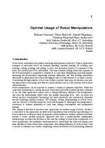
a) Single stage
b) A multistage BRAID
Figure 1. Representation of a dielectric polymer actuated BRAID
2
BACKGROUND AND LITERATURE
The operating principle of a dielectric polymer actuator is simple and shown in Figure 2. An elastomeric film is coated on both sides with compliant electrodes. As a voltage is applied across the electrodes, electrostatic forces will cause the film to compress in thickness and expand in area 8, 9. This area expansion can be used to actuate mechanical systems. The individual films can be layered to increase actuation forces.
Figure 2. Dielectric polymer actuator operating principle
Dielectric polymers have been proposed for use in linear actuators, loudspeakers, solid state optical devices, and as generators 5,10. A variety of geometric configurations convert the area expansion of the film to linear motion. For example, the actuator film can be constrained in planar frames or be rolled into tubes that change length 5. For these cases, the direction of the actuator motion is in the same plane as the film expansion. An example of an out-of-plane device is a cone-shaped actuator, in which the motion is normal to the undeformed film 11. Planar geometries of dielectric polymer actuators have been proposed to power a snake-like manipulator and an insectinspired hexapedal walker 5,12. A conical geometry has been proposed to power an inchworm robot 11. Since the actuators only work in tension, some external restoring force is required, which can be achieved in a variety of ways. For the case of the snake-like manipulator, each degree of freedom is controlled by an antagonistic pair of actuators. The hexapedal walker and the inchworm robot use return springs to provide the restoring force 11,12. For the actuator proposed here, the restoring force is provided by a flexible frame that is directly bonded to the film, resulting in a compact structural module with embedded actuation. A promising dielectric polymer is VHBTM 4910 made by 3MTM and sold as an adhesive tape. This is a very elastic material and has been shown to produce the greatest strains and energy densities in laboratory demonstrations. Up to 380% strain has been reported 5. However, such high strains have not been reported for actuators when the material is used in practical applications. This is due to the fact that in applications the boundary conditions that maximize performance are not maintained. The modular actuator concept presented in this paper is intended to eliminate this problem.
3
EMBEDDED ACTUATOR DESIGN
3.1 Operating principle The dielectric polymer that separates the electrodes experiences an electrostatic pressure as a charge is applied to the electrodes. If both the dielectric material and the electrodes are compliant, then the effective pressure is given by
V p = εε 0 E = εε 0 z
2
2
(1)
where ε is the relative dielectric constant, ε0 is the permittivity of free space, and E is the applied electric field, which is the ratio of the applied voltage (V) over the film thickness (z) 8,9,13. In general, the larger the effective pressure, the larger the actuator strain obtained. Understanding the implication of this equation is useful in actuator design. Equation 1 suggests that a high effective pressure will result from a large electric field. The maximum electric field that can be applied to the film without damaging it is the electric breakdown field. The breakdown field for VHBTM 4910 increases by more than an order of magnitude with pre-stretching 14. Since the electric field term (E) in Equation 1 is squared, pre-stretching this material can increase the maximum attainable effective pressure by two orders of magnitude. To fully exploit the potential of dielectric polymer actuators, the pre-stretching boundary conditions on the film are very important. The amount of prestretching of the film also affects the dielectric constant, however its variance with pre-strain is small and therefore believed to be less significant in actuator development 14. 3.2 Flexible Frames A simple way to produce linear motion with dielectric polymers is to stretch the actuator film between two parallel beams, as shown in Figure 3. As a voltage is applied to the electrodes, the film expands in area and allows the beams to separate if they are pre-loaded. Since the electric breakdown field increases with pre-stretching, such an implementation works best if the film is stretched in both planar directions. The pre-stretching also reduces the thickness of the film, which in turn reduces the voltage to achieve a given electric field. In this implementation, the vertical sides of the film are free, allowing the film to bow in. From Figure 3 it is evident that the amount of pre-stretching in the passive direction is not uniform throughout the actuator film. Since the film is largely incompressible (constant volume), it is thin close to the beams and thicker at the center. Applying an electric potential across the electrodes creates a non-uniform pressure and deformation of the film. Thus, not all areas of the film are actuated fully. Since the film is not constrained in the passive directions, it exhibits some motion in that direction upon actuation. This motion does not produce useful mechanical work. The challenge is to maintain the pre-stretched boundary conditions on the film without interfering with the desired motion of the actuator. One way to ensure uniformity in the film would be to increase the aspect ratio of the actuator by increasing the width (x) and reducing the height (y). However, such geometry and would be inappropriate for many applications. To solve this problem the film can be incorporated into a flexible frame, as shown in Figure 3b. The frame consists of two parallel beams that are connected with flexible links. The frame geometry is designed such that all areas of film undergo approximately equal expansion under actuation. The frame is a monolithic piece of Delrin®. Flexibility is provided by reducing the wall thickness in certain areas. The acrylic film is placed between two such frames.
a) Linear dielectric polymer actuator
b) Flexible frame
Figure 3. Methods of implementing dielectric polymer actuators
A second key function of the frame is that it provides an elastic restoring force that permits the actuator to work under both tension and compression. A welcome side-effect of the frame is that the risk of tearing of the film at its exposed edges is greatly reduced. The frame also prevents current arcs from developing around the edges of the film. Figure 4a shows an exploded view of the actuator module with the dielectric film integrated into its flexible frame. Higher actuation forces can be achieved by increasing the number of layers of film sandwiched between the frames. When using an even number of dielectric films, the electrodes can be arranged so that the two outer electrodes are both grounded. The high voltage is only present in the inside of the actuator and is thus shielded from the environment. The actuator discussed here uses two layers of the dielectric polymer as shown in Figure 4.
a) Exploded CAD representation
b) Photograph
Figure 4. Embedded flexible-frame actuator module
3.3 Actuator performance and physical actuator model To evaluate the performance of the actuator, the force-displacement characteristics were measured, see Figure 5. Curves are shown for an actuator at 0kV, 5.5kV, and completing a work cycle. The work cycle is generated by constraining the displacement of the actuator. A voltage of 5.5kV is applied and the force applied to the constraint is recorded. While keeping the voltage fixed, the constraint is moved until the actuator force is zero. The voltage is then removed and the process is repeated. The area enclosed by a counter-clockwise work cycle corresponds to the work output per cycle 6. actuator force-displacement 4 uncharged load line
3
2
force (N)
work cycle 1 charged load line
0
-1
-2
-3 13
14
15
16
17 18 length-y (mm)
19
20
Figure 5. Actuator stiffness and work cycle
21
22
The slope of the curve, which corresponds to the stiffness of the actuator, is nearly constant at 0.5N/mm for the range shown. Some hysteresis is evident, which is attributed to the viscoelastic losses of the film and frame 9. As shown in Figure 5, changing the voltage from 0 to 5.5kV offsets the curve, but does not significantly change its slope, suggesting that the stiffness of the actuator is independent of the state of actuation over the range shown. The actuator can therefore be modeled as a spring that changes its undeformed length upon actuation while maintaining its stiffness, as shown in Figure 6a. The corresponding force-displacement curves are shown in Figure 6b.
a) Actuator model
b) Work cycle
Figure 6. Idealized actuator model
In Figure 6b it can be seen that the vertical separation between the charged and uncharged stiffness curves represents the force differential the actuator can achieve if rigidly constrained. The horizontal separation of the curves at a given force corresponds to the actuator stroke, which is independent of external loading, provided the load remains constant throughout the stroke. Due to the compliance of the actuator, its length changes with external loading. The force generated by the actuator is not constant throughout the stroke. The force reaches its maximum at the beginning and linearly decreases to zero at the end of the stroke. However, for most applications including the BRAID, an actuator that provides uniform force is more desirable. Such actuator performance can be achieved by tuning the force displacement profiles in Figure 6b with a passive element. 3.4 Linear Bi-stable Elements Figure 7 shows a linear bi-stable element (LBE) and its corresponding force-displacement characteristics. The LBE consists of a base that elastically supports two opposing flexure arms. As a slightly oversized insert is placed between the arms, it pre-loads the base and causes the assembly to have two stable configurations. Between these bi-stable states, there is a region where the force-displacement curve is approximately linear and has a negative slope, as shown in Figure 7b. The slope is a function of the geometry and material of the LBE. By varying the width of the insert, the slope of the force-displacement curve in the near-linear region can be tuned precisely. The stiffness of the actuator and LBE in parallel is equivalent to the sum of the actuator stiffness and LBE stiffness. Thus, by designing a LBE with a slope of negative 0.5N/mm over its linear range, the combined actuator module can be tuned to have zero stiffness (constant force output) over an operating range.
LBE force-displacement 2 approximate linear range
1.5 1
force (N)
0.5 0 -0.5 -1 -1.5 -2 -2.5 12
14
a) photograph
16
18
20 22 length-y (mm)
24
26
28
b) force-displacement profile
Figure 7. Linear bi-stable element
Figure 8a shows the force displacement characteristics of the combined actuator module including the passive element. The work cycle measurements presented Figure 5 were repeated. Figure 8a shows a range over which the actuator force is approximately constant. Comparing the work cycles in Figure 5 and Figure 8, the advantages of the compensated actuator become evident. The stroke of the actuator is increased from about 4mm to 8mm. By using mechanical stops the actuator motion can be confined to the zero-stiffness range. Such an actuator has uniform force-displacement characteristics and reaches the same endpoints regardless of loading, provided it is within actuator capability. Thus such an actuator module provides robust binary operation. By using the actuator in a binary fashion, the hysteresis introduced by the viscoelastic properties of the elastomer is no longer a concern. Figure 8b shows the displacement and current of the actuator versus time. Most of the current is drawn as the actuator charges. Some leakage current is drawn once the actuated state is reached. If the dielectric polymer actuator behaved as a true capacitor, there would be no current drawn at steady state. The actuator is switched off by draining the charge through a resistor. Theoretically, this energy could be recovered by circuitry and returned to an energy storage device such as a battery. While the voltage required for actuation is very high (5.5kV), the current drawn is extremely low. The peak current for the given actuator is about 0.03mA, which corresponds to a maximum electrical input of 0.165W. compensated actuator work cycle
actuator displacement and current
2
length-y (mm)
25
1.5 range with nearly constant force
1
force (N)
0.5
20 15 10
0
5
10 time (s)
15
20
0
5
10 time (s)
15
20
0.04 current (mA)
-0.5 -1 -1.5 -2 12
0
14
16
18 length-y (mm)
a) work cycle
20
22
24
0.02 0 -0.02
b) displacement and current
Figure 8. Performance of compensated actuator module
Figure 9 shows the actuator in its two states. The actuation force is about 1.5N. The actuator stroke is about 8mm, with the polymer film undergoing a strain of about 57%. The mass of a complete actuator unit is approximately 6 grams.
Most of this mass is due to the frame and bi-stable element. For a double-layered actuator, the mass of the dielectric polymer and electrodes itself is less than 0.1 grams, only a fraction of what the actuator is capable of lifting.
Figure 9. Embedded flexible-frame actuator
The range of motion of the actuator could be further increased by developing passive elements that have the desired negative stiffness over a larger range. The stroke of the current prototype is limited by the range of the LBE, rather than by the film or frame.
4
BRAID PROTOTYPE
When the actuators are implemented into the BRAID, they behave as structural elements with embedded actuation. Three parallel actuators form a single stage. A combination of identical stages forms the BRAID. The design goal of the BRAID is to produce a virtually all-plastic, lightweight, binary manipulator. Figure 10 shows a photograph of a single BRAID stage before the dielectric polymer actuators are integrated. The kinematics of the mechanism requires a revolute joint at the bottom of the actuator and a spherical joint at the top. One rotational DOF is provided by a cross-flexural hinge machined from Delrin®. The hinge at the top of the frame approximates a spherical joint for small motions. It consists of thin compliant leaf that connects two pointed stiff elements.
Figure 10. BRAID-skeleton without actuators
Figure 11 shows a 2-stage BRAID prototype manipulating a mirror. It has 6 binary DOF, allowing 26=64 discrete states. Each degree of freedom is controlled by a simple switch. The total mass of the 2 stage BRAID prototype is about 65grams. The mass of the active actuator material itself, i.e. the dielectric film and electrodes, accounts for only 1% of the total mass. This suggests that most of the weight savings could be achieved by optimizing the structure rather than the actuators themselves.
Figure 11. Photograph of a two-stage BRAID prototype
The performance of the BRAID presented here is sufficient to manipulate a small camera.
5
CONCLUSIONS
Dielectric polymer artificial muscles have been introduced to the field of high-DOF binary robotics. The performance of these actuators shows promise of making high-DOF binary robotic systems practical. The current challenge with dielectric polymer actuators lies with effectively implementing them such that their full potential is exploited to perform mechanical work. Here, this challenge was addressed by embedding the polymer actuators into flexible frames which maintained the desired boundary conditions on the actuator film. By adding a passive element, a self-contained actuator module was formed that could work both under tension and compression and produced approximately uniform force throughout the stroke. The active actuator area achieves a relative strain of 57% and provides a force of 1.5N, while weighing 6 grams. The 2-stage BRAID prototype shows promise that these actuators are a feasible alternative to conventional technologies in the near future. The simplicity of the actuators allows for a BRAID design that is virtually all-plastic, inexpensive, lightweight, and easy to control. Research in this program is continuing to develop devices that fully exploit the dielectric polymer actuators in very high DOF practical binary systems.
6
ACKNOWLEDGEMENTS
The support of the NASA Institute for Advanced Concepts (NIAC) for this research is acknowledged. The authors would like to thank Peter Weiss and Ebraheem Fontaine for their help in actuator development and fabrication of prototypes.
7 1 2 3 4 5 6
REFERENCES
G. Chirikjian, “A Binary Paradigm for Robotic Manipulators,” Proc. of IEEE International Conference on Robotics and Automation, Vol. 4, pp. 3063-3069, 1994. D. Lees, G. Chirikjian, “A Combinatorial Approach to Trajectory Planning for Binary Manipulators,” Proc. of the IEEE International Conf. on Robotics and Automation, Minneapolis, MN, 1996. M. Lichter, V. Sujan, S. Dubowsky, “Computational Issues in the Planning and Kinematics of Binary Robots,” 2002 IEEE International Conference on Robotics and Automation, Washington D.C., 2002. M. Hafez, M. Lichter, S. Dubowsky, “Optimized Binary Modular Reconfigurable Robotic Devices,” 2002 IEEE International Conference on Robotics and Automation, Washington, D.C., May 11-15, 2002. R. Pelrine, P. Sommer-Larsen, R. Konrbluh, R. Heydt, G. Kofod, Q. Pei, P. Gravesen, “Applications of Dielectric Elastomer Actuators,” in Smart Structures and Materials 2001: Electroactive Polymer Actuators and Devices, Yoseph Bar-Cohen, Editor, Proceedings of SPIE Vol. 4329, March 2001. K. Maejer, M. Rosenthal, R. Full, “Muscle-like actuators? A comparison between three electroactive polymers,” Smart Structrues and Materials 2001: Electroactive Polymer Actuators and Deevices, Yoseph Bar-Cohen, Editor, Proceedings of SPIE Vol. 4329, pp. 7-15, March 2001.
7 8 9 10 11 12
13 14
V. Sujan, M. Lichter, S. Dubowsky, “Lightweight Hyper-redundant Binary Elements for Planetary Exploration Robots,” Proc. 2001 IEEE/ASME International Conference on Advanced Intelligent Mechatronics (AIM '01) 811, Como, Italy, July 2001. R. Kornbluh, R. Pelrine, J. Joseph, R. Heydt, Q Pei, S. Chiba, “High-field electrostriction of elastomeric polymer dielectics for actuation,” in Smart Structures and Materials 1999: Electroactive Polymer Actuators and Devices, Yoseph Bar-Cohen, Editor, Proceedings of SPIE Vol. 3669, pp. 149-161, 1999. R. Pelrine, R. Kornblu, Q. Pei, J. Joseph, “High Speed Electrically Actuated Elastomers with Strain Greater Than 100%,” Science, Vol. 287, pp. 836-839, 2000. R. Pelrine, R. Kornbluh, J. Eckerle, P. Jeuck, S. Oh, Q. Pei, S. Stanford, “Dielectric Elastomers: Generator Mode Fundamentals and Applications,” in Smart Structures and Materials 2001: Electroactive Polymer Actuators and Devices, Yoseph Bar-Cohen, Editor, Proceedings of SPIE Vol. 4329, pp.148-156, March 2001. S. Cho, S. Ryew, J. Jeon, H. Kim, J. Nam, H. Choi, and K. Tanie, "Electrostrictive Polymer Actuator Using Elastic Restoring Force," Proceedings of 1st Intelligent Microsystem Symposium, pp. 1963-1968, 2001. J. Eckerle, S. Stanford, J. Marlow, J. Marlow, R. Schmidt, S. Oh, T. Low, S. Shastri “A Biologically Inspired hexapedal Robot Using Field-Effect Electroactive Elastomer Artificial Muscles,” in Smart Structures and Materials 2001: Electroactive Polymer Actuators and Devices, Yoseph Bar-Cohen, Editor, Proceedings of SPIE Vol. 4329, March 2001. R. Pelrine, R. Konrbluh, J. Joseph, “Electrostriction of polymer dielectrics with compliant electrodes as a means of actuations,” Sensor and Actuators A: Physical 64, pp. 77-85. G. Kofod, R. Kornbluh, R. Pelrine, P. Sommer-Larsen, “Actuation response of polyacrylate dielectric elastomers,” in Smart Structures and Materials 2001: Electroactive Polymer Actuators and Devices, Yoseph Bar-Cohen, Editor, Proceedings of SPIE Vol. 4329, p141-147, March 2001.