Journal of Theoretical and Applied Information Technology 20th July 2014. Vol. 65 No.2 © 2005 - 2014 JATIT & LLS. All rights reserved.
ISSN: 1992-8645
www.jatit.org
E-ISSN: 1817-3195
HYPERSPECTRAL FACE CLASSIFICATION IN WAVELET DOMAIN USING KNN CLASSIFIER 1
P.V.V.Kishore, 2A.S.C.S.Sastry, 3T.Krishna Murthy, 4B.Gowthami, 5P.Anjana K.L.University, Dept of E.C.E, KL University, Vaddeswaram, Green Fields, GUNTUR, AP, INDIA
1, 2, 3, 4,5
E-mail:
[email protected],
[email protected],
[email protected], 4
[email protected],
[email protected]
ABSTRACT Hyperspectral face images present constructive information captured using a Hyperspectral camera compared to normal RGB camera capturing face images. Hyperspectral imaging is the collecting and processing of information from across the visible electromagnetic spectrum. Hyper spectral imaging deals with the imaging of narrow spectral bands over a continuous visible spectral range, and produces the spectra of all pixels in the scene. In this research face recognition experimentation is done in near infrared hyperspectral images. The recognition is accomplished on hyperspectral face database consisting of 47 test subjects created by Hong Kong Polytechnic University. The database images of hyperspectral faces were collected using a CCD camera equipped with a liquid crystal tunable filter to provide 33 bands over the near-infrared (0.7_m-1.0_m). Experiments were conducted to demonstrate that this simple algorithm can be used to recognize faces that changes in facial pose and expression over time. Keywords: Hyperspectral, Face Classification and Identification, Wavelet based Fusion, Principle Component analysis (PCA), Minimum Distance Classifier(KNN). 1.
INTRODUCTION
Most commercially available cameras capture three spectral components (Red, Blue and Green) in the entire visible range to match human visual trichromacy. Hyperspectral cameras are a new breed of vision sensor systems that utilize the entire band of visible spectrum for image capture. Hyperspectral images supply an intense spectral variety to each pixel that has demonstrated their usefulness in many domains such as remote sensing [1]-[5], medical image diagnosis [6, 7], biometrics [8], and can simplify the analysis of everyday scenes [9] as well. Face recognition systems currently use geometric facial features in spatial domain [10, 11]. Several of these face recognition methods perform well on face databases captured under laboratory conditions [12]-[13]. The recognition takes a setback when there are significant changes in lighting on the face, face orientation [14]. In [14] the experimental results show a notable collapse in recognition performance when the front angle faces are rotated by around 30 degrees. For making the face recognition rotation invariant the research community has shifted towards 3D modeling which solves the orientation of frontal faces by 60 degrees[15].
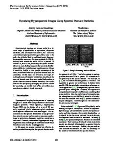
Partial face occlusion [16] also often brings poor performance. A method in [17] that divides the face into isolated face regions and good recognition rates are produced upto 16% occlusions on faces. A 3D face model has been proposed for face recognition across diverse face angles [18]-[19].These approaches has provided improved performance on small data set compared to 2D face recognition datasets that span into thousands of face images. Moreover the systems for 3D face recognition are computationally exhaustive and require substantial processing time. Thermal infrared imaging gives an unconventional imaging modality that has been used for face recognition [20]-[21] in the recent times. The techniques applied on thermal face images use spatial features and pose changes are difficult to recognize. The above discussed short comings of face recognition algorithms are approached in a complete different way by the use of spectral information [22]. Human skin radiates different spectral components when excited in the electromagnetic spectrum due to various pigments present in the human skin. These pigments induce significant transformations in the skin’s spectral reflectance [22]. Figure 1 shows the spectral inconsistency in human skin using measurements acquired at
366
Journal of Theoretical and Applied Information Technology 20th July 2014. Vol. 65 No.2 © 2005 - 2014 JATIT & LLS. All rights reserved.
ISSN: 1992-8645
www.jatit.org
computer vision laboratory, Department of Electrical Engineering and Computer Science, University of California. The figure 1 reproduced from [22].
The rest of the paper is organized as follows. Section 2 explains the experimental setup and hyperspectral face images capture. Processing large hyperspectral face databases for data reduction and information extraction is achieved in section 3. Section 4 discusses creation of feature vectors using principle components. Classification and Identification of hyper faces is simulated using minimum distance classifier is enlightened in section 5. Section 6 concludes the experimental research work with discussions. 2.
Figure 1: Reflectance Spectra Of Human Skin Of Four Test Subjects
In [22] the reflectance spectra measured from right side of their faces in the figure 1 were over the near infrared spectral range of 700nm-1000nm. The facial skin reflectance spectra have little changes in amplitude and phase for a single human face. It is also shown that pose changes does not affect the reflected spectral components from human faces. Figure 2 shows the set up established at computer vision laboratory, Department of Electrical Engineering and Computer Science, University of California for capturing hyperspectral face images. In this paper the authors acquired the database from this computer vision laboratory by requesting the researchers at university of California.
E-ISSN: 1817-3195
HYPERSPECTAL FACE IMAGES
For this research from the database of hyperspectral face images a set of 45 images are considered for experimentation. The database is acquired from hyperspectral face data base developed by The Biometric Research Centre (UGC/CRC) at The Hong Kong Polytechnic University Hyperspectral Face Database (PolyUHSFD)[23]. Each set of hyperspectral face image has three sets of face images per subject in left, center and right directions. The database is created with 25 human faces with 8 female and 17 male faces. The spectral range is set as 400nm to 720nm with a step length of 10nm with a total of 33 bands. A total of 33 spectral components are present in a single hyperspectral cube. Figure 3 shows a sample of 33 spectral faces for a female human subject captured using a hyperspectral camera at PolyUHSFD.
Figure 3: 33 Hyperspectral Faces Of A Female Subject At Polyu-HSFD
The database also consists of 3D face hyper cubes of resolution 220×180×33 for each face. Each hyper face is having three orientations left, center and right as shown in figure 4. For each face captured using hyperspectral camera the data generated is enormous. This research has around three sets of hyper cubes for left, center and right faces of height 220, length 180 with 33 spectral components, i.e. 33 hyper faces as shown in figure 3. Figure 2 Setup For Capturing Hyperspectral Face Images At Computer Vision Laboratory [22]
367
Journal of Theoretical and Applied Information Technology 20th July 2014. Vol. 65 No.2 © 2005 - 2014 JATIT & LLS. All rights reserved.
ISSN: 1992-8645
www.jatit.org
E-ISSN: 1817-3195
having unique properties are transformed using time frequency scaling of wavelet transform individually. Each image transformation produces four coefficients at assumed level 1, known as approximate coefficients, horizontal coefficients, vertical coefficients and diagonal coefficients. Different fusion rules are applied on these transform coefficients such as max-min, max-max etc. For example in max-min rule, maximum of approximate coefficients and minimum of remaining detailed coefficients are preserved and 2D transformation model is created. Finally by applying 2D inverse transformation in wavelet domain fabricates into an enhanced fused image. Different fusion techniques using wavelets are discussed with respect to ultrasound images and CV segmented images. Eight fusion rules are applied for Denoising and enhancing edges of medical ultrasound images.
Figure 4: Hyperspectral Database Faces In Different Orientations
The primary task in any hyperspectral domain is to transform the huge hyper image cubes into a plane where the same information is represented with reduced number of samples. In this paper we used Discrete Wavelet Based Image Fusion algorithm to fuse the hyperspectral cube of 33 spectral components into 16, 8, 4, 2 and finally one face image per subject. 3. DISCRETE WAVELET FUSION The hyper face for a single subject spans 33 spectral images of size 220×180. Operations on such large data on computers require a huge computing power. To optimize the computing power to a certain extent, it is proposed in this research to minimize the huge data sets. This task of reducing hyper data for each face is given to discrete wavelet transform based fusion techniques [24-27]. Hence an attempt is made in this research paper to preserve the spectral quality of hyperspectral images after image fusion is performed. The fusion of hyperspectral images in accomplished using 2D discrete wavelet transform based fusion rules. In literature quite a number [28]-[30] of fusion rules are proposed by researchers. From that we attempted four rules for our experimentation. Image fusion processes intermingle two diverse sets of images by extracting information that is distinctive to a particular image, there by fabricating an improved image. Wavelet based medical image fusion has gained popularity in the recent past. In wavelet based fusion two images
1) Max-Max Max-Max fusion rule using wavelet transform computes the maximum values of both approximate coefficients H
A
Whf ψ and V
detailed
coefficients
D
Whf ψ , Whf ψ and Whf ψ of hyperspectral face images in spectral range 400nm-560nm and hyperspectral face images in spectral range 570nm720nm. Retain the maximum values at that particular location and discard the minimum values for each coefficient. The max-max fusion rule is formulated as
368
WψF
max(W ψ A , W ψ A ) hf hf H max(W ψ , W ψ H ) hf hf = V V max(Whf ψ , Whf ψ ) D D max(W ψ ,W ψ ) M S
(1)
Max-Max fusion rule is illustrated in figure 5.
Figure 5: Max-Max Fusion Rule In Wavelet Domain
Journal of Theoretical and Applied Information Technology 20th July 2014. Vol. 65 No.2 © 2005 - 2014 JATIT & LLS. All rights reserved.
ISSN: 1992-8645
www.jatit.org
2) Max-Min The max-min fusion rule is formulated using 2D discrete wavelet transform and max-min fusion rule is implemented as shown in the figure 6.
E-ISSN: 1817-3195
Mean-Mean fusion rule is computed using the expression
W ψF
W ψ A hf W ψ H hf = V W h f ψ D W h f ψ
+ W hf ψ
A
+ W hf ψ
H
+ W hf
ψ
+ W hf
ψ
V
D
2 2
(3)
2 2
4) Min-Max The min-max fusion rule says select the minimum values from approximate coefficients and maximum values from detailed coefficients. Mathematically Figure 6: Max-Min Fusion Rule
The max-min fusion rule says select the maximum values from approximate coefficients and minimum values from detailed coefficients. Mathematically
WψF
WψF
max(W ψ A , W ψ A ) -Approximate Coff's hf hf ψH ψH min(Whf , Whf ) (2) = ψV ψV min(Whf , Whf ) -Detailed Coff's D D min(Whf ψ ,Whf ψ )
min(W ψ A , W ψ A ) -Approximate Coff's hf hf H ψH max( W , W hf ψ ) hf = ψV ψV max(W hf , W hf ) -Detailed Coff's D D max(W hf ψ , Whf ψ )
(4)
Figure 8 shows the fusion rule pictorially.
3) Mean-Mean Mean-Mean fusion rule evaluates the average value at each position of approximate and detailed coefficients for hyperspectral faces images of 400nm-560nm and 570nm-720nm respectively. Mean-Mean wavelet based fusion rule is shown in figure 7.
Figure8: Min-Max Fusion Rule
5) Min-Min Minimum coefficient values computed for respective approximated and detailed coefficients of original ultrasound and segmented image form the basis for min-min rule. Min-Min rule is articulated mathematically as
Figure7: Mean-Mean Fusion Rule
min(W ψ A , W ψ A ) M S min(W ψ H , W ψ H ) M S (5) WψF = V ψV min(WM , WSψ ) D D min(WM ψ , WSψ ) Figure 9 explicates min-min fusion rule using multiresolution wavelet transform.
369
Journal of Theoretical and Applied Information Technology 20th July 2014. Vol. 65 No.2 © 2005 - 2014 JATIT & LLS. All rights reserved.
ISSN: 1992-8645
www.jatit.org
E-ISSN: 1817-3195
Also known as karhunen Loeve (KL) transform which uses factorization to transform data according to its statistical properties. This data transformation is particularly useful for classification problems when data set is very large. PCA reduces the dimensions of highly correlated input vectors.
Figure 9: Min-Max Fusion Rule The result of fusion rules on center 33 hyperspectral face images of figure 3 is shown in figure 10.
The hyperspectral fused image matrix for a single face is 220×180 and we have 3 faces per subject in left, center and right orientations. To reduce the dimensionality of the feature matrix that uniquely models fused images in three orientations, PCA is applied. PCA extracts the principle components from these three fused images uniquely by using the concept of matrix factorization. Always start with normalizing the input vectors so they have zero mean and unity variance. The mathematics of PCA can be summarized in the following steps. The feature matrix consists of spectral numbers from fused hyper faces in three directions. Each feature representing a face is a 3 Dimension matrix of size 3×180. Each row in the matrix corresponds to face orientation and the values in each row uniquely model the spectral components in a hyper face of a single subject. Figure 11 shows feature vector matrix and Figure 12 shows their uniqueness. Three rows in the feature vector matrix correspond to a hyper face for left, centre and right orientations of a single subject which inputs the classifier in the next stage.
Figure 10: Images Showing Final Fused Image From A Set Of 33 Hyperspectral Images Using Fusion Rules
Observations on figure 10 reveal that the visual quality of max-max fusion and mean-mean fusion produce is exceptionally better compared to other fusion rules used in this paper. Feature vector is extracted from max-max fused image using principle component analysis (PCA).
Figure 11: Feature Matrix
4. PCA BASED FEATURE VECTOR The single image obtained from previous stage using fusion rule max-max is treated with principal component analysis (PCA) [79]. This operation generates a feature vector that uniquely models that particular fused hyper spectral center face. This feature vector is used to create database of faces. In this research PCA is used to compare the results with RGB face image classification using PCA with Hyperspectral face image classification using PCA. PCA in this case is used only to extract and construct a feature vector.
370
Figure 12: Graph Showing Uniqueness Of Feature Vectors For 5 Hyper Faces
Journal of Theoretical and Applied Information Technology 20th July 2014. Vol. 65 No.2 © 2005 - 2014 JATIT & LLS. All rights reserved.
ISSN: 1992-8645
5.
www.jatit.org
KNN CLASSIFIER
The knn classifier is a method for classifying faces based on closest training paradigms in the feature space created from PCA on fused hyper images. K-Nearest Neighbors (KNN) classification the data is divided into a test set and a training set. The training data is the feature matrix generated from PCA treated fused hyper faces. Test data sample is a row vector generated from the any of the spectral components of hyper faces. To create a test vector we have 33 spectral faces in a particular orientation per subject. In all three orientations we have 33×3 test vectors per human face. K-Nearest neighbors are found for each row in the test vector. K-nearest neighbors are computed using a distance metric such as Euclidean distance using the formulation
d eu ( f train , f test ) =
k
∑( f
i
train
E-ISSN: 1817-3195
orientations. Each face is captured using a hyperspectral camera which has a capture of 400nm to 720nm. Hence each face is having a 99 spectral faces in the spectral range 400nm to 700nm. Figure 13, 14 and 15 give a glimpse of the database used.
− fitest ) (6)
i =1
Figure 13: Hyperspectral Test Faces In Left Orientation
d eu ( f train , f test ) is the Euclidean distance between fi train the training set and fitest the test set. The classification is found by the minimum distance between test samples and training samples at random. If the distance is zero for all kth neighbors, the all the candidates in the test set are a part of the training data. Once distances are measured, classification of test data into class is performed using Liner Discriminate analysis (LDA). LDA assigns higher weight to a class near to the training data set. The weight vector is formulated as k
w(ci ) =
∑ j =1, c j = ci
1 eu
d (fj
train
, f test )
(7) Figure 14: Hyperspectral Test Faces In Front Orientation
Once class is divided, identification of the test subject is performed using the above equation. 6.
RESULTS AND DISCUSSION
The proposed face classification process involves the use of hyperspectral faces instead of traditional RGB faces. The data set of hyperspectral face images is used from hyperspectral face data base developed by The Biometric Research Centre (UGC/CRC) at The Hong Kong Polytechnic University Hyperspectral Face Database (PolyUHSFD)[23]. A set of 47 human face subjects are used in the hyperspectral face database. Each of the 47 faces are having a left, right and center
This huge data makes the computer processing of recognition task slower. Therefore to data size is reduced using wavelet based fusion methods. Four different wavelets were used at four levels with five fusion rules for this experimentation. ‘Haar’, ‘db2’, ‘sym3’ and ‘bior3.3’ were applied at 4 levels to convert 33 spectral faces per subject per orientation into 1 hyper fused face. The one hyper fused face is a combination all spectral components. Fusion rules such as MAX-MAX, MAX-MIN, MEAN-MEAN, MIN-MAX and MIN-MIN are applied.
371
Journal of Theoretical and Applied Information Technology 20th July 2014. Vol. 65 No.2 © 2005 - 2014 JATIT & LLS. All rights reserved.
ISSN: 1992-8645
www.jatit.org
E-ISSN: 1817-3195
Figure 17: Fusion With MAX-MAX At 4 Different Levels Of ‘Db2’ Wavelet Decomposition
Figure 15: Hyperspectral Test Faces in Right Orientation
Fusion of 2 hyperspectral images of wavelengths 510nm and 540nm is demonstrated in figure 16 using ‘db2’ mother wavelet at level-2 using MAX-MAX fusion rule.
Fusion produces a single hyper image which is consisting of most of the spectral components of all 33 spectral image faces per orientation. For each orientation i.e. left, front and right we have after fusion 3 faces per subject of size 220×180. Feature vector is created by applying principle component analysis (PCA). The 220×180 face matrix is converted by PCA and only first 180 principle components are preserved i.e. one per column is obtained. For 3 facial orientations we have a 3×180 sample feature matrix per subject. This 3×180 matrix is reshaped to form 1×540 row feature vector per subject face in all three orientations. For all the 47 test subjects in three different orientations we have a feature training matrix that defines face database is of size 47×540. This training matrix is used as database of hyper faces. The sample are in this database are unique to a particular subject as shown by the graph figure 12. Minimum distance classifier with Euclidian distance is used to classify hyper faces. For testing we have used the faces with slightly modified orientations as shown in figure 18.
Figure 16: MAX-MAX Fusion Rule for ‘db2’ wavelet at level-2 using MATLAB fusion GUI
Fusion with ‘db2’ wavelet for the above discussed hyper faces is performed at 4 different levels of decomposition. Figure 17 reveals the quantitative facts about visual quality of fused images at 4 different levels of decomposition. From figure 17 we observe that as the level increases there is a slight change in spectral composition of the hyper images.
372
Figure 18: Test Faces Used For Testing The Classifier
Journal of Theoretical and Applied Information Technology 20th July 2014. Vol. 65 No.2 © 2005 - 2014 JATIT & LLS. All rights reserved.
ISSN: 1992-8645
www.jatit.org
Classifier is tested using hyperspectral faces in the 400nm to 720nm wavelength with orientations different from those available in the training set. The true classification rate of the classifier is computed using the formula CRtrue =
Number of Correct Face Classifications ×100 (8) Tota l Number of Faces For Classification
False classification rate can also be computed to understanding the failure rate of the classifier. Center faces of two test subjects against the two sets of training vectors is applied to the classifier and the results are plotted in the figure 19. The training set is bifurcated into two groups. Group 1 with 2 subjects containing left, front and right samples and Group 2 with another 2 subjects.
E-ISSN: 1817-3195
Test samples from are chosen from original hyper faces of two subjects one in each group. From figure 19 it can be observed that each sample face is classified with maximum number of samples from training matching the test faces sample. From figure 19 we can see that the test data in group 1 i.e. red circles overlaps on to training group 1 samples i.e. red plus signs at most of the locations in the plot. Similar results are obtained by choosing test samples consisting of right and left faces. The classifier output is presented in figure 20. The true classification rates CR true for the above two cases are 97.34% and 96.87% respectively. The false classification for hyper face recognition is very minute with values of 2.66% for front faces and 3.13% for left and right faces.
Figure 19: Classification Results Of Front Faces With Two Test Samples And Two Setes Of Training Data
Figure 20: Classification Results Of Left And Right Faces With Two Test Samples And Two Setes Of Training Data
373
Journal of Theoretical and Applied Information Technology 20th July 2014. Vol. 65 No.2 © 2005 - 2014 JATIT & LLS. All rights reserved.
ISSN: 1992-8645
www.jatit.org
The average true classification rate with the entire test sample faces stands at 98.77%. The test samples are completely different face images with different orientations and spectral components. The results when compared to similar algorithms with RGB faces with different orientation produced very small true classification rates. This was discussed in[14]. 7.
CONCLUSION
This paper presents a old and standard techniques of face classification on a completely different set of face images called Hyperspectral Images. Hyperspectral faces form data cubes of large sizes which are successfully treated with wavelet fusion resulting in reduced hyper data. Fusion technique is chosen in such a way as to preserve maximum hyper data from 33 spectral components. Further feature vector is constructed by treating these fused hyper faces with PCA. PCA helps in identifying most distinct spectral components. Faces in various orientations are tested and classified using minimum distance classifier. The response of the classifier was a staggering 98% for most of the test faces against the fused faces. Finally, hyperspectral face recognition is the technology of the future where simple computational techniques produce excellent classification rates for different orientations. REFRENCES: [1]
[2]
[3]
[4]
[5]
Melgani, Farid, and Lorenzo Bruzzone. "Classification of hyperspectral remote sensing images with support vector machines." Geoscience and Remote Sensing, IEEE Transactions on 42.8 (2004): 1778-1790. Chang, Chein-I., ed. Hyperspectral imaging: techniques for spectral detection and classification. Vol. 1. Springer, 2003. Thenkabail, Prasad S., Ronald B. Smith, and Eddy De Pauw. "Hyperspectral vegetation indices and their relationships with agricultural crop characteristics." Remote sensing of Environment 71.2 (2000): 158-182. Lee, Zhongping, et al. "Hyperspectral remote sensing for shallow waters. 2. Deriving bottom depths and water properties by optimization." Applied Optics 38.18 (1999): 3831-3843. Blackburn, George Alan. "Quantifying chlorophylls and caroteniods at leaf and canopy scales: An evaluation of some hyperspectral approaches." Remote sensing of environment 66.3 (1998): 273-285.
E-ISSN: 1817-3195
[6] D. Dicker, J. Lerner, P. Van Belle, S. Barth, D. Guerry, et al.Differentiation of normal skin and melanoma using high resolutionhyperspectral imaging. Cancer biology & therapy,5(8):1033, 2006. [7] Stamatas, Georgios N., et al. "Non‐Invasive Measurements of Skin Pigmentation In Situ." Pigment Cell Research 17.6 (2004): 618-626. [8] Boyce, Christopher, et al. "Multispectral iris analysis: A preliminary study51." Computer Vision and Pattern Recognition Workshop, 2006. CVPRW'06. Conference on. IEEE, 2006. [9] Chakrabarti, Ayan, and Todd Zickler. "Statistics of real-world hyperspectral images." Computer Vision and Pattern Recognition (CVPR), 2011 IEEE Conference on. IEEE, 2011. [10] Ahonen, Timo, Abdenour Hadid, and Matti Pietikainen. "Face description with local binary patterns: Application to face recognition." Pattern Analysis and Machine Intelligence, IEEE Transactions on 28.12 (2006): 2037-2041. [11] Li, Zhifeng, Dahua Lin, and Xiaoou Tang. "Nonparametric discriminant analysis for face recognition." Pattern Analysis and Machine Intelligence, IEEE Transactions on 31.4 (2009): 755-761. [12] Kong, Seong G., et al. "Recent advances in visual and infrared face recognition—a review." Computer Vision and Image Understanding 97.1 (2005): 103-135. [13] Etemad, Kamran, and Rama Chellappa. "Discriminant analysis for recognition of human face images." JOSA A 14.8 (1997): 1724-1733. [14] R. Gross, J. Shi, and J. Cohn, “Quo Vadis Face Recognition?”Technical Report CMU-RI-TR01-17, Robotics Inst., Carnegie-Mellon Univ., June 2001. [15] R. Gross, I. Matthews, and S. Baker, “Appearance-Based Face Recognition and Light-Fields,” Technical Report CMU-RI-TR02-20, Robotics Inst., Carnegie-Mellon Univ., Aug. 2002. [16] Wright, John, Allen Y. Yang, Arvind Ganesh, Shankar S. Sastry, and Yi Ma. "Robust face recognition via sparse representation." Pattern Analysis and Machine Intelligence, IEEE Transactions on 31, no. 2 (2009): 210-227. [17] Hotta, Kazuhiro. "Robust face recognition under partial occlusion based on support vector machine with local Gaussian summation kernel." Image and Vision Computing 26.11 (2008): 1490-1498.
374
Journal of Theoretical and Applied Information Technology 20th July 2014. Vol. 65 No.2 © 2005 - 2014 JATIT & LLS. All rights reserved.
ISSN: 1992-8645
www.jatit.org
[18] Kakadiaris, Ioannis A., Georgios Passalis, George Toderici, Mohammed N. Murtuza, and Theoharis Theoharis. "3D Face Recognition." In BMVC, pp. 869-878. 2006. [19] Bronstein, Alexander M., Michael M. Bronstein, and Ron Kimmel. "Expressioninvariant 3D face recognition." In Audio-and Video-Based Biometric Person Authentication, pp. 62-70. Springer Berlin Heidelberg, 2003. [20] Socolinsky, Diego A., Andrea Selinger, and Joshua D. Neuheisel. "Face recognition with visible and thermal infrared imagery." Computer Vision and Image Understanding 91, no. 1 (2003): 72-114. [21] Kong, Seong G., Jingu Heo, Besma R. Abidi, Joonki Paik, and Mongi A. Abidi. "Recent advances in visual and infrared face recognition—a review." Computer Vision and Image Understanding Vol(97), no. 1 (2005): 103-135. [22] Zhihong Pan, Glenn Healey, Manish Prasad, and Bruce Tromberg. “Face Recognition in Hyperspectral Images.” Ieee Transactions On Pattern Analysis And Machine Intelligence, Vol. 25, No. 12, December 2003,1552-1560. [23] Wei Di, Lei Zhang, David Zhang, and Quan Pan,“Studies on Hyperspectral Face Recognition in Visible Spectrum With Feature Band Selection” Ieee Transactions On Systems, Man, And Cybernetics—Part A: Systems And Humans, Vol. 40, No. 6, November 2010,1354-1361. [24] Kishore, P. V. V., & Rajesh Kumar, P. (2012). A Video Based Indian Sign Language Recognition System (INSLR) Using Wavelet Transform and Fuzzy Logic. International Journal of Engineering & Technology (09754024), 4(5). [25] Kishore, P. V. V., & Kumar, P. R. (2012). A Model For Real Time Sign Language recognition System. International Journal of Advanced Research in Computer Science and Software Engineering, vol.2,(6). [26] Kishore, P. V. V., Kumar, P. R., Kumar, E. K., & Kishore, S. R. C. (2011). Video Audio Interface for Recognizing Gestures of Indian Sign. International Journal of Image Processing (IJIP), 5(4), 479. [27] N.Venkatram, L.S.S.Reddy, P.V.V.Kishore, Multiresolution Medical Image Watermarking for Telemedicine Applications, CiiT International Journal of Digital Image Processing, Vol(6),Issue 1, Jan 2014,pp6-15.
E-ISSN: 1817-3195
[28] S. Frechette, V.K. Ingle, (2005),Gradient based multi focus video image fusion, IEEE Conference on Advanced Video and Signal Based Surveillance, pp. 486–492. [29] F. Sadjadi,( 2005), Comparative image fusion analysis, Joint IEEE International Workshop on OTCBVS, pp. 8–15. [30] Yufeng Zheng, Edward A. Essock, Bruce C. Hansen, Andrew M. Haun, “A new metric based on extended spatial frequency and its application to DWT based fusion algorithms,” International Journal of Information Fusion, vol. 8,no.2,pp.177-192, April, 2007. [31] C. Twining, C. Taylor, The use of kernel principal component analysis to model data distributions, Pattern Recognition, 2003,36 (1): 217–227. [32]M Kirby, L Sirovech, Application of the KL procedure for the characterization of human Faces. IEEE Trans. On Pattern Analysis and Machine Intelligence, 1990, 12(1): 103-108.
375