HYSEP is a computer program that can be used to separate a streamflow ...... 101-110. Sloto, R.A., Cecil, L.D., and Senior, L.A., 1991, Hydrogeology and ...
HYSEP: A COMPUTER PROGRAM FOR STREAMFLOW HYDROGRAPH SEPARATION AND ANALYSIS U.S. GEOLOGICAL SURVEY Water-Resources Investigations Report 96-4040
HYSEP: A COMPUTER PROGRAM FOR STREAMFLOW HYDROGRAPH SEPARATION AND ANALYSIS by Ronald A. Sloto and Michèle Y. Crouse
U.S. GEOLOGICAL SURVEY Water-Resources Investigations Report 96-4040
Lemoyne, Pennsylvania 1996
U.S. DEPARTMENT OF THE INTERIOR BRUCE BABBITT, Secretary
U.S. GEOLOGICAL SURVEY Gordon P. Eaton, Director
The use of firm, trade, and brand names in this report is for identification purposes only and does not constitute endorsement by the U.S. Geological Survey.
For additional information write to:
Copies of this report may be purchased from:
District Chief U.S. Geological Survey 840 Market Street Lemoyne, Pennsylvania 17043-1586
U.S. Geological Survey Branch of Information Services Box 25286 Denver, Colorado 80225-0286
ii
CONTENTS Page Abstract . . . . . . . . . . . . . . . . . . . . . . . . . . . . . . . . . . . . . . . . . . . . . . . . . . . . . . . . . . . . . . Introduction . . . . . . . . . . . . . . . . . . . . . . . . . . . . . . . . . . . . . . . . . . . . . . . . . . . . . . . . . . . Purpose and scope . . . . . . . . . . . . . . . . . . . . . . . . . . . . . . . . . . . . . . . . . . . . . . . . . . . Limitations and cautions . . . . . . . . . . . . . . . . . . . . . . . . . . . . . . . . . . . . . . . . . . . . . .
1 1 2 2
Hydrograph-separation methods . . . . . . . . . . . . . . . . . . . . . . . . . . . . . . . . . . . . . . . . . . . Fixed-interval method . . . . . . . . . . . . . . . . . . . . . . . . . . . . . . . . . . . . . . . . . . . . . . . . Sliding-interval method. . . . . . . . . . . . . . . . . . . . . . . . . . . . . . . . . . . . . . . . . . . . . . . Local-minimum method . . . . . . . . . . . . . . . . . . . . . . . . . . . . . . . . . . . . . . . . . . . . . .
3 5 6 7
Program input requirements . . . . . . . . . . . . . . . . . . . . . . . . . . . . . . . . . . . . . . . . . . . . . . 8 Program output . . . . . . . . . . . . . . . . . . . . . . . . . . . . . . . . . . . . . . . . . . . . . . . . . . . . . . . . 9 Hydrograph separation . . . . . . . . . . . . . . . . . . . . . . . . . . . . . . . . . . . . . . . . . . . . . . . 9 Cumulative annual base-flow distribution . . . . . . . . . . . . . . . . . . . . . . . . . . . . . . . . 9 Flow duration . . . . . . . . . . . . . . . . . . . . . . . . . . . . . . . . . . . . . . . . . . . . . . . . . . . . . 11 Seasonal flow distribution. . . . . . . . . . . . . . . . . . . . . . . . . . . . . . . . . . . . . . . . . . . . 12 Daily-values files . . . . . . . . . . . . . . . . . . . . . . . . . . . . . . . . . . . . . . . . . . . . . . . . . . 12 How HYSEP works . . . . . . . . . . . . . . . . . . . . . . . . . . . . . . . . . . . . . . . . . . . . . . . . . . . . User interface . . . . . . . . . . . . . . . . . . . . . . . . . . . . . . . . . . . . . . . . . . . . . . . . . . . . . Commands . . . . . . . . . . . . . . . . . . . . . . . . . . . . . . . . . . . . . . . . . . . . . . . . . . . . Data panel . . . . . . . . . . . . . . . . . . . . . . . . . . . . . . . . . . . . . . . . . . . . . . . . . . . . . Assistance panel . . . . . . . . . . . . . . . . . . . . . . . . . . . . . . . . . . . . . . . . . . . . . . . . Instruction panel . . . . . . . . . . . . . . . . . . . . . . . . . . . . . . . . . . . . . . . . . . . . . . . . Special files . . . . . . . . . . . . . . . . . . . . . . . . . . . . . . . . . . . . . . . . . . . . . . . . . . . System defaults—TERM.DAT . . . . . . . . . . . . . . . . . . . . . . . . . . . . . . . . . Session record—HYSEP.LOG . . . . . . . . . . . . . . . . . . . . . . . . . . . . . . . . . Error and warning messages—ERROR.FIL . . . . . . . . . . . . . . . . . . . . . . .
13 13 13 15 16 16 16 16 17 17
Program options . . . . . . . . . . . . . . . . . . . . . . . . . . . . . . . . . . . . . . . . . . . . . . . . . . . Default settings . . . . . . . . . . . . . . . . . . . . . . . . . . . . . . . . . . . . . . . . . . . . . . . . . Specifying input files . . . . . . . . . . . . . . . . . . . . . . . . . . . . . . . . . . . . . . . . . . . . Selecting WDM file data sets . . . . . . . . . . . . . . . . . . . . . . . . . . . . . . . . . . . . . . Add. . . . . . . . . . . . . . . . . . . . . . . . . . . . . . . . . . . . . . . . . . . . . . . . . . . . . . . Browse . . . . . . . . . . . . . . . . . . . . . . . . . . . . . . . . . . . . . . . . . . . . . . . . . . . . Find . . . . . . . . . . . . . . . . . . . . . . . . . . . . . . . . . . . . . . . . . . . . . . . . . . . . . . Selecting program output . . . . . . . . . . . . . . . . . . . . . . . . . . . . . . . . . . . . . . . . . Tables . . . . . . . . . . . . . . . . . . . . . . . . . . . . . . . . . . . . . . . . . . . . . . . . . . . . . Data files . . . . . . . . . . . . . . . . . . . . . . . . . . . . . . . . . . . . . . . . . . . . . . . . . . Graphs . . . . . . . . . . . . . . . . . . . . . . . . . . . . . . . . . . . . . . . . . . . . . . . . . . . . Modifying plot parameters. . . . . . . . . . . . . . . . . . . . . . . . . . . . . . . . . . . . . Selection of hydrograph-separation method. . . . . . . . . . . . . . . . . . . . . . . . . . . Execution of the base-flow separation . . . . . . . . . . . . . . . . . . . . . . . . . . . . . . .
17 18 20 20 20 21 23 24 24 25 25 27 28 28
Summary . . . . . . . . . . . . . . . . . . . . . . . . . . . . . . . . . . . . . . . . . . . . . . . . . . . . . . . . . . . . 30 References cited. . . . . . . . . . . . . . . . . . . . . . . . . . . . . . . . . . . . . . . . . . . . . . . . . . . . . . . 31
iii
CONTENTS—CONTINUED Page Appendix 1. Annual base-flow summary . . . . . . . . . . . . . . . . . . . . . . . . . . . . . . . . . . . Appendix 2. Monthly summary. . . . . . . . . . . . . . . . . . . . . . . . . . . . . . . . . . . . . . . . . . . Appendix 3. Cumulative-distribution table . . . . . . . . . . . . . . . . . . . . . . . . . . . . . . . . . . Appendix 4. Flow-duration table. . . . . . . . . . . . . . . . . . . . . . . . . . . . . . . . . . . . . . . . . . Appendix 5. Seasonal-distribution table . . . . . . . . . . . . . . . . . . . . . . . . . . . . . . . . . . . . Appendix 6. Special files. . . . . . . . . . . . . . . . . . . . . . . . . . . . . . . . . . . . . . . . . . . . . . . .
34 35 36 37 41 42
TERM.DAT . . . . . . . . . . . . . . . . . . . . . . . . . . . . . . . . . . . . . . . . . . . . . . . . . . . . . . 42 HYSEP.LOG. . . . . . . . . . . . . . . . . . . . . . . . . . . . . . . . . . . . . . . . . . . . . . . . . . . . . . 45
ILLUSTRATIONS Figures 1-7.Graphs showing:
8. 9. 10. 11. 12. 13. 14. 15. 16. 17. 18.
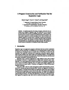
1. Daily mean streamflow and estimated base flow for French Creek near Phoenixville, Pa., 1992 . . . . . . . . . . . . . . . . . . . . 4 2. Hydrograph analysis using the fixed-interval method for French Creek near Phoenixville, Pa., April 1992. . . . . . . . . . . . . . . . 5 3. Hydrograph analysis using the sliding-interval method for French Creek near Phoenixville, Pa., April 1992. . . . . . . . . . . . . . . . 6 4. Hydrograph analysis using the local-minimum method for French Creek near Phoenixville, Pa., April 1992. . . . . . . . . . . . . . . . 7 5. Cumulative distribution function of mean annual streamflow, estimated mean annual surface runoff, and estimated mean annual base flow for French Creek near Phoenixville, Pa., 1969-92 . . . . . . . . . . . . . . . . . . . . . . . . . . . . . . . . 10 6. Duration of total streamflow, estimated surface runoff, and estimated base flow for French Creek near Phoenixville, Pa., 1969-92 . . . . . . . . . . . . . . . . . . . . . . . . . . . . . . . . 11 7. Estimated mean monthly surface runoff and base flow for French Creek near Phoenixville, Pa., 1969-92. . . . . . . . . . . . . . . . . 12 Basic screen layout and commands for HYSEP . . . . . . . . . . . . . . . . . . . . 14 Opening screen. . . . . . . . . . . . . . . . . . . . . . . . . . . . . . . . . . . . . . . . . . . . . . 18 Hierarchy of menus in HYSEP . . . . . . . . . . . . . . . . . . . . . . . . . . . . . . . . . 18 Processing steps following selection of the Execute option. . . . . . . . . . . . 19 Browse (WSB) data-set information selection screen . . . . . . . . . . . . . . . . 21 Browse (WSB) data-set information screens . . . . . . . . . . . . . . . . . . . . . . . 22 Output options screen. . . . . . . . . . . . . . . . . . . . . . . . . . . . . . . . . . . . . . . . . 24 Graphical output screen . . . . . . . . . . . . . . . . . . . . . . . . . . . . . . . . . . . . . . . 25 Plot modification menu . . . . . . . . . . . . . . . . . . . . . . . . . . . . . . . . . . . . . . . 26 Plot parameter modification menu . . . . . . . . . . . . . . . . . . . . . . . . . . . . . . . 27 Base name and date specification screen . . . . . . . . . . . . . . . . . . . . . . . . . . 29 iv
TABLES Page Table 1. U.S. Geological Survey National Water Data Storage and Retrieval System (WATSTORE) daily values 80-character record ASCII format . . . . . . . . . . . . . . . . . . . . . . . . . . . . . . . . . . . . . . . . . . 8 2. WDM file data search options . . . . . . . . . . . . . . . . . . . . . . . . . . . . . . . . . . . . 23 3. Output file name suffixes . . . . . . . . . . . . . . . . . . . . . . . . . . . . . . . . . . . . . . . . 29
APPENDIX 6 TABLES Table 1. TERM.DAT parameters . . . . . . . . . . . . . . . . . . . . . . . . . . . . . . . . . . . . . 34 2. MENCRA values and corresponding program response . . . . . . . . . . . . 35 3. Example TERM.DAT file . . . . . . . . . . . . . . . . . . . . . . . . . . . . . . . . . . . . 36 4. TERM.DAT parameters for color display (DOS-based computers) . . . . . . . . . . . . . . . . . . . . . . . . . . . . . . . . . . . 37 5. Codes used for nonprinting characters in a log file. . . . . . . . . . . . . . . . . 41 6. Description of example log file. . . . . . . . . . . . . . . . . . . . . . . . . . . . . . . . 42
CONVERSION FACTORS AND ABBREVIATIONS Multiply inch (in.)
By 25.4
To obtain millimeter
square mile (mi 2)
2.59
square kilometer
million gallons per day (Mgal/d)
0.04381
cubic meter per second
million gallons per day per square mile [(Mgal/d)/mi2]
0.0169
cubic meter per second per square kilometer
cubic foot per second (ft3/s)
0.02832
cubic meter per second
cubic foot per second per square mile [(ft3/s)/mi2]
0.01093
cubic meter per second per square kilometer
v
vi
HYSEP: A COMPUTER PROGRAM FOR STREAMFLOW HYDROGRAPH SEPARATION AND ANALYSIS By Ronald A. Sloto and Michèle Y. Crouse
ABSTRACT HYSEP is a computer program that can be used to separate a streamflow hydrograph into baseflow and surface-runoff components. The base-flow component has traditionally been associated with ground-water discharge and the surface-runoff component with precipitation that enters the stream as overland runoff. HYSEP includes three methods of hydrograph separation that are referred to in the literature as the fixed-interval, sliding-interval, and localminimum methods. The program also describes the frequency and duration of measured streamflow and computed base flow and surface runoff. Daily mean stream discharge is used as input to the program in either an American Standard Code for Information Interchange (ASCII) or binary format. Output from the program includes tables, graphs, and data files. Graphical output may be plotted on the computer screen or output to a printer, plotter, or metafile.
INTRODUCTION Hydrograph analysis is a useful technique in a variety of water-resource investigations. Separation of streamflow hydrographs into base-flow and surface-runoff components is used to estimate the ground-water contribution to streamflow. Hydrograph-separation techniques also have been used to quantify the ground-water component of hydrologic budgets and to aid in the estimation of recharge rates. In addition, base-flow characteristics determined by hydrograph separation of hydrographs from streams draining different geologic terranes have been used to show the effect of geology on base flow (Sloto and others, 1991, p. 29-33). White and Sloto (1990) analyzed streamflow hydrographs from 309 Pennsylvania streamflow-measurement stations to estimate base-flow-frequency characteristics. Hydrograph separation traditionally has been done manually. Two commonly used methods are base-flow-recession methods (Olmsted and Hely, 1962; Riggs, 1963; Rorabaugh, 1963) and curve-fitting methods (Pettyjohn and Henning, 1979; Linsley and others, 1982). Different hydrologists using the same manual hydrograph-separation method commonly produce different base-flow estimates. The use of a computer program removes inconsistencies inherent in manual methods and substantially reduces the time required for hydrograph separation. Separation of a streamflow hydrograph is based on a mathematical technique that mimics the way that humans have been separating hydrographs, rather than on the physics of the process. Thus, although HYSEP consistently applies various algorithms that are commonly used for hydrograph separation, hydrograph separation remains a subjective process. Computer hydrograph-separation methods were compared with published values determined manually for streams in southeastern Pennsylvania by Sloto (1991). Base flows estimated with computer methods agreed closely with those estimated by manual methods.
1
PURPOSE AND SCOPE This report documents the streamflow hydrograph-separation and analysis program referred to as HYSEP. HYSEP employs a character-based interface and can be used on multiple platforms. The program separates streamflow hydrographs into base-flow and surface-runoff components and performs frequency and duration analyses on both components. This report describes the HYSEP program, the hydrograph-separation and analysis methods used, program design and operation, input requirements, and program output. The methods for streamflow hydrograph separation used in this program were adapted from Pettyjohn and Henning (1979) and were originally incorporated in 1982 into a computer program that used streamflow data in standard U.S. Geological Survey (USGS) daily-values format. The version of the HYSEP program described by this report is coded so that other methods of hydrograph separation can easily be incorporated when the methods are computerized. Figures and appendixes in this report were produced by use of HYSEP.
LIMITATIONS AND CAUTIONS The streamflow hydrograph-separation methods used by this program are intended to provide estimates of base flow and surface runoff to streams. Generally, average annual estimates are more reliable than monthly or daily estimates of base flow or surface runoff. Base-flow estimates are affected by regulation, which changes the natural flow of a stream and influences both base flow and surface runoff. A flood-control reservoir, for example, slowly releases runoff after a storm, resulting in an apparent decrease in surface runoff and an apparent increase in base flow. Regulation includes reservoir storage and releases, discharge from quarry and mine dewatering, discharge from sewage treatment plants, and diversion for water supply. White and Sloto (1990, p. 22) found that the effect of regulation is site specific; annual base flows decreased for the majority of streams in the Delaware River Basin and increased for the majority of streams in the Susquehanna and Ohio River Basins subsequent to regulation. The accuracy of estimates of base-flow-frequency characteristics depends on the period of record used in the analysis. Record for a station operated during a period of extreme climatological conditions, such as mostly dry years, exhibits a bias toward the extreme. A longterm station with record representative of long-term climatological conditions provides a more reliable base-flow estimate because extremes have less weight in the determination of base-flow characteristics. Input data should be carefully checked. Plotting input data provides an excellent visual check for periods of suspect data. For large data sets, plotting the annual hydrograph to the screen for each year of data provides a quick and efficient check on the validity of the input data and the hydrograph separation. The use of this program to analyze data from multiple stations with long periods of record without carefully checking the input data may result in erroneous estimates of base flow and surface runoff. It is the responsibility of the user to correctly interpret the usefulness of any results for the specific application.
2
HYDROGRAPH-SEPARATION METHODS The HYSEP program uses three methods to separate the base-flow and surface-runoff components of a streamflow hydrograph—fixed interval, sliding interval, and local minimum. These methods can be described conceptually as three different algorithms to systematically draw connecting lines between the low points of the streamflow hydrograph. The sequence of these connecting lines defines the base-flow hydrograph. The techniques were developed by Pettyjohn and Henning (1979). Hydrograph separations for the streamflow-measurement station French Creek near Phoenixville, Pa., using the three methods are shown in figure 1. Each method is described below. The duration of surface runoff is calculated from the empirical relation: N=A0.2,
(1)
where N is the number of days after which surface runoff ceases, and A is the drainage area in square miles (Linsley and others, 1982, p. 210). The interval 2N* used for hydrograph separations is the odd integer between 3 and 11 nearest to 2N (Pettyjohn and Henning, 1979, p. 31). For example, the drainage area at the streamflow-measurement station French Creek near Phoenixville, Pa. (USGS station number 01472157), is 59.1 mi2. The interval 2N* is equal to 5, which is the nearest odd integer to 2N, where N is equal to 2.26. The hydrograph separation begins one interval (2N* days) prior to the start of the date selected for the start of the separation and ends one interval (2N* days) after the end of the selected date to improve accuracy at the beginning and end of the separation. If the selected beginning and (or) ending date coincides with the start and (or) end of the period of record, then the start of the separation coincides with the start of the period of record, and (or) the end of the separation coincides with the end of the period of record.
3
103 FIXED-INTERVAL METHOD
MEASURED FLOW ESTIMATED BASE FLOW
SLIDING-INTERVAL METHOD
MEASURED FLOW ESTIMATED BASE FLOW
LOCAL-MINIMUM METHOD
MEASURED FLOW ESTIMATED BASE FLOW
DISCHARGE, IN CUBIC FEET PER SEC ON D
102
10 103
102
10 103
102
10 JAN
FEB
MAR
APR
MAY
JUNE
JULY
AUG
SEPT
OCT
NOV
DEC
1992 Figure 1. Daily mean streamflow and estimated base flow for French Creek near Phoenixville, Pa., 1992.
4
FIXED-INTERVAL METHOD The fixed-interval method assigns the lowest discharge in each interval (2N*) to all days in that interval starting with the first day of the period of record (fig. 2). The method can be visualized as moving a bar 2N* days wide upward until the bar first intersects the hydrograph. The discharge at that point is assigned to all days in the interval. The bar is then moved 2N* days horizontally, and the process is repeated. The interval 2N* is 5 days in figure 2. For example, in the interval April 5 to 9, the lowest discharge, 49 ft3/s, is assigned as the base-flow component to every day in that interval. The assigned values are then connected to define the base-flow hydrograph.
100
DISCHARGE, IN CUBIC FEET PER SECOND
90 80 70
60
SURFACE RUNOFF
50
40 BASEFLOW
30 1 2 3 4 5 6 7 8 9 10 11 12 13 14 15 16 17 18 19 20 21 22 23 24 25 26 27 28 29 30 APRIL 1992
Figure 2. Hydrograph analysis using the fixed-interval method for French Creek near Phoenixville, Pa., April 1992.
5
SLIDING-INTERVAL METHOD The sliding-interval method finds the lowest discharge in one half the interval minus 1 day [0.5(2N*-1) days] before and after the day being considered and assigns it to that day (fig. 3). The method can be visualized as moving a bar 2N* wide upward until it intersects the hydrograph. The discharge at that point is assigned to the median day in the interval. The bar then slides over to the next day, and the process is repeated. In the interval April 16 to 20, the lowest discharge, 42 ft3/s, is assigned to April 18, the median day in the interval (fig. 3). The assigned daily values are then connected to define the base-flow hydrograph.
100
DISCHARGE, IN CUBIC FEET PER SECOND
90 80 70 SURFACE RUNOFF
60
50
40
BASEFLOW
30 1 2 3 4 5 6 7 8 9 10 11 12 13 14 15 16 17 18 19 20 21 22 23 24 25 26 27 28 29 30 APRIL 1992
Figure 3. Hydrograph analysis using the sliding-interval method for French Creek near Phoenixville, Pa., April 1992.
6
LOCAL-MINIMUM METHOD The local-minimum method checks each day to determine if it is the lowest discharge in one half the interval minus 1 day [0.5(2N*-1) days] before and after the day being considered. If it is, then it is a local minimum and is connected by straight lines to adjacent local minimums (fig. 4). The base-flow values for each day between local minimums are estimated by linear interpolations. The method can be visualized as connecting the lowest points on the hydrograph with straight lines. In figure 4, local minimums occur on April 9, 15, 21, and 24.
100
DISCHARGE, IN CUBIC FEET PER SECOND
90 80 70
60
SURFACE RUNOFF
50
BASEFLOW
40
30 1 2 3 4 5 6 7 8 9 10 11 12 13 14 15 16 17 18 19 20 21 22 23 24 25 26 27 28 29 30 APRIL 1992
Figure 4. Hydrograph analysis using the local minimum method for French Creek near Phoenixville, Pa., April 1992.
7
PROGRAM INPUT REQUIREMENTS The HYSEP program accepts daily mean stream discharge as input in either of two formats: (1) the standard USGS National Water Data Storage and Retrieval System (WATSTORE) daily values, 80-character record American Standard Code for Information Interchange (ASCII) format (table 1) (Williams, 1975, p. A21-A23); or (2) the binary, direct access Watershed Data Management (WDM) file format (Flynn and others, 1995, p. 12-14). Daily-values data in the WATSTORE format can be retrieved from the USGS WATSTORE or Automated Data Processing System (ADAPS) data bases. Data in the WATSTORE daily values format can be converted to the WDM format by the IOWDM program (Lumb and others, 1990, p. 163-211). Data for 1 station in the WATSTORE daily values format and up to 300 stations in the WDM format can be processed at one time. A minimum of 1 and a maximum of 100 years of data per station in either format can be processed.
Table 1. U.S. Geological Survey National Water Data Storage and Retrieval System (WATSTORE) daily values 80-character record ASCII format [Columns 1-24 are integers; columns 25-80 are decimal numbers] column
1
numeric code
Format number—Daily values are designated by the number 3.
2-16
Station-identification number.
17-20
Calendar year—A four-digit number representing the calendar year.
21-22
Month—A two digit number representing the month.
23-24
Record number—A two-digit number representing the days of the month for the data. The record number is coded as follows: Number 01 02 03 04
25-80
Days 1-8 9-16 17-24 25-31
Daily values—Eight, seven-column fields (25-31, 32-38, 39-45, 46-52, 53-59, 60-66, 67-73, 74-80) in which daily values are coded for the days designated. Blank fields are read as zero values.
8
PROGRAM OUTPUT Program output options, including tables, graphs, ASCII files, and WDM data sets, are described in the following sections. In the tables, missing values are designated by -1.0. Graphs may be plotted on the computer screen or sent to a printer, plotter, or metafile.
HYDROGRAPH SEPARATION The HYSEP program will produce an annual hydrograph of streamflow and estimated base flow for each year of record processed (fig. 1). The period of record analyzed can begin with any day of the calendar year. Tabular output from the hydrograph separation summarizes the quantity of estimated base flow and surface runoff and the percentage of streamflow as base flow and surface runoff. An annual summary of base flow in units of inches, cubic feet per second, and million gallons per day per square mile is provided by default (Appendix 1). Alternatively, a monthly summary can be selected that gives monthly values of mean streamflow (cubic feet per second), total streamflow (inches), mean base flow (cubic feet per second and million gallons per day per square mile), total base flow (inches), mean surface runoff (cubic feet per second), total surface runoff (inches), and percentage of streamflow as base flow (Appendix 2).
CUMULATIVE ANNUAL BASE-FLOW DISTRIBUTION A cumulative distribution function accumulates all of the probabilities of values less than or equal to the value of interest. When the probability density curve (probability distribution) is cumulated from the left, probabilities of not exceeding various magnitudes are obtained; this is commonly referred to as a frequency curve in hydrology (Riggs, 1968, p. 1-3). Cumulative distributions commonly are plotted on a probability scale, such that the theoretical curve is a straight line. Cumulative distribution functions of mean annual streamflow, estimated mean annual base flow, and estimated mean annual surface runoff for the period of record of a station can be tabled and plotted for any hydrograph-separation method. Mean annual base flows are arranged in order of magnitude beginning with the smallest as number one. A Weibull plotting position estimate of the probability (p) of an annual mean base-flow value being less than a particular magnitude is calculated by p = m/(n + 1),
(2)
where m is the order number of the individual year in the sample, and n is the number of years of record. The cumulative distribution function of mean annual streamflow, estimated mean annual base flow, and estimated mean annual surface runoff for 1969-92 for French Creek near Phoenixville, Pa., are shown in figure 5. Estimated mean annual base flow can be printed as a table (Appendix 3).
9
40
36
TOTAL STREAMFLOW SURFACE RUNOFF
32
BASE FLOW
RUNOFF, IN INCHES
28
24
20
16
12
8
4
0 0.5
2
5
10
20
50
70
90
95
98
99.5
PERCENTAGE OF TIME RUNOFF WAS LESS THAN OR EQUAL TO INDICATED VALUE
Figure 5. Cumulative distribution function of mean annual streamflow, estimated mean annual surface runoff, and estimated mean annual base flow for French Creek near Phoenixville, Pa., 1969-92.
For mean annual base flow, the recurrence interval is the average interval of time during which annual base flow will be less than a particular value. The recurrence interval is the inverse of the cumulative probability function. Recurrence interval (T) may be calculated by T = (n + 1)/m = 1/p,
(3)
where n is the number of years of record, and m is the order number of the individual year in the sample.
10
FLOW DURATION A flow-duration curve is the complement of a cumulative distribution function that shows the percentage of time specified mean daily discharges were equaled or exceeded during a given period (Searcy, 1959). The HYSEP program plots flow-duration curves for total streamflow, estimated base flow, and estimated surface runoff (fig. 6). A flow-duration table (Appendix 4) can be generated for total streamflow, estimated surface runoff, and estimated base flow.
103 TOTAL STREAMFLOW SURFACE RUNOFF
FLOW, IN CUBIC FEET PER SECOND
BASE FLOW
102
10 0.5
2
5
10
20
50
70
90
95
98
99.5
PERCENTAGE OF TIME FLOW WAS EQUALED OR EXCEEDED
Figure 6. Duration of total streamflow, estimated surface runoff, and estimated base flow for French Creek near Phoenixville, Pa., 1969-92.
11
SEASONAL FLOW DISTRIBUTION The HYSEP program will plot estimated mean monthly base flow and surface runoff as a bar graph (fig. 7). The graph shows seasonal differences in base flow and surface runoff. The estimated mean monthly base flow and surface runoff for French Creek at Phoenixville, Pa., for 1969-92 are shown in figure 7. The quantity of surface runoff exceeds that of base flow only in June. In addition, a seasonal-distribution table (Appendix 5) can be generated for estimated mean monthly base flow and surface runoff.
AVERAGE MONTHLY DISCHARGE, IN CUBIC FEET PER SQUARE MILE
2.5 BASE FLOW SURFACE RUNOFF
2
1.5
1
0.5
0 JAN
FEB MAR APR MAY JUNE JULY AUG SEPT OCT NOV DEC
Figure 7. Estimated mean monthly surface runoff and base flow for French Creek near Phoenixville, Pa., 1969-92.
DAILY-VALUES FILES Daily values of estimated base flow or surface runoff in the WATSTORE daily values format (table 1) can be written to a file by selecting the appropriate program option. The ASCII file that is generated can be used as input to other applications.
12
HOW HYSEP WORKS HYSEP was written to be portable and, therefore, can be used on multiple computer platforms. Installation procedures depend on the computer platform, and specific installation instructions are distributed with the software. Once the software is installed, type “hysep” to start the program.
USER INTERFACE Program interaction takes place in a screen 80 characters wide by 24 characters high. The basic screen layout is shown in figure 8. Each screen consists of a list of available commands displayed at the bottom and one or more boxed-in areas that are referred to as panels. Commands are used to obtain additional information and to move between screens. The three types of panels are data, assistance, and instruction. The data panel displayed at the top of the screen is always present. Data panels contain menus, forms, tables, and text to permit user interaction with the program. An assistance panel may be present depending on user or program assignments. When present, the assistance panel is displayed below the data panel (usually as the middle panel) and contains information, such as help messages, valid range of values, and details on program status. The instruction panel is displayed above the available commands when the user is expected to interact with the program. When present, the instruction panel contains information on what keystrokes are required to interact with the program. Each screen can be identified by a name and the path selected to reach the screen. The screen name appears in the upper left corner of the data panel, where the words “screen name” appear in figure 8. The first screen displayed by the program is named “Opening screen.” All subsequent screens are named on the basis of the menu option or program sequence that caused the current screen to be displayed. Screen names are followed by “(path)” (fig. 8), a string of characters consisting of the first letter(s) of the menu options selected in order to arrive at the current screen. In some cases, descriptive text may follow the path to further help identify the screen. The path can aid in keeping track of the position of the current screen in the menu hierarchy. For example, “Open (WFO)” indicates that the menu option Open was selected and that the path to this screen from the “Opening screen” consisted of three menu selections— Wdm, File, and Open.
COMMANDS The screen commands and their associated keystrokes are described in figure 8. A subset of the screen commands is available for any given screen. Most commands can be executed by pressing a single function key. (The designation for a function key is “F#” where # is the number of the function key.) All of the commands can be executed in “command mode.” Command mode is toggled on and off by pressing the semicolon (;) key1. In command mode, any command can be executed by pressing the first letter of the command name; for example, “o” or “O” for the Oops command. When commands are discussed in this report, the command name is spelled out with the function key or keystroke given in parentheses. For example, Accept (F2) is the most frequently used command. Use Help (F1) and Limits (F5) to obtain additional information about the current screen and Status (F7) to obtain information on the state of the program. Cmhlp (;c) will display information on the available commands. Use Quiet (F8) to close the assistance panel. To move
1 On
some systems the F3 key and (or) the escape key (Esc) may also work.
13
screen name (path)
HYSEP 2.0
Data panel
assistance type
Assistance panel instruction type
Instruction panel Help: F1 Accept: F2 Prev: F4 Limits: F5 Status: F7 Intrpt:F6 Quiet: F8 Cmhlp Oops
command
associated keystrokes1
description
Help
F1 or ;h
Accept
F2 or ;a F3c or ;c F3o or ;o F3d or ;d F3u or ;u F4 or ;p F5 or ;l
Displays help information in the assistance panel. The help information is updated as the user moves from field to field in the data panel or to a different screen. The program automatically closes the assistance panel if a screen is displayed for which no help information is available. Indicates that you have “accepted” the input values, menu option currently highlighted, or text message in the data panel. Selection of this command causes program execution to continue. Displays brief descriptions of the commands available on the screen.
Cmhlp Oops Dnpg Uppg Prev Limits
Intrpt Status Quiet Xpad
F6 or ;i F7 or ;s F8 or ;q F9 or ;x
Resets all data fields in an input form to their initial values. Displays next “page” of text in data panel. Available when all of the text cannot be displayed at one time. Redisplays previous “page” of text in data panel. Available after execution of Dnpg (F3d). Redisplays a previous screen. Any modifications in the data panel are ignored. Which screen is the previous one may be ambiguous in some cases. Displays valid ranges for numeric fields and valid responses for character fields. Information on field limits is updated as the user moves from field to field in the data panel or to a different screen by using the arrow keys or the Enter (Return) key. Interrupts current processing. Depending on the process, returns the program to the point of execution prior to the current process or advances to the next step in the process. Displays program status information. Closes the assistance panel. Available when the assistance panel is open. Opens the assistance panel as a “scratch pad.” Text entered in the scratch pad is saved in a file called “XPAD.DAT”.
1 The function keys will execute the commands on most computer systems. On all computer systems, the semicolon key (“;”)
followed by the first letter (upper or lower case) of the command can be used to execute the commands. The F3 function key may not be available on some systems. Figure 8. Basic screen layout and commands for HYSEP.
14
between screens, use Accept (F2), Prev (F4), Intrpt (F6), Dnpg (;d), or Uppg (;u). To reset the values in the data panel, use Oops (;o). Xpad (F9) is used to save typed information in a file called XPAD.DAT.
DATA PANEL The four types of data panels are menu, form, table, and text. Menus offer a choice of two or more options. Data values are entered or modified in one or more data fields of a form or table. General or specific information, program progress, messages, and results of analyses may be displayed in a text data panel. The data panel appears at the top of the screen (fig. 8). There are 16 rows in the data panel when the assistance panel is closed and 10 rows when the assistance panel is open. A single option is selected from a menu that consists of two or more options. A menu option can be selected in two ways: (1) press the first letter (not case sensitive) of the menu option; if more than one menu option begins with the same letter, press in sequence enough characters to uniquely identify the option; or (2) use the arrow keys to move the cursor to the option and then execute Accept (F2). Forms may contain any number and combination of character, numeric, file name, or option fields. Character fields may be a variable entry, such as a descriptive text string (case sensitive), or they may require a specific entry, such as “yes” or “no” (not case sensitive). The text string “none” in a field indicates that the field is undefined. Option fields are activated and deactivated by positioning the cursor in the option field and pressing any key, such as the space bar. Use arrow keys to move up, down, and laterally between fields. The Enter (Return) key is used to move forward through fields. Use Accept (F2) to accept the entered or modified data and continue with the program. Executing Oops (;o) sets all fields in the screen to their initial values. Executing Prev (F4) will cause the data values entered on the screen to be ignored and the previous screen to be displayed. Tables may contain any number and combination of character, numeric, and file name columns. As with forms, character fields may require a specific or a variable entry. Use arrow keys to move up, down, and laterally between fields. The Enter (Return) key is used to move forward across rows and to the next row. Some tables may contain more rows than can be displayed in the 10 or 16 rows of the data panel. In these cases, the table is divided into multiple screens. Use Accept (F2) to move forward through each of the screens for the table and to continue with the program after the last screen of the table. Executing Oops (;o) sets all fields in the screen to their initial values. Executing Prev (F4) will cause the data values entered on the screen to be ignored and the previous screen to be displayed. Executing Intrpt (F6) will cause the data values entered on the screen to be ignored and the remaining screens in the table to be skipped. Use Quiet (F8) to close the assistance panel and view the 16 lines of the data panel. A text data panel may contain a warning or error message, a tabular list of data, a progress message for an activity that may take more than a few seconds, or other general information. Execute Accept (F2) to continue to the next screen. In cases where the displayed text requires more lines than the number available in the data panel, the Prev (F4), Dnpg (;d), and Uppg (;u) commands may be used to move forward and backward (scroll) through the screens. The up and down arrows also may be used to move through the screens. Intrpt (F6) may be available to permit skipping the remaining screens of text.
ASSISTANCE PANEL The assistance panel provides information to help the user enter data in the data panel or to allow note taking during a program session. The panel appears in the middle of the screen below the data panel. A name corresponding to the type of assistance being provided is displayed in the
15
upper left corner of the panel, where the words “assistance type” appear in figure 8. The Help (F1), Limits (F5), Status (F7), Cmhlp (;c), and Xpad (F9) commands open the assistance panel. The program may open the assistance panel to display status information. Help and Limits provide information about the screen and data fields; Status provides information about the current process; Cmhlp provides information about the available commands; and Xpad provides a “note pad” for making notes in the file XPAD.DAT. Use Quiet (F8) to close the assistance panel. Assistance panels display four lines at a time. In cases where the assistance information is greater than four lines, the cursor moves into the assistance panel. Use the up and down arrow keys to scroll through the information. If available, the Page Down and Page Up keys may be used to page through the information. Use the command mode toggle (;) to put the cursor back in the data panel.
INSTRUCTION PANEL The instruction panel provides information on how to interact with the current screen, such as how to enter data or how to advance to another screen. This panel appears at the bottom of the screen just above the screen commands (fig. 8). The instruction panel is present whenever the program requires input from the user. Up to four lines of text are displayed in an instruction panel. If an invalid keystroke is entered, the information in the instruction panel is replaced with an error message. In this case, the panel name (upper left hand corner) changes from the usual “INSTRUCT” to “ERROR.” Once a valid keystroke is entered, the Instruct panel is redisplayed.
SPECIAL FILES Three files are associated with the interaction between the user and the program. System defaults that control how the program operates can be overridden by setting parameters in the optional TERM.DAT file. A session record is written to the HYSEP.LOG file each time the program is run; all or parts of this file can be used as input to the program at a later time. Error and warning messages, as well as some additional information, may be written to the file ERROR.FIL. System Defaults—TERM.DAT Certain aspects of the appearance and operation of the program are controlled by parameters within the program. These parameters specify things such as the computer system type, graphic output type, terminal type, program response to the Enter key, and colors. Each parameter is set on the basis of the preferences of users who tested the program. The preset values can be overridden by creating a TERM.DAT file in the directory where the program is initiated (the current working directory). The available parameters and the format of the TERM.DAT file are described in Appendix 6. If a TERM.DAT file does not exist in the current directory, the message “optional TERM.DAT file not opened, defaults will be used” is displayed briefly when the program starts. If the TERM.DAT file is present, the message “reading users system parameters from TERM.DAT” is displayed. Session Record—HYSEP.LOG The keystrokes entered during a program session are recorded in the HYSEP.LOG file. Each time the program is run, a HYSEP.LOG file is created; if one already exists in the current directory, it is overwritten. All or part of this file can be used as input to the program as a means of repeating the same or similar tasks. To do this, first save the HYSEP.LOG file under a different name. Modify the file to contain only the sequence of commands that need to be repeated. Then, at any point in a subsequent program session, press the “@” key and a small file name panel appears. Then, type the name of the log file and press the Enter key. Appendix 6 describes the use and format of the HYSEP.LOG file.
16
Error and Warning Messages—ERROR.FIL Any error or warning messages produced during a program session are written to the ERROR.FIL file. Each time the program is run, an ERROR.FIL file is created; if one already exists in the current directory, it is overwritten. Diagnostic and summary reports also may be written to this file. Examine ERROR.FIL if an unexpected program response is encountered.
PROGRAM OPTIONS Typing “hysep” at the operating system prompt starts the program. The Opening screen shown in figure 9 will appear. The data panel contains the Opening screen menu options, and the instruction panel explains how to select the menu items. The following options are available: Card
Choose the Card option to specify an input file that contains daily streamflow values in WATSTORE daily values format.
Wdm
Choose the Wdm option if the input data are in a WDM format file.
Output
Choose this menu item to specify the format and content of the printed output, which can contain summary tables of the hydrograph separation and analysis. Computed daily base flow and surface runoff also can be selected for output in the WATSTORE or WDM formats.
Plots
Choose this option to specify plots and graphical output devices.
Method
Choose this option to specify the hydrograph-separation method.
Execute
This option is chosen after an input data file has been specified, all desired tabular and graphical output options have been defined, and the hydrographseparation method has been chosen. Choosing this option initiates execution of the hydrograph separation.
Query
Select Query to display information on who to contact for technical support.
Return
Choose this option to terminate the program.
Figure 9. Opening screen.
17
HYSEP
Card
Wdm
File
Open
Close
Output
Plots
Fixed
Select
Summarize
Add
Method
Drop
List
Clear
Sliding
Sort
Execute (see figure 11)
Query
Local
Browse
Find
Input
Output
Figure 10. Hierarchy of menus in HYSEP.
The Return option is included on almost all menu screens. On menus other than the Opening screen menu, choosing the Return option will return to the previous menu. Return performs the same function as the Prev (F4) command on forms and tables. The overall structure of the program and the processing steps that take place upon selection of the Execute option are diagramed in figures 10 and 11.
DEFAULT SETTINGS At a minimum, the Card or Wdm option must be chosen to specify the input data file before the Execute option can be chosen. If no other menu options are chosen, the hydrograph separation will be performed by use of the following default settings: (1) the fixed-interval hydrographseparation method will be used, (2) a hydrograph of total flow and estimated base flow will be displayed on the screen for each year of data processed, and (3) an annual summary table will be included in the print file if 3 or more years of data from the same station are processed.
18
Execute Option
Is drainage area included in data set?
No
Specify drainage area.
Yes
Graphical hydrograph generated.
Yes
Requested plots generated.
Yes Specify base name for output files and period of data to be processed.
One year’s worth of data processed.
Was graphical hydrograph requested? No
No
Has entire period of data been processed? Yes Were frequency distribution, flow duration, or seasonal distribution plots requested?
Return to Opening screen.
No
No
Have all stations been processed?
Yes
Figure 11. Processing steps following selection of the Execute option.
19
SPECIFYING INPUT FILES If input data are in a WATSTORE daily values format file,
1
Choose the Card option by typing “c”, or execute Accept (F2) while the Card option is highlighted.
2
Type the name of the input data file on the file name screen [Card (C)] that appears.
3
Execute Accept (F2) to open and read the file.
If input data are stored in a WDM format file,
1
Choose the Wdm option.
2
Choose File from the Wdm (W) menu to specify the name of the WDM file. The File (WF) menu will appear containing operations that can be performed on a WDM file, including opening, closing, or summarizing the contents of the file. The Close option is used to close the current WDM file so that another file can be opened. The Summarize option displays general information on the WDM file.
3
Choose Open and type the name of the WDM file on the file name screen [Open (WFO)] that appears.
4
Execute Accept (F2) to open the file.
5
Choose Return to return to the Wdm (W) menu.
6
Choose Select to specify the stations—stored as numbered data sets in the WDM file— to be included as input to the HYSEP program.
SELECTING WDM FILE DATA SETS The Select (WS) menu contains options for manipulating the data-set buffer. This buffer is an array that contains the number of each data set selected for use in the hydrograph analysis. Upon first reaching this menu, the buffer will be empty. Data-set numbers can be added to the buffer by choosing the Add, Browse, or Find options. Add If the data-set numbers for the stations in the WDM file are known, the data-set numbers may be added directly to the buffer by use of the Add option. To add data-set numbers directly to the buffer,
1
Choose Add.
21
Type in the data-set numbers on the Add (WSA) screen, one per line.
3
Execute Accept (F2).
Up to 24 data-set numbers may be entered. Repeat the above steps to add more than 24 data-set numbers to the buffer. Up to 300 data sets may be selected as input to the HYSEP program. Browse Choose the Browse option from the Select (WS) menu to scan through the WDM file to view the data sets currently stored. A screen containing two character input fields will appear (fig. 12). The source of data to be browsed is specified in the first input field. The entire WDM 20
file or just the currently selected data sets are browsed by specifying “WDM” or “BUFFER,” respectively. The contents of the second input field indicate what data-set information is to be included on the screen. The assistance window shown in figure 12 describes the types of information that can be viewed; the Browse (WSB) screen after the Help (F1) command was executed is shown in figure 12. Upon Accepting the Browse (WSB) screen, one of the three screens shown in figure 13 will appear, depending on which type of data-set information was selected. Data-set number and type and time-series type are displayed on all three screens. “TS”, representing “time series,” must be the data-set type of all WDM data sets used as input to the HYSEP program. The string displayed under the time-series type column (“Tstype”) will generally be “FLOW,” “BFLO,” or “SRNF” indicating that the data set contains daily streamflow, estimated base-flow, or surface-runoff values, respectively. If “na” appears in any column, that data-set information was not available.
Figure 12. Browse (WSB) data-set information selection screen.
21
Figure 13. Browse (WSB) data-set information screens.
22
Find Choosing the Find option will display a menu of data-set characteristics [Find (WSF)] for which values can be specified and used in searching the WDM file. To find data sets in the WDM file on the basis of data-set characteristics,
1
Choose Find and, from the Find (WSF) menu, select one or more of the options shown in table 2.
2
After setting the search options, choose Execute to perform the search.
Once data sets have been selected by use of the Add, Browse, or Find options, several operations can be performed on the data-set buffer by choosing other menu options: List
displays the contents of the buffer
Sort
reorders the data-set numbers into ascending order
Drop
eliminates a specific data-set number from the buffer
Clear
removes all data-set numbers from the buffer
Output
stores the data-set numbers in a file for later retrieval
Input
retrieves data-set numbers from a file and places them in the buffer
To return to the Opening screen, choose Return from the Select (WS) menu and then choose Return from the Wdm (W) menu.
Table 2. WDM file data search options search option
Type
Number Attributes
Subset
usage
Specify the data-set type for the search. Although many WDM data-set types are available, only time-series data sets can be used as input to the HYSEP program. Specify a range of data-set numbers to search. Enter values of data-set attributes for the search. Data-set attributes are ancillary values and include station-identification number, latitude, longitude, drainage area, and basin slope, among many others. On-line help information on all WDM data-set attributes is available. Choose this option to perform the search operation only on those data sets already in the buffer, thus selecting a subset of the currently selected data sets. Choosing Subset turns this option “on”; no screens are displayed by choosing Subset. Once Subset is chosen, all searches performed will result in a subset of the selected data sets. This option is turned “off” only by returning to the previous menu and choosing Find again.
23
SELECTING PROGRAM OUTPUT Tables Choosing the Output option from the Opening screen will display a form containing output options (fig. 14). The five options on the upper left side of the screen refer to tables that can be included in the print file. In the default program setting, the print file will always contain an annual summary for the hydrograph separation if 3 or more years of data are processed. The first month of the summary can be specified by typing in the abbreviation for the month. The Limits (F5) command will list the valid abbreviations for each month. A monthly summary for the hydrograph separation and frequency, flow-duration, and seasonaldistribution tables can be included in the print file by typing “yes” or “y” in the corresponding input fields. The frequency, flow-duration, and seasonal-distribution tables are produced only if 3 or more years of data are processed. The two options on the lower left side of the Output (O) options screen (fig. 14) modify the units of values included in the print file tables. If “ENGLISH” units are chosen, the units listed on the next line define the units used in a predefined column (shaded columns in Appendixes 1, 2, and 3) in the monthly and annual summaries and in the frequency table. The English units that can be chosen are included on the screen as option fields that are toggled on or off by pressing any key. An “X” in the box to the left of one of the units indicates which units will be used. At least one of the units must be specified to Accept (F2) this screen and continue. All values in the print file can be converted to metric units by specifying “METRIC” in the “Units” input field. The metric units used in the predefined column (shaded columns in Appendixes 1, 2, and 3) are fixed regardless of the English unit chosen on the second line.
Figure 14. Output options screen.
24
Data Files The options on the upper right side of the Output (O) options screen describe the forms of computed output that can be produced. Daily values of estimated base flow and surface runoff can be written to a file in the WATSTORE format or stored as data sets in the input WDM file. The data-set number assigned to each of these computed data sets will be the next free number on the WDM file following the input data set from which it was computed. If you have not specified a WDM file as the input data file, the WDM output options are not available and will not appear on the screen. WDM output is saved only to the input WDM file. Graphs Selecting the Plots option on the opening screen brings up a form containing graphical output options (fig. 15). Four plots can be produced: 1. a frequency-distribution plot of annual values, 2. a flow-duration plot of daily values, 3. a seasonal bar chart of mean monthly flows, and 4. an annual hydrograph of total flow and estimated base flow. The annual hydrograph is produced for each year of data processed; the other three plots are produced when 3 or more years of data from one station are processed. For each plot, two of four possible output devices may be chosen. These are specified under the “Device1” and “Device2” headings and include the monitor screen, a laser or dot matrix printer, a pen plotter, or a metafile.
Figure 15. Graphical output screen.
25
By default, total streamflow, estimated base flow, and estimated surface runoff will be included in the frequency-distribution and flow-duration plots. Enter “no” or “n” for the input fields corresponding to these curves to eliminate them from the plots. Average monthly base flow and surface runoff can be plotted in the seasonal bar chart or base flow and surface runoff as a percentage of the average monthly flow can be shown. The query, “Do you want to modify the plots?” is included to streamline the process of producing graphical output. If the response is left as “NO,” the plots will be produced by use of the default plot parameters. If the response is changed to “YES,” plot parameters, such as axes types, labels, minimum Y-axis value, maximum Y-axis value, plot size, title, and the color and line or symbol type for each curve, can be modified. Extra text can be added to each plot. Plot parameters need be specified only for the first time each plot is selected; all subsequent plots produced will include the modifications made to the first plot of that type. The values for modified plot parameters generally are retained between each execution of the hydrograph separation. For example, if a set of stations is processed multiple times using different hydrograph-separation methods, a specific line type or color need be specified only once for each type of plot selected during the first execution of the hydrograph separation. However, there are specific instances when the values for modified plot parameters are not retained. Whenever a new station is processed, the plot title will be reassigned using the station name associated with the streamflow data. If the units specified under Output (O) are changed between executions of the hydrograph separation, y-axis labels that specify the units of the data plotted also will be reassigned. For the frequency-distribution and flow-duration plots, curve specifications such as line type or color and the curve labels used in the plot explanation will be reassigned default values when the curves to be plotted differ from those last plotted. When the modification option is set to “YES,” the menu shown in figure 16 will be displayed. Regardless of the type of plot being produced, the menu displayed will be identical to the one shown in figure 16; only the screen name will differ to reflect the plot type. The Modify and Replot options can be chosen multiple times to change plot characteristics and re-create the plot. Once Done is chosen, the most recently modified plot parameters are used for all subsequent plots of that type.
Figure 16. Plot modification menu.
26
Modifying Plot Parameters Choosing Modify from the menu shown in figure 16 will display the menu shown in figure 17. Each menu option allows modification of the following plot characteristics. Device
This option for choosing an alternate output device has been disabled within the HYSEP program because output devices are specified on the Plots (P) form.
Axes
Axes types, such as arithmetic, logarithmic, or probability, can be specified. Additional axes, such as a right y-axis or an auxiliary axis, can be added or eliminated.
Titles
The plot title and all axes labels can be modified.
Curves
Curve characteristics, such as color, line type, or symbol used, can be changed. The axis against which each curve is plotted also can be modified. The label for the explanation can be changed.
Min/Max
The minimum and maximum value plotted on each axis can be modified. If the minimum and maximum values are changed so that some points are no longer plotted, several options are available to indicate where those points would have been plotted, or those points can be omitted entirely.
Extra
Text may be added to the graph. The placement of that text, the number of lines of text, and the number of characters per line of text can be specified. The location of the explanation can be moved.
Size
The plotting space dimensions, axes lengths, location of origin within the plotting space, and size of text lettering can be modified. If the HYSEP program is run on a computer using the X Window System, the position of the graphics window on the monitor can be modified.
Figure 17. Plot parameter modification menu.
27
SELECTION OF HYDROGRAPH-SEPARATION METHOD By default, the fixed-interval hydrograph-separation method is used. To select another separation method,
1
Choose Method.
2
Select a hydrograph-separation method from the menu options displayed.
EXECUTION OF THE BASE-FLOW SEPARATION Before choosing Execute from the Opening screen menu, an input data file must be specified; and unless the default settings are being used, tabular and graphical output options and the hydrograph-separation method must be specified. After choosing Execute, the Execute (E) drainage area screen will appear only if the drainage area was not included in the input file. After entering the drainage area and pressing the Enter key, the screen in figure 18 will appear for each station to be processed.
1
Specify a base name for output files. Appropriate suffixes will be added to distinguish each type of file as shown in table 2.
2
Specify the dates of the data to be processed.
3
Execute Accept (F2).
Once Accept (F2) is executed on the base name and date specification screen, text screens describing the progress of the analysis will be displayed. Each output file that is produced is assigned a name containing the base name specified on the Execute (E) station screen with a descriptive suffix appended. The base name can be modified each time this screen appears so that the output files for each station can be distinguished from one another. Alternatively, the same base name can be used for all stations processed during the same execution of the hydrograph separation to distinguish different sets of stations processed together or to distinguish output produced when different hydrograph-separation methods or output options were chosen. If the same base name is used for all stations processed, one print file will be produced that contains output for all of the stations. If a distinct base name is used for each station, separate print files will be produced. When multiple output files of the same type are produced using the same base name, sequence numbers are appended to the base name to distinguish the files from one another. For example, “.prt” is the file name suffix used to denote the print file; if the hydrograph separation is executed 10 times using the same base name, 10 print files will be produced having the names: basename.prt, basename2.prt, ... , basename10.prt. If frequency distribution plots are produced for each hydrograph separation and the printer is chosen as the output device on a system where PostScript graphical output is placed in a file, 10 files will be produced with the names: basenamefq.ps, basenamefq2.ps, ... , basenamefq10.ps. The Intrpt (F6) command is available on the base name and date specification screen. Executing the Intrpt (F6) command will return the program to the Opening screen, terminating execution of the hydrograph separation. This is helpful if you have selected multiple stations for processing and determine that you do not want to complete the hydrograph separation for all the stations.
28
Figure 18. Base name and date specification screen.
Table 3. Output file name suffixes tabular/computed data output file
suffix appended to base name
Print file Surface runoff, WATSTORE format Base flow, WATSTORE format
.prt .sro .bsf
graphical output file1
suffix appended to base name
Printer2 fq.ps fd.ps sb.ps hy.ps
Frequency distribution plot Flow-duration plot Seasonal bar chart Hydrograph of base-flow separation
Plotter3 fq.hpgl fd.hpgl sb.hpgl hy.hpgl
Metafile4 fq.cgm fd.cgm sb.cgm hy.cgm
1 Whether graphical output is placed in a file or sent directly to an output device is dependent on the software library used to implement the Graphical Kernel System (GKS). Graphical output placed in a file will be appropriately formatted for the intended output device. The output file name will be composed of the user-specified base name and the suffix corresponding to the plot type and file format unless the output file name is fixed by the graphics software library. The README documentation that accompanies the program gives more information on system-dependent aspects of graphics generation. 2 Suffix .ps denotes a PostScript file. 3 Suffix .hpgl denotes a Hewlett Packard Graphics Language file. 4 Suffix .cgm denotes a Computer Graphics Metafile.
29
SUMMARY HYSEP is a computer program that can be used to separate a streamflow hydrograph into baseflow and surface-runoff components. Three methods of hydrograph separation are currently implemented: fixed interval, sliding interval, and local minimum. These methods can be described conceptually as three different algorithms to systematically draw connecting lines between the low points of the streamflow hydrograph. The sequence of these connecting lines defines the base-flow hydrograph. The program also creates graphs showing the frequency and duration of measured streamflow and computed base flow and surface runoff. The HYSEP program accepts daily mean stream discharge as input in either of two formats: (1) standard USGS WATSTORE daily values in an 80-character record ASCII format or (2) binary, direct access WDM System file format. Data for up to 300 stations in the WDM format can be processed at one time. A minimum of 1 and a maximum of 100 years of data per station in either format can be processed. Program output options include tables, graphs, data files, and WDM data sets. All values in the print files can be in English or metric units. Graphical output may be plotted on the computer screen or output to a printer, plotter, or metafile. An annual hydrograph of total streamflow and estimated base flow can be plotted for each year of record processed. The year can begin with any day. Printed output for the hydrograph separation provides information on the quantity of estimated base flow and surface runoff and on the percentage of streamflow as base flow and surface runoff on an annual or monthly basis. Frequency distributions of mean annual streamflow, estimated mean annual base flow, and estimated mean annual surface runoff for the period of record of a station can be plotted and printed for any hydrograph-separation method. The program estimates a cumulative probability distribution. Flow-duration curves can be plotted and a flow-duration table can be printed for total streamflow, estimated base flow, and estimated surface runoff. A bar graph can be plotted and a seasonal-distribution table can be printed for mean monthly estimated base flow and surface runoff. Daily values of estimated base flow and surface runoff can be written to a file in the WATSTORE format or stored as data sets in the input WDM file. Program interaction takes place in a screen 80 characters wide by 24 characters high, which is made up of three types of boxed-in areas referred to as panels. The data panel, displayed at the top of the screen, contains menus, forms, tables, and text to permit user interaction with the program. The assistance panel, when present, is displayed below the data panel and contains text information, such as help messages, valid range of values, and details on program status. The instruction panel is displayed at the bottom of the screen and contains information on what keystrokes are required to interact with the program. Beneath the panels is a list of commands for obtaining additional information and moving between screens. At a minimum, the input data file must be specified before executing the hydrograph separation. If no other program options are chosen, the hydrograph separation will be performed using the following default settings: (1) the fixed-interval hydrograph-separation method will be used, (2) a hydrograph of total flow and estimated base flow will be displayed on the screen for each year of data processed, and (3) an annual summary table will be included in the print file if 3 or more years of data are processed.
30
REFERENCES CITED Flynn, K.M., Hummel, P.R., Lumb, A.M., and Kittle, J.L., Jr., 1995, User’s manual for ANNIE, version 2, a computer program for interactive hydrologic data management: U.S. Geological Survey Water-Resources Investigations Report 95-4085, 211 p. Linsley, R.K., Kohler, M.A., and Paulhus, J.L., 1982, Hydrology for engineers (3rd ed.): New York, McGraw-Hill, 508 p. Lumb, A.M., Kittle, J.L., Jr., and Flynn, K.M., 1990, Users manual for ANNIE, a computer program for interactive hydrologic analyses and data management: U.S. Geological Survey Water-Resources Investigations Report 89-4080, 236 p. Olmsted, F.H., and Hely, A.G., 1962, Relation between ground water and surface water in Brandywine Creek Basin, Pennsylvania: U.S. Geological Survey Professional Paper 417-A, 21 p. Pettyjohn, W.A., and Henning, Roger, 1979, Preliminary estimate of ground-water recharge rates, related streamflow and water quality in Ohio: Ohio State University Water Resources Center Project Completion Report Number 552, 323 p. Riggs, H.C., 1963, The base-flow recession curve as an indicator of ground water: International Association of Scientific Hydrology Publication 63, p. 352-363. ———1968, Frequency curves: U.S. Geological Survey Techniques of WaterResources Investigations, book 4, chap. A2, 15 p. Rorabaugh, M.I., 1963, Estimating changes in bank storage and ground-water contribution to streamflow: International Association of Scientific Hydrology Publication 63, p. 432-441. Searcy, J.K., 1959, Flow-duration curves: U.S. Geological Survey Water-Supply Paper 1542-A, 33 p. Sloto, R.A., 1991, A computer method for estimating ground-water contribution to streamflow using hydrograph-separation techniques: U.S. Geological Survey Water-Resources Investigations Report 90-4162, p. 101-110. Sloto, R.A., Cecil, L.D., and Senior, L.A., 1991, Hydrogeology and ground-water flow in the carbonate rocks of the Little Lehigh Creek Basin, Lehigh County, Pennsylvania: U.S. Geological Survey Water-Resources Investigations Report 90-4076, 83 p. White, K.E., and Sloto, R.A., 1990, Base-flow-frequency characteristics of selected Pennsylvania streams: U.S. Geological Survey Water-Resources Investigations Report 90-4160, 67 p. Williams, O.O., 1975, Daily values data entry and computation (program H475)— section A of chapter IV of WATSTORE user’s guide: U.S. Geological Survey Open-File Report 75-426.
31
32
APPENDIXES
33
APPENDIX 1. ANNUAL BASE-FLOW SUMMARY [Alternate English units can be used for the values in the shaded column. All values can be converted to equivalent metric units. See the section “Selecting Program Output”; in, inches; ft3/s, cubic feet per second; Mgal/d/mi2, million gallons per day per square mile; %, percent] --------------------------------------------------------------Annual base-flow summary French Creek near Phoenixville, Pa. Station ID = 1472157 Drainage area = 59.10 square miles Local minimum method --------------------------------------------------------------Year starts in January Year ends in December % of Mgal/d/ streamPeriod ending mi2 flow in ft3/s ---------- --------- ---------- ---------1969 6.201 27.00 0.295 64.75 1970 11.007 47.92 0.524 65.22 1971 13.665 59.49 0.651 54.91 1972 18.018 78.23 0.855 57.95 1973 16.380 71.31 0.780 61.17 1974 12.380 53.90 0.589 69.33 1975 16.123 70.20 0.768 61.88 1976 11.115 48.26 0.528 65.00 1977 10.803 47.03 0.514 56.59 1978 17.554 76.43 0.836 60.50 1979 17.561 76.46 0.836 55.70 1980 11.288 49.01 0.536 72.41 1981 5.517 24.02 0.263 63.37 1982 10.327 44.96 0.492 58.01 1983 15.474 67.37 0.737 57.42 0.879 60.81 1984 18.516 80.40 1985 8.375 36.46 0.399 61.21 1986 10.247 44.61 0.488 60.83 1987 10.354 45.08 0.493 61.44 1988 12.085 52.47 0.574 60.77 1989 15.437 67.21 0.735 65.61 1990 11.975 52.14 0.570 63.55 1991 10.751 46.81 0.512 72.08 1992 8.191 35.56 0.389 63.64 ------------------------------median 11.632 50.58 0.553 61.32 ---------------------------------------------------------------
34
APPENDIX 2. MONTHLY SUMMARY [Alternate English units can be used for the values in the shaded column. All values can be converted to equivalent metric units. See the section “Selecting Program Output”; ft3/s, cubic feet per second; in, inches; BF, base flow; %, percent; Mgal/d/mi2, million gallons per day per square mile] -----------------------------------------------------------------------------Hydrograph separation by the local minimum method French Creek near Phoenixville, Pa. Station ID = 1472157 Drainage area = 59.10 square miles -----------------------------------------------------------------------------Period ending in 1969 interval = 5 days
Mean streamflow (ft3/s) -------
Mean base flow (ft3/s) --------
Mean surface runoff (ft3/s) --------
Total streamflow (in) -------
Total base flow (in) --------
Total surface runoff (in) --------
BF/ streamflow (%) --------
Base flow (Mgal/d/ mi2) --------
Jan.
42.87
31.56
11.32
0.836
0.616
0.221
73.60
0.345
Feb.
42.18
36.37
5.81
0.743
0.641
0.102
86.22
0.398
Mar.
57.45
41.56
15.89
1.121
0.811
0.310
72.34
0.454
Apr.
46.60
36.88
9.72
0.880
0.696
0.184
79.14
0.403
May
28.55
21.99
6.56
0.557
0.429
0.128
77.01
0.240
June
19.30
14.53
4.77
0.364
0.274
0.090
75.29
0.159
July
94.13
28.06
66.07
1.836
0.547
1.289
29.81
0.307
Aug.
30.39
24.18
6.20
0.593
0.472
0.121
79.58
0.264
Sept .
21.70
19.02
2.68
0.410
0.359
0.051
87.65
0.208
Oct.
22.48
19.96
2.53
0.439
0.389
0.049
88.76
0.218
Nov.
43.10
19.72
23.38
0.814
0.372
0.441
45.75
0.216
Dec.
50.48 -------
30.48 --------
20.01 --------
0.985 -------
0.595 --------
0.390 --------
60.37 --------
0.333 --------
41.70
27.00
14.70
9.577
6.201
3.376
64.75
0.295
------------------------------------------------------------------------------
35
APPENDIX 3. CUMULATIVE-DISTRIBUTION TABLE [Alternate English units can be used for the values in the shaded column. All values can be converted to equivalent metric units. See the section “Selecting Program Output”; cum dist, cumulative distribution; in, inches; Mgal/d/mi2, million gallons per day per square mile] ----------------------------------------------Annual base-flow summary ordered by frequency French Creek near Phoenixville, Pa. Station ID = 1472157 Drainage area = 59.10 square miles Local minimum method ----------------------------------------------Year starts in January Year ends in December
Cum dist -------
in -------
Mgal/d/ mi2 -----------
year ---------
4.0 8.0 12.0 16.0 20.0 24.0 28.0 32.0 36.0 40.0 44.0 48.0 52.0 56.0 60.0 64.0 68.0 72.0 76.0 80.0 84.0 88.0 92.0 96.0
5.517 6.201 8.191 8.375 10.247 10.327 10.354 10.751 10.803 11.007 11.115 11.288 11.975 12.085 12.380 13.665 15.437 15.474 16.123 16.380 17.554 17.561 18.018 18.516
0.263 0.295 0.389 0.399 0.488 0.492 0.493 0.512 0.514 0.524 0.528 0.536 0.570 0.574 0.589 0.651 0.735 0.737 0.768 0.780 0.836 0.836 0.855 0.879
1981 1969 1992 1985 1986 1982 1987 1991 1977 1970 1976 1980 1990 1988 1974 1971 1989 1983 1975 1973 1978 1979 1972 1984
---------------------------------------------
36
APPENDIX 4. FLOW-DURATION TABLE Flow duration table for total flow, local minimum method at French Creek near Phoenixville, Pa. (1969-1992)
Lower Class limit -------0.00 6.90 7.90 9.10 10.00 12.00 14.00 16.00 18.00 21.00 24.00 28.00 32.00 37.00 43.00 49.00 57.00 66.00 75.00 87.00 100.00 120.00 130.00 150.00 180.00 200.00 230.00 270.00 310.00 360.00 410.00 470.00 540.00 630.00 720.00 830.00 950.00 1100.00 1300.00 1500.00 1700.00 1900.00 2200.00 2600.00 3900.00 5200.00 100000.00
Cases equal or exceeding lower limit and less than upper limit -----------------------Cases --------0 0 5 6 29 88 147 178 373 366 600 464 517 566 447 551 586 540 654 498 568 195 303 308 152 126 129 78 64 54 42 28 25 21 14 12 6 8 4 8 1 2 2 0 0 0 0
Percent ----------0.00 0.00 0.06 0.07 0.33 1.00 1.68 2.03 4.26 4.18 6.84 5.29 5.90 6.46 5.10 6.29 6.68 6.16 7.46 5.68 6.48 2.22 3.46 3.51 1.73 1.44 1.47 0.89 0.73 0.62 0.48 0.32 0.29 0.24 0.16 0.14 0.07 0.09 0.05 0.09 0.01 0.02 0.02 0.00 0.00 0.00 0.00
37
Cases equal or exceeding lower class limit -----------------------Cases ----------8766 8766 8766 8761 8755 8726 8638 8491 8313 7940 7574 6974 6510 5993 5427 4980 4429 3843 3303 2649 2151 1583 1388 1085 777 625 499 370 292 228 174 132 104 79 58 44 32 26 18 14 6 5 3 1 1 0 0
Percent ------------100.00 100.00 100.00 99.94 99.87 99.54 98.54 96.86 94.83 90.58 86.40 79.56 74.26 68.37 61.91 56.81 50.52 43.84 37.68 30.22 24.54 18.06 15.83 12.38 8.86 7.13 5.69 4.22 3.33 2.60 1.98 1.51 1.19 0.90 0.66 0.50 0.37 0.30 0.21 0.16 0.07 0.06 0.03 0.01 0.01 0.00 0.00
Flow duration table for surface runoff, local minimum method at French Creek near Phoenixville, Pa. (1969-1992)
Lower Class
Cases equal or exceeding lower limit and less than upper limit ------------------------
Cases equal or exceeding lower class limit ------------------------
limit --------
Cases ---------
Percent -----------
Cases -----------
Percent -------------
0.00 0.10 0.12 0.13 0.15 0.18 0.20 0.23 0.27 0.31 0.36 0.41 0.47 0.54 0.63 0.72 0.83 0.95 1.10 1.30 1.50 1.70 1.90 2.20 2.60 2.90 3.40 3.90 4.50 5.20 6.00 6.90 7.90 9.10 10.00 12.00 14.00 16.00 18.00 21.00 24.00 28.00 32.00 37.00 43.00 49.00 57.00 66.00 75.00 87.00 100.00
2130 8 1 8 7 10 16 12 13 63 22 39 56 51 113 72 79 143 129 124 144 92 159 197 139 212 165 202 202 199 213 184 222 124 239 201 204 166 200 167 189 169 168 150 125 152 133 96 105 76 121
24.30 0.09 0.01 0.09 0.08 0.11 0.18 0.14 0.15 0.72 0.25 0.44 0.64 0.58 1.29 0.82 0.90 1.63 1.47 1.41 1.64 1.05 1.81 2.25 1.59 2.42 1.88 2.30 2.30 2.27 2.43 2.10 2.53 1.41 2.73 2.29 2.33 1.89 2.28 1.91 2.16 1.93 1.92 1.71 1.43 1.73 1.52 1.10 1.20 0.87 1.38
8766 6636 6628 6627 6619 6612 6602 6586 6574 6561 6498 6476 6437 6381 6330 6217 6145 6066 5923 5794 5670 5526 5434 5275 5078 4939 4727 4562 4360 4158 3959 3746 3562 3340 3216 2977 2776 2572 2406 2206 2039 1850 1681 1513 1363 1238 1086 953 857 752 676
100.00 75.70 75.61 75.60 75.51 75.43 75.31 75.13 74.99 74.85 74.13 73.88 73.43 72.79 72.21 70.92 70.10 69.20 67.57 66.10 64.68 63.04 61.99 60.18 57.93 56.34 53.92 52.04 49.74 47.43 45.16 42.73 40.63 38.10 36.69 33.96 31.67 29.34 27.45 25.17 23.26 21.10 19.18 17.26 15.55 14.12 12.39 10.87 9.78 8.58 7.71
38
120.00 130.00 150.00 180.00 200.00 230.00 270.00 310.00 360.00 410.00 470.00 540.00 630.00 720.00 830.00 950.00 1100.00 1300.00 1500.00 1700.00 1900.00 2200.00 3400.00 4500.00 100000.00
36 74 79 39 60 51 33 39 24 23 20 21 12 12 5 4 8 6 3 1 4 0 0 0 0
0.41 0.84 0.90 0.44 0.68 0.58 0.38 0.44 0.27 0.26 0.23 0.24 0.14 0.14 0.06 0.05 0.09 0.07 0.03 0.01 0.05 0.00 0.00 0.00 0.00
39
555 519 445 366 327 267 216 183 144 120 97 77 56 44 32 27 23 15 9 6 5 1 1 0 0
6.33 5.92 5.08 4.18 3.73 3.05 2.46 2.09 1.64 1.37 1.11 0.88 0.64 0.50 0.37 0.31 0.26 0.17 0.10 0.07 0.06 0.01 0.01 0.00 0.00
Flow duration table for base flow, local minimum method at French Creek near Phoenixville, Pa. (1969-1992)
Lower Class
Cases equal or exceeding lower limit and less than upper limit -----------------------
Cases equal or exceeding lower class limit ------------------------
limit --------
Cases ---------
Percent -----------
Cases ----------
Percent ------------
0.00 6.90 7.90 9.10 10.00 12.00 14.00 16.00 18.00 21.00 24.00 28.00 32.00 37.00 43.00 49.00 57.00 66.00 75.00 87.00 100.00 120.00 130.00 150.00 180.00 200.00 230.00 270.00 310.00 360.00 100000.00
0 0 7 15 64 176 303 259 410 501 813 531 596 672 478 567 673 623 606 538 430 123 156 156 29 22 12 5 1 0 0
0.00 0.00 0.08 0.17 0.73 2.01 3.46 2.95 4.68 5.72 9.27 6.06 6.80 7.67 5.45 6.47 7.68 7.11 6.91 6.14 4.91 1.40 1.78 1.78 0.33 0.25 0.14 0.06 0.01 0.00 0.00
8766 8766 8766 8759 8744 8680 8504 8201 7942 7532 7031 6218 5687 5091 4419 3941 3374 2701 2078 1472 934 504 381 225 69 40 18 6 1 0 0
100.00 100.00 100.00 99.92 99.75 99.02 97.01 93.55 90.60 85.92 80.21 70.93 64.88 58.08 50.41 44.96 38.49 30.81 23.71 16.79 10.65 5.75 4.35 2.57 0.79 0.46 0.21 0.07 0.01 0.00 0.00
40
APPENDIX 5. SEASONAL-DISTRIBUTION TABLE
--------------------------------------------French Creek near Phoenixville, Pa. Station ID = 1472157 Drainage area = 59.10 square miles Local minimum method ---------------------------------------------
Month ---------
Base flow (inches) -------------
Runoff (inches) ------------
January February March April May June July August September October November
1.221 1.832 1.949 1.998 1.427 1.200 0.959 0.641 0.608 0.604 1.000
0.496 1.345 0.667 0.975 0.558 1.569 0.447 0.507 0.396 0.208 0.928
December
1.336
0.716
---------------------------------------------
41
APPENDIX 6. SPECIAL FILES Three files are associated with the interaction between the user and the program. The optional TERM.DAT file is used to change some aspects of how the program operates. The HYSEP.LOG file records keystrokes entered during a program session. Error and warning messages are written to the ERROR.FIL file if problems arise during a program session. The ERROR.FIL file also can contain messages that document the processing sequence of the program.
TERM.DAT
A TERM.DAT file is used to override the default values of parameters that define the configuration of the computer system and the user’s preferences. The program looks for a TERM.DAT file in the current directory. The parameters include terminal type, the program response to the Enter key, and graphics options. Table 1 describes the TERM.DAT parameters showing the default values as set for DOS-based computers, for DG/UX-based (Data General/UNIX) computers, and for other UNIX-based computers. A parameter is overridden by specifying its keyword and the new value in the TERM.DAT file. One record is used to define each parameter, with the keyword beginning in column 1 and the value beginning in column 8. Many of the TERM.DAT parameters control graphical output, such as the specification of a graphics device, text font, symbol size, and background color. The values assigned to the graphics parameters depend on the software library used to implement the Graphical Kernel System (GKS). For information on overriding the graphics parameters on DOS-based computers, see the README file distributed with the program. For other computer platforms, see the README documentation that accompanies the program and the GKS library documentation for your system. The value of the MENCRA parameter and the data panel type control how the program responds when the Enter key is pressed. Table 2 describes the program response for the various combinations of MENCRA values and data panel type. The default value for the MENCRA parameter is "NEXT." Table 3 shows an example TERM.DAT file that overrides the default BLACK background color of the graphics display. The parameter BCOLOR is set to OTHER and the parameters BGRED and BGBLUE are set to 40 and 60, respectively. The resulting graphics screen display background will be a shade of purple. In addition to the parameters described in table 1, there are five parameters that can be used to set the foreground and background colors of parts of the program screen on DOS-based computers. These parameters are listed in table 4.
42
Table 1. TERM.DAT parameters [GKS, Graphical Kernel System] default values parameter keyword
dos
valid values
other unix
dg/ux
TRMTYP
PC
VT100
VT100
PC VT100 OTHER NONE DOWN NEXT 0 to 2
MENCRA
NEXT
NEXT
NEXT
USRLEV
0
0
0
GRAPHS
YES
YES
YES
GKSDIS
1
1100
4
NO YES 0-99991
GKSPRT
2
102
4
0-99991
GKSPLT
3
7475
4
0-99991
GKSMET GKPREC
4 CHAR
24 STROKE
4 CHAR
GKSCFT GKPRFT GKPLFT BCOLOR
1 1 1 BLACK
1 -2808 1 BLACK
BGRED
0
0
0-99991 STRING CHAR STROKE 1 -9999 to 99991 1 -9999 to 99991 1 -9999 to 99991 BLACK WHITE BLACK OTHER 0 0 to 100
BGREEN
0
0
0
0 to 100
BGBLUE
0
0
0
0 to 100
PBCOLR
WHITE
WHITE
WHITE
SYMSIZ TXTEXF TXTCHS
100 133 0
100 100 0
100 100 0
WHITE BLACK 1 to 10000 0 to 200 0 to 200
1 Refer
description
Terminal type.
Program response to Enter key.
User experience level: 0=lots, 1=some, 2=none. Is a software library for graphics generation available? GKS code number for workstation type for display terminal. GKS code number for workstation type for printer device. GKS code number for workstation type for pen plotter. GKS code number for metafile. Text precision.
Text font for screen. Text font for printer. Text font for plotter. Background color of graphics screen display. Percent red for background of graphics screen display if BCOLOR=OTHER. Percent green for background of graphics screen display if BCOLOR=OTHER. Percent blue for background of graphics screen display if BCOLOR=OTHER. Foreground color of graphics screen display. Symbol size ratio in hundredths. Text expansion factor in hundredths. Text character spacing in hundredths.
to GKS documentation and README file supplied with the program to determine valid values for these parameters.
43
Table 2. MENCRA values and corresponding program response data panel contents
mencra
NEXT
menu
Same as if Accept (F2) were executed; the highlighted menu option is selected and the program advances to the next screen. For all but the last field on the form, causes the cursor to advance to the next field. For the last field on the form, the response is the same as for Accept (F2)—the program advances to the next screen. (Note: usually the rightmost, lowest field is the "last" field in the form. Occasionally, however, it is not!) For each row, the cursor advances across the fields in the row. For all but the last row, the cursor advances from the last field in the row to the first field of the next row. For the last row, the cursor advances to the beginning of the last row. (Use Accept (F2) to advance to the next page of the table.) Same as if Accept (F2) were executed—the program advances to the next screen. No effect—it is ignored. Cursor is advanced to the next field. When the cursor is in the last field, the cursor cycles back to the first field. For each row, the cursor advances across the fields in the row. For all but the last row, the cursor advances from the last field in the row to the first field of the next row. For the last row, the cursor advances to the beginning of the last row. (Use Accept (F2) to advance to the next page of the table.) No effect—it is ignored. Same as if the down arrow were pressed; the highlight bar moves to the next menu option. When the highlight bar is on the last menu option, it returns to the first menu option. Cursor is advanced to the next field. When the cursor is in the last field, the cursor cycles back to the first field. For each row, the cursor advances across the fields in the row. For all but the last row, the cursor advances from the last field in the row to the first field of the next row. For the last row, the cursor advances to the beginning of the last row. (Use Accept (F2) to advance to the next page of the table.) No effect—it is ignored.
form
table
text NONE
menu form table
DOWN
program response when enter is pressed
text menu
form table
text
Table 3. Example TERM.DAT file BCOLOR BGRED BGREEN BGBLUE
OTHER 40 0 60
Table 4. TERM.DAT parameters for color display (DOS-based computers) parameter keyword
default value
allowable values1
CLRFRS CLRBKS CLRFRE CLRBKE CLRFRD
15 1 7 4 14
0 to 15 0 to 15 0 to 15 0 to 15 0 to 15
description
Standard foreground color. Standard background color. Foreground color for error messages in instruction panel. Background color for error messages in instruction panel. Color of first letter of commands in command mode.
1 0,
black; 1, blue; 2, green; 3, cyan; 4, red; 5, magenta; 6, brown; 7, light gray; 8, dark gray; 9, bright blue; 10, bright green; 11, bright cyan; 12, bright red; 13, bright magenta; 14, yellow; 15, white
44
HYSEP.LOG
A file named HYSEP.LOG is created each time the program is run. This file contains the sequence of keystrokes entered during a program session. It may be used as an input to the program in a later session. To keep the sequence of keystrokes, you must rename the file because the program will overwrite any file named HYSEP.LOG. Keystrokes of nonprinting keys, such as the backspace and function keys, are represented in the file by special codes. Table 5 lists each code and its definition. Menu options are chosen in one of two ways—either press the first letter(s) of a menu option, or position the cursor with the arrow keys and then Accept (F2). Using the first method will make the log file easier to interpret and modify. Using the letter "x" for making option selections also will help. Table 6 contains an annotated example log file for a program session that opens a WDM file and gets a summary of the contents of the file. Log files can be used to easily repeat a task, or they can be modified to perform a similar task. A log file may contain all of the keystrokes required for a complete program session, or it may contain the keystrokes for part of a program session. For example, all of the keystrokes needed to plot the results of a hydrograph separation can be saved and then reused for the next hydrograph separation. A subset of a session might consist of the keystrokes required to select a particular set of data sets; this log file would be used whenever that set of data was needed. A log file may be entered at any point in the program by typing "@"; in the small panel that appears, type the name of the log file. The program will run using the input from the file just as if it were being typed in. The program and the log file must be synchronized; if the keystrokes in the log file get out of sync with the program, the program response may produce unpredictable results. A common cause of synchronization problems involves output files. If an output file did not exist when the log file was generated and does exist when the log file is read by the program, the program may ask if it is OK to overwrite the existing file. Because the keystrokes required to answer this question are not in the log file, the program will probably do something unexpected.
45
Table 5. Codes used for nonprinting characters in a log file code
user’s keystroke
#227 #208 #213 #301 #302 #303 #304 #307 #308 #401 #402 #403 #404 #405 #406 #407 #408 #409
; or Esc1 Backspace Return or Enter ↑ ↓ → ← Page Up Page Down F1 F2 F3 F4 F5 F6 F7 F8 F9
associated command
Help Accept Prev Limits Intrpt Status Quiet Xpad
1 The Escape key is only functional on DOS-based computers.
Table 6. Description of example log file line
contents
1
fotest.wdm
2
#402
3 4
s #402
5
rr
explanation
The File option was selected from the Opening screen menu. The Open option was selected from the File (F) screen menu. The file name test.wdm was entered in the Open (FO) screen. Accept, function key F2, was executed, causing the test.wdm file to be opened. The Summarize option was selected from the File (F) screen menu. After the summary of the contents of the test.wdm file had been viewed, Accept, function key F2, was executed. The Return option was selected from the File (F) screen menu. The Return option was selected from the Opening screen menu.
46