I-PMIP: An Inter-Domain Mobility Extension for Proxy-Mobile IP Niklas Neumann
Jun Lei
Xiaoming Fu
Computer Networks Group University of Goettingen Germany
Computer Networks Group University of Goettingen Germany
Computer Networks Group University of Goettingen Germany
[email protected]
[email protected]
[email protected]
Gong Zhang Huawei Technologies P.R. China
[email protected] ABSTRACT Proxy Mobile IP (PMIP) provides a solution for networkbased localized mobility management which in contrast to host-based mobility solutions, like Mobile IP (MIP), does not require changes to the end-hosts. It also avoids tunneling overhead on the interface which connects a mobile node to it’s access network. Within a PMIP-enabled mobility domain, the mobile node is able to maintain the same IP address when it moves. However, if the mobile node leaves this domain the mobility support breaks. In this paper we propose an extension to PMIP, called IPMIP which allows to interconnect multiple PMIP-enabled mobility domains to provide continuous mobility support for a mobile user. The I-PMIP architecture provides the mobile node with an anchor point that is placed very close towards the mobile node. Numerical analysis show that our networkbased approach is comparably efficient to host-based mobility solutions.
Categories and Subject Descriptors C.2.1 [Computer Systems Organization]: ComputerCommunication Networks—Network Architecture and Design
General Terms Design
Keywords Proxy Mobile IP; Mobile IP; Inter-domain Mobility;
1.
INTRODUCTION
Permission to make digital or hard copies of all or part of this work for personal or classroom use is granted without fee provided that copies are not made or distributed for profit or commercial advantage and that copies bear this notice and the full citation on the first page. To copy otherwise, to republish, to post on servers or to redistribute to lists, requires prior specific permission and/or a fee. IWCMC ’09, June 21-24, 2009, Leipzig, Germany Copyright 2009 ACM 978-1-60558-569-7/09/06 ...$5.00.
Mobile IP (MIP)1 [8] is a host-based global mobility management protocol for IPv6 networks. However, there are three well-known problems involved in using a global mobility management protocol for every movement between access routers: remote update latency, signaling overhead, and location privacy [9]. To overcome these issues, localized mobility management solutions have been proposed by the Internet Engineering Task Force (IETF). For example Hierarchical Mobile IP (HMIP) [13] is a host-based mobility solution which requires host involvement at the IP layer, which unavoidably causes host stack software complexity on the Mobile Node (MN). Therefore, a network-based mobility protocol which doesn’t require additional software support at the host is preferable. Proxy Mobile IP (PMIP) [7] provides a solution for network-based localized mobility management that avoids tunneling overhead on the interface which connects a MN to it’s access network as well as changes to the IP stack in the MN. Within a PMIP-enabled mobility domain, a MN is able to keep a fixed IP address when it moves. However, if the MN leaves this domain, the established sessions break because the MN isn’t anchored in the local topology anymore. Even if the MN moves to another PMIP-enabled mobility domain, the new mobile access gateways do not have any relation to the previous local mobility anchor. Therefore, the new domain cannot continue the mobility support established by the previous domain but has to establish a new one. In this paper, we propose a lightweight extension to PMIP which allows to interconnect multiple PMIP-enabled mobility domains to provide continuous mobility support for a mobile user. We call this extension I-PMIP. I-PMIP can be deployed by multiple network operators to offer their users free movement within their combined (wireless) access networks or by a single network operator to efficiently compartmentalize it’s own access network into multiple interconnected PMIP-enabled mobility domains. The successful deployment of wireless LANs has moti1 The work presented in this paper is based on MIPv6. To enhance readability we use the term without the v6 suffix. Moreover, we also believe that our results can be applied to the v4 version of MIP. The same applies for the other protocols respectively (i.e. HMIP and PMIP).
vated wireless access providers to provide simple, secure and seamless connectivity to roaming users. However, if the user moves beyond the border of the provider’s access network, the existing communication sessions (e.g., VoIP or audio streaming) break and need to be re-established. Especially if seamless (layer 2) connectivity to another network is available, this can severely diminish the user’s experience. I-PMIP allows for access providers to provide continuous network-based mobility support between their domains to mobile users.
2.
RELATED WORK
Given the importance of mobility support for the future Internet, in the past several years, much research on mobility support has been done, coming up with a number of protocol proposals and schemes. Among them, Mobile IP (MIP) [8] is the best-known network layer mobility management solution. Its basic principle is introducing a so-called Care-of Address (CoA) as a MN’s locator, which allows the MN to keep its ongoing connections while moving among different networks, without changing its permant identifier (i.e. the home address). HMIP [13] is a host-based localized mobility protocol. The idea of mobility management in HMIP mainly relies on a Mobility Anchor Point (MAP) to manage the MN’s movement. The MAP performs the identical operations as the Home Agent in MIP. Instead of using one CoA for identifying the MN’s location, HMIP proposes an On-link Care-of Address (LCoA) and a Regional Care-of Address (RCoA). The LCoA represents the locator of the MN within the HMIPaware domain while the RCoA is used as the current CoA by the Home Agent. As long as the MN moves within the same administrative domain, the RCoA is kept constant though its LCoA might change. Besides, the MAP needs periodically synchronize the mapping between RCoA and LCoA. In contrast to HMIP, PMIP focuses on providing mobility without mobility management involvement at the end host. In a PMIP domain, two mobility entities are involved in the mobility management: the Mobile Access Gateway (MAG) and the Local Mobility Anchor (LMA). The MAG sends Binding Updates (BU) to the LMA on behalf of the MN. These BUs that are sent on behalf of the MN are called Proxy Binding Updates (PBU). Each MN is anchored with a MAG until it attaches to a new MAG. The MN can continue to use the same IP address in the PMIP domain, since the MAG emulates a the MN’s home link on the access link. However, a PMIP-based mobility solution is only suitable if the node’s mobility is limited to one particular domain. In order to support mobility when the MN moves out of the domain, some extensions to PMIP have been recently proposed. For instance, Giaretta [6] identified three MIP interactive scenarios. The first scenario, for brevity, is called H-PMIP, uses PMIP to handle the mobility within a domain while MIP is used to manage mobility between different domains. Therefore, when the MN moves within the same PMIP domain, it only triggers PBU to its LMA but no binding update is required from the MN to the HA. In case the MN moves to another PMIP domain two updates are necessary. A PBU to the new LMA with a newly configured CoA and a BU to the HA for updating the mapping between its home address and the new CoA. The second scenario considers the Home Agent (HA) and LMA co-located case; the third scenario involves mobility between PMIP-enabled and
non-PMIP domains. As the explicit description of possible solutions is only available for the first scenario, the H-PMIP approach will be considered in the following analysis. Furthermore, there are other approaches (e.g., [2] and [1] from 3GPP, or [5]) proposed to support inter-domain mobility for PMIP. However, they either depend on lower layers (link layer specific) approaches or they use data forwarding optimization for communicating nodes. Thus, they will not be further discussed in the following analysis.
3.
OBJECTIVE
For a MN to stay reachable by a corresponding node (CN) it needs to present a fixed anchor point to the CN. Common, existing global mobility solutions rely on a centralized node which is either operated by the MN’s home provider or a dedicated mobility provider. However, these approaches have the major drawback that all traffic is routed through the particular anchor point which cannot be optimally placed in every case. Even if a provider offers multiple anchor points in different locations, their placement will be rather coarse grained. Eventually a roaming user will connect through a network which is a considerable distance away from the nearest mobility anchor which introduces additional latency and potential bottlenecks for the mobile user. In the worst case, the MN as well as the CN are located in the same access network. However, all communication from the MN is routed through the MN’s home anchor point, back to the current roaming network and finally arrives at the CN because the MN’s anchor point is not aware of the current location of the CN. Localized mobility solutions do not suffer from above problems which are caused by a poor placement of the mobility anchor because the mobility anchor is implicitly topologically close to the MN. Moreover, network-based mobility solutions do not require any involvement of the MN for it’s mobility support. However, localized network-based solutions, for example, PMIP are limited to the local access network. In this work, we extend the state of the art by introducing inter-domain capabilities to PMIP without loosing the advantages offered by a localized approach.
4.
ARCHITECTURE
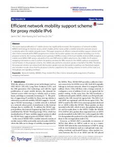
Localized mobility solutions offer efficient mobility support for mobile users. However, if a mobile user leaves the coverage of a local mobility domain, the specific mobility support breaks. As shown in Section 2, existing approaches have provided solutions by adding a global anchor point which has a constant communication with the local mobility domains. Unfortunately this solution still suffers from the aforementioned drawback of centralized control and non-optimal placement of the mobility anchor. Furthermore, such global anchor point is a single point of transit for flows from and to the MN which introduces additional scalability issues and risks of failures. To achieve the inter-domain mobility and benefit from local mobility solutions, we employ a decentralized architecture as shown in Figure 1. Instead of providing a fixed global anchor point for a MN, we reuse the anchor points provided by the local mobility solutions as global anchor points when the user leaves the local mobility domain. As show in Figure 1, a mobile user (MN) firstly attaches to a local mobility domain (PMIP Domain 1) which provides a local anchor point. We call this initial anchor point Session Mobility An-
and the new LMA are intuitionally close to each other (e.g. in the same metropolitan area or in two adjoining ASes).
5.
Figure 1: Architecture of I-PMIP
chor (SMA) because it will serve as mobility anchor for the MN until the user ends his mobility session. As long as the user moves within this domain the mobility is supported by the local mobility solution. If the user moves to another local mobility domain (PMIP Domain 2) the mobility support would break because the mobility anchor point changes. However, in our approach, the local anchor point of the domain the MN initially attached to, keeps serving as the global mobility anchor in form of the SMA. The SMA forwards all the subsequent traffic for the MN to the LMA that the MN is currently attached to. In case the MN moves to yet another mobility domain (not shown in the figure), the SMA forwards the traffic directly to that particular new LMA. In contrast to our earlier work [10] this architecture does not rely on any support by the mobile node like, for example, a SHIM layer. Instead we exploit the inherent features of network-based mobility solutions like PMIP to provide inter-domain mobility support without any involvement on the side of the mobile node.
4.1
Features
Summarized, the proposed architecture provides three noteworthy features. Independent Mobility Domains: The only interconnection between two mobility domains is through an (IP-) tunnel between the SMA and the LMA. Both domains can be under different administrative control with different local policies or charging models Inter-Domain Mobility Support: Although the local mobility domains can individually provide localized mobility support, by interconnecting them through the SMA, our architecture provides inter-domain mobility support. The inter-domain mobility support comes at no advance costs for the MN. This means that as long as the MN stays within its initial domain, no penalties are imposed on the MN. Near-Optimal Placement of Mobility Anchors: We chose the LMA that a MN initially attaches to as the global mobility anchor for a MN. We argue that this is a near optimal placement for a global mobility anchor. Before a user leaves a local mobility domain, the LMA should implicitly be placed optimally by exploiting the locality. When a mobile user moves to another domain, the movement is restricted by physical parameters. A user will physically move gradually with limited speed. Consequently we argue that the SMA
INTER-DOMAIN MOBILITY SUPPORT FOR PROXY MOBILE IP
In this section we describe how Proxy Mobile IP can be extended by the above architecture to achieve inter-domain mobility support. To correspond with regular PMIP operations as described in [7], there are no changes as long as the MN stays within the local PMIP domain. However, when it leaves the PMIP domain, the LMA will become the SMA and handle all incoming and outgoing communications for the MN during the entire mobility session. Thus, the LMA in the new PMIP domain will initiate a tunnel to the SMA to provide continuous mobility support for the MN. When the mobile user moves within the new PMIP domain, the general localized mobility operations are performed and additionally, all traffic from the MN is traversed first through the current LMA and later through the SMA. The details presented in this section are also partially available as an Internet Draft [12].
5.1
Assumptions
The I-PMIP approach is extending PMIP to provide interdomain mobility. It is based on a number of assumptions that we will introduce briefly. Working PMIP Infrastructure: Essentially, I-PMIP interconnects multiple PMIP domains to provide continuous mobility support to nodes that are moving between these domains. We assume a working PMIP infrastructure in each of those domains that we extend to support inter-domain mobility. Intra-domain mobility is provided by each of those domains based on ordinary PMIP and every entity is behaving as described in the PMIP specifications. The only exception to this is the LMA which operations are slightly changed as described further below. Inter-Operator Relationship: The different domains connected by I-PMIP can be operated by different network access providers. However, in that case, we assume that there is some kind of business and trust relationship between those operators. I-PMIP requires a level of trust between the different LMAs that is compareable to the level of trust each LMA requires from it’s corresponding MAGs. Part of such operational agreements are, for example, the conditions under which users are allowed to move between domains, authentication methods, and security associations between the LMAs. Seamless Coverage: In order to provide any kind of seamless mobility an underlying seamless network connection is required. The most prominent benefit I-PMIP offers is a continuous reachability through the same anchor point (i.e. the SMA) even when the MN moves between domains. However, if the node looses network connectivity on any layer below IP there is not much any approach based on IP can do. I-PMIP does not cache any data on behalf of the MN or keeps connections artificially alive. If the network connection is lost any existing connections are subject to timeouts.
5.2
Design Objectives
To adapt PMIP to the architecture introduced above we need to implement some extensions to the original PMIP.
This changes are guided by a number of design objectives. Minimal Changes to PMIP: For the approach to be viable we deem it indispensable to keep the changes to the original PMIP specifications as minimal as possible. This especially applies to the number of entities that need to be changed. Therefore we limit the changes to the original PMIP entities to just the LMAs. Distributed Character: Based on the proposed architecture we want to keep the approach in a distributed manner. This means that I-PMIP should not introduce any additional bottleneck or single point of failure. No Changes to the End Hosts: One of the prominent features of PMIP is that is does not require any changes to the end host. The I-PMIP approach should not change this.
5.3
Finding the Session Mobility Anchor
The biggest challenge to support inter-domain mobility using the proposed architecture is to find the corresponding SMA. When a MN attaches to a PMIP domain, the LMA of this domain has to locate the SMA for the MN. In case a MN initially attaches to a PMIP domain, the current LMA becomes the SMA and continues with its regular PMIP operations. If the MN has already been attached to a different PMIP domain and it’s SMA resides at the previous domain, the LMA has to establish a binding with the SMA in order to forward the data for the MN through its SMA. Depending on the specific scenario, the LMA can directly or indirectly locate the SMA of a MN.
5.3.1
Indirect Location
To locate a MN’s SMA without requiring any direct knowledge about the SMA, the LMA infers the SMA assigned IP address of the MN and uses this address to send a PBU to. Since the SMA is responsible for this IP address, the LMA will indirectly reach the SMA using the MN’s address. If there is no reply to the request, the LMA must assume that no SMA exists and itself become the SMA for the MN. To infer a nodes IP address the LMA can, for example, analyze a MN’s Router Solicitation messages [11] or DHCP requests [4]. Unfortunately this approach requires each SMA to analyze all it’s incoming traffic using some sort of packet inspection to recognize the corresponding PBUs. Furthermore, a LMA must wait for a timeout in case there is no SMA for a MN available yet. On top of that, there is no guaranteed method to infer a MN’s assigned address. For those reasons, the indirect location of the SMA does not seem very feasible at the moment.
5.3.2
Direct Location
To directly locate the SMA we introduce a common database which is used by all the associated PMIP domains. The database stores information about the established MN-SMA bindings from all domains. We implement this database as a virtual mobility anchor (VMA) as shown in Figure 2. The VMA is shared across all mobility domains and processes specific PBUs from their LMAs. We call it virtual since it does not relay any traffic for MNs. When a MN attaches to a PMIP domain the corresponding LMA sends a PBU to the VMA which includes the MN’s identity (e.g. its Network Access Identifier (NAI) [3] or it’s link layer address) and a flag that specifies the PBU as a SMA-PBU. If the VMA already has a binding for the MN, it forwards the PBU to the particular SMA. The SMA updates it’s own bindings and responds
Figure 2: Direct Location Example
with a Proxy Binding Acknowledgment (PBA) to the VMA which in turn sends a PBA that contains the SMA’s address to the LMA. If the VMA does not have a binding for the particular MN, it creates one and replies with a PBA that indicates that no SMA was found. The LMA then regards itself as the SMA. Admittedly, introducing a centralized database that is shared across all PMIP-domains violates the distributed character we set as a design objective. However, we argue that it is only a relatively small concession because of the lightweight character of the VMA. The VMA doesn’t forward any traffic besides PBUs and the corresponding PBAs which are transmitted when a MN attaches to a PMIP domain for the first time. Therefore, the load imposed on the VMA is not very high which prevents it from becoming a bottleneck. Moreover, it is only involved in the actual handover of a MN from one PMIP-domain to another PMIP-domain. Intra-domain movement or the data forwarding after a handoff are not affected if the VMA should fail. This alleviates the position of the VMA as a single point of failure.
6.
EVALUATION
The evaluation of our approach is conducted through theoretical analysis. We select MIP, HMIP and H-PMIP as benchmarks to be compared with our approach since they can provide inter-domain mobility support and our approach extends the standard PMIP to support inter-domain mobility.
6.1
Considered Scenario
We firstly introduce a hierarchical topology used for the following analytical study. Figure 3 depicts the considered scenario. A MN is initially attached to one domain and moves to another domain which initiates an inter-domain handover. When considering H-PMIP, the function of the MAG will be performed at the default access routers. For brevity, we assume the MAG is co-located at the MN as the delay between the MN and MAG is negligible. When HMIP is considered, the function of the MAP will be performed at the same place as LMA for fairness and simplicity. As in our approach the first attached LMA will serve as SMA. We further assume the SMA is performed at the MAP and LMA. When the mobile moves to another PMIP domain, the LMA/MAP will serve as MA in our approach.
HMIP An inter-domain handover in HMIP consists of: 1) the MN sending a BU to it’s new MAP; and 2) the MN updating the HA: HLHM IP = d(M N, HA) + d(M N, M AP2 )
(2)
H-PMIP In H-PMIP the MAG will send a PBU to the LMA prior to configuring the MN. Afterwards, the MN will update its HA. HLH−P M IP = d(M N, HA) + d(M AG, LM A2 )
(3)
I-PMIP In I-PMIP the MAG in the new domain needs to query it’s LMA and the LMA needs to query the VMA which in turn forwards the BU to the SMA. The handover latency is listed as: Figure 3: Scenario for Analytical Study
6.2
HLI−P M IP = d(V M A, SM A) + d(LM A2 , V M A) +d(M AG, LM A2 )
Assumptions and Parameters
In the following analysis, we consider the latency in the case a handover is initiated by the MN’s movement. We denote d(x, y) as the distance between the two entities x and y. The distance can be expressed, for example, as round trip time between the two entities or as message exchange. For our further evaluations we define the distance as the latency of a message exchange between the two entities. We further assume: 1. The latency introduce between the MN and its network access point is negligible. 2. The processing latency of a local trigger in the MN’s protocol stack is ignored. That is, the period used to receive a movement hint with any link-layer support is zero. 3. For simplicity we assume that the optimal deployment location of a MAP (in case of HMIP) and a LMA (in case of PMIP) in one domain is the same, i.e., d(M APi , x) = d(LM Ai , x). 4. The home agent cannot be always in a direct routing path between the CN and the MN. Therefore, the following equality is satisfied: d(CN, HA)+d(HA, M N ) >= d(CN, M N ). 5. MIP and it’s extensions offer route optimization which allows for more efficient routing between the CN and the MN. However, we do not consider route optimization in our present evaluation since it is more realistic to assume that the CN might not support MIP or any specific mobility protocols.
6.3
Handover Latency
The Handover Latency (HL) during inter-domain handovers is determined by the handover-related signaling that needs to be completed before data from the CN can be forwarded to the new location of the MN. To evaluate the approaches we determine the amount of signaling that is required for a handover. MIP: For a handover in MIP, the MN needs to update its current location to the home agent. The handover latency is formulated as HLM IP = d(M N, HA)
(1)
6.4
(4)
Data Exchange Latency
The Data Exchange Latency (DL) depends on the route the data is forwarded between a MN and its CN. To evaluate the approaches we determine the costs of the data exchange. MIP In MIP without route optimization data between the CN and the MN is exchanged via the home agent: DLM IP = d(CN, HA) + d(HA, M N )
(5)
HMIP HMIP also uses the home agent as global anchor point but further routes the data over the LMA: DLHM IP = d(CN, HA) + d(HA, M AP ) +d(M AP, M N )
(6)
H-PMIP In H-PMIP traffic is routed through the home agent via the LMA: DLH−P M IP = d(CN, HA) + d(HA, LM A) +d(LM A, M N )
(7)
I-PMIP The I-PMIP approach uses the SMA as a global anchor point and further routes data for the MN through the current LMA: DLI−P M IP = d(CN, SM A) + d(SM A, LM A) +d(LM A, M N )
6.5
(8)
Discussion
On a very basic level we can classify latency in three categories: Local latency (L) is a low latency which occurs within the same domain (e.g. d(M AG, LM A)). Regional latency (R) is noticeable but limited latency and occurs within a constricted geographical region (e.g. d(LM A, V M A)). Global latency (G) is a high latency and is introduced, for example, by inter-continental links (e.g. d(M N, CN )). We assume that G > R > L. Table 1 shows the result of a classification of the distances in the Formulas 1 to 8 into these categories. Judging the relation of the two regional updates I-PMIP needs (d(LM A, V M A) + d(V M A, SM A)) to the one global update which is needed by the other solutions is difficult. We argue that through the proximity of the VMA to the SMA and LMA this costs are kept within in a limit. For example, if the database is distributed through different networks, the latency between LMA and the VMA as well as between VMA and SMA can be assumed low.
Table 1: Comparison of Handover and Data Exchange Latency Approach MIP HMIP H-PMIP I-PMIP
Handover Lat. 1G 1G+1L 1G+1L 2R+1L
Data Exchange Lat. 2G 2G+1L 2G+1L G+R+L
A comparison of the date exchange latency among the above approaches is difficult because the latency heavily depends on the location of the specific nodes. We therefore make both best-case and worst-case considerations. The best-case scenario for MIP is that the HA is the default gateway for the CN. In this case there is no additional latency compared to the normal data delivery to the MN. The same argument is valid for HMIP and PMIP in case the MAP/LMA is the topologically logical default gateway for the MN (for HMIP additionally to the HA being the default gateway for the CN). The best-case for I-PMIP would occur if the SMA is the default gateway for the CN and the LMA is the topologically logical default gateway for the MN. The worst-case for MIP is when the latency d(CN, HA) and d(HA, M N ) in (5) are maximized. That is, both the CN and the MN are far away from the HA. HMIP is comparable to MIP since d(M AP, M N ) can be locally optimized when d(HA, M AP ) + d(M AP, M N ) will only occur little overhead compared to d(HA, M N ). The same local optimizations can be performed for PMIP which brings the worst-case scenario for PMIP close to it’s best-case scenario. However, in a very large PMIP deployment the LMA might not be always positioned topologically optimal for each MN. In the I-PMIP approach the same local optimization can be used for d(LM A, M N ) which leaves d(SM A, LM A). Since the SMA is located in the domain the MN was initially attached to and the LMA is located in the domain the MN is currently attached to, d(SM A, LM A) is bound to the latency the mobile user has traversed through from its initially attached domain. Although the physical distance cannot be directly comparable to the topological distance, we argue that the toplogical distance is somewhat small, for example, neighboring ASes. In summary, we believe that I-PMIP has handover latency that is comparitive to the other approaches but that its data exchange latency is superior. Moreover, I-PMIP is a purely network-based approach which means that, in contrast to MIP-based solutions, no changes are required in the MN.
7.
CONCLUSION AND FUTURE WORK
In this paper we have proposed an extension to PMIP, called I-PMIP, which allows to interconnect multiple PMIPenabled mobility domains to provide a continuous mobility support to a MN if it moves between those domains. The IPMIP architecture provides an implicit near-optimal placement of the anchor point for a MN and has a distributed character which does not introduce additional bottlenecks or single point of failures. Furthermore, I-PMIP inherits the features of a network-based mobility solution from PMIP, in particular it doesn’t require any changes or configuration of the end host or a dedicated mobility provider for the mobile
user. A numerical analysis shows that our network-based approach is comparably efficient in terms of handover latency and data delivery costs to host-based mobility solutions like MIP, HMIP or H-PMIP. As future work, we will improve the localization of the SMA by using a distributed database among the LMAs. We are also investigating how to apply the basic architecture of our approach to other network-based mobility solutions. Moreover, we are implementing I-PMIP in the OMNeT++ simulation framework using real-world topology data to further validate and optimize our approach.
8.
REFERENCES
[1] Universal Mobile Telecommunications System (UMTS); Architecture enhancements for non-3GPP accesses. ETSI TS 123 402 v8.3.0(2008-10), 2008. [2] Universal Mobile Telecommunications System (UMTS); General Packet Radio Service (GPRS) enhancements for Evolved Universal Terrestrial Radio Access Network (E-UTRAN) access. ETSI TS 123 401 v8.3.0(2008-10), 2008. [3] B. Aboba, M. Beadles, J. Arkko, and P. Eronen. The Network Access Identifier. RFC4282, 2005. [4] R. Droms, J. Bound, B. Volz, T. Lemon, C. Perkins, and M. Carney. Dynamic Host Configuration Protocol for IPv6 (DHCPv6). RFC3315, 2003. [5] A. Dutta, S. Das, H. Yokota, T. Chiba, and H. Schulzrinne. ProxyMIP Extensions for Inter-MAG Route Optimization. draft-dutta-netlmm-pmipro-01, 2008. [6] G. Giaretta. Interactions between PMIPv6 and MIPv6: scenarios and related issues. draft-ietf-netlmm-mip-interactions-01, 2008. [7] S. Gundavelli, K. Leung, V. Devarapalli, K. Chowdhury, and B. Patil. Proxy Mobile IPv6. RFC5213, 2008. [8] D. Johnson, C. Perkins, and J. Arkko. Mobility Support in IPv6. RFC 3775, 2004. [9] J. Kempf, K. Leung, P. Roberts, K. Nishida, G. Giaretta, and M. Liebsch. Problem Statement for Network-based Localized Mobility Management. RFC 4830, 2007. [10] D. Le, J. Lei, and X. Fu. A New Decentralized Mobility Management Service Architecture for IPv6-based Networks. In WMuNeP ’07: Proceedings of the 3rd ACM workshop on Wireless multimedia networking and performance modeling, pages 54–61, New York, NY, USA, 2007. ACM. [11] T. Narten, E. Nordmark, W. Simpson, and H. Soliman. Neighbor Discovery for IP version 6 (IPv6). RFC4681, 2007. [12] N. Neumann, X. Fu, J. Lei, and G. Zhang. Inter-Domain Handover and Data Forwarding between Proxy Mobile IPv6 Domains. draft-neumann-netlmm-inter-domain-01 (work in progress), Jan. 2009. [13] H. Soliman, C. Castelluccia, K. E. Malki, and L. Bellier. Hierarchical Mobile IPv6 Mobility Management (HMIPv6). RFC 4140, 2005.