RZ 3738 (#996748) 06/03/09 Computer Science 118 pages
Research Report IBM Pattern-based Process Model Accelerators for WebSphere Business Modeler Thomas Gschwind (
[email protected]) Research Staff, IBM Zurich Research Laboratory Jana Koehler (
[email protected]) Research Staff Manager, IBM Zurich Research Laboratory Janette Wong (
[email protected]) Senior Technical Staff Member, IBM Software Group, Markham, ON, Canada Cedric Favre (
[email protected]) PhD Student, IBM Zurich Research Laboratory Wolfgang Kleinoeder (
[email protected]) Research Emeritus, IBM Zurich Research Laboratory Alexander Maystrenko (
[email protected]) PhD Student, IBM Zurich Research Laboratory Krenar Muhidini Student, Jacobs University Bremen, Germany
LIMITED DISTRIBUTION NOTICE This report will be distributed outside of IBM up to one year after the IBM publication date. Some reports are available at http://domino.watson.ibm.com/library/Cyberdig.nsf/home.
IBM
Research Almaden · Austin · Beijing · Delhi · Haifa · T.J. Watson · Tokyo · Zurich
IBM Pattern-based Process Model Accelerators for WebSphere Business Modeler Thomas Gschwind (
[email protected]) Research Staff, IBM Zurich Research Laboratory Jana Koehler (
[email protected]) Research Staff Manager, IBM Zurich Research Laboratory Janette Wong (
[email protected]) Senior Technical Staff Member, IBM Software Group, Markham, ON, Canada Cedric Favre (
[email protected]) PhD Student, IBM Zurich Research Laboratory Wolfgang Kleinoeder (
[email protected]) Research Emeritus, IBM Zurich Research Laboratory Alexander Maystrenko (
[email protected]) PhD Student, IBM Zurich Research Laboratory Krenar Muhidini Student, Jacobs University Bremen, Germany
Abstract R R IBM Pattern-based process Model Accelerators for WebSphere Business Modeler are a set of features designed specifically for users who create and edit process models using WebSphere Business Modeler. The accelerators provide users with a set of plug-ins for IBM WebSphere Business Modeler V6.2 that add patterns, transformations and refactorings to the business process modeling environment. In addition, a feature to automatically detect control-flow errors is now available. By using the accelerators users can move away from a traditional business process modeling approach where process models are drawn by dragging and dropping elements on the drawing canvas that are then manually connected. The accelerators make it possible to create business process models of higher quality by composing them from larger building blocks or by applying semantically correct change operations to a model with a single click. Models will contain significantly less modeling errors, modeling becomes a much more fun exercise and users will experience productivity gains of about 70% compared to the traditional approach. This technical report contains a series of 4 articles that provide users with detailed documentation of the accelerators. Part 1 of this article series contains a tutorial that gives an overview of how to work with the accelerators while modeling a business process. Part 2 presents the business process patterns that are available in this release, while Parts 3 and 4 explain process model transformations and refactorings in detail.
Copyright and trademark information IBM, the IBM logo and ibm.com are trademarks of International Business Machines Corp., registered in many jurisdictions worldwide. Other product and service names might be trademarks of IBM or other companies. A current list of IBM trademarks is available on the Web at ”Copyright and trademark information” at www.ibm.com/legal/copytrade.shtml.
IBM Pattern-based Process Model Accelerators for WebSphere Business Modeler Part 1: Understand Process Patterns and Quality & Change Management during Process Modeling Level: Introductory Thomas Gschwind (
[email protected]), Research Staff Member, IBM Jana Koehler (
[email protected]), Research Staff Manager, IBM Janette Wong (
[email protected]), Senior Technical Staff Member, IBM Cedric Favre (
[email protected]), Pre-Doctoral Researcher, IBM Wolfgang Kleinoeder (
[email protected]), Research Emeritus, IBM Alexander Maystrenko (
[email protected]), Pre-Doctoral Researcher, IBM Krenar Muhidini, Student, Jacobs University Bremen, Germany This article series walks you through the IBM Pattern-based Process Model Accelerators V2.0 for WebSphere Business Modeler, a set of plug-ins for IBM WebSphere Business Modeler that add patterns, transformations, and refactorings to your business process modeling environment. In Part 1 of this article series, you will learn in a tutorial how to compose your business process model by instantiating predefined patterns, how to automatically detect control-flow errors, and how to apply complex changes to your model with a single click by invoking a transformation or refactoring.
Introduction This Tutorial is Part 1 of a series of 4 articles introducing IBM Pattern-based Process Model Accelerators for WebSphere Business Modeler. The accelerators, as we will call them from now on, provide you with a set of plug-ins for IBM WebSphere Business Modeler that add patterns, transformations and refactorings to your business process modeling environment. In addition, a feature to automatically detect control-flow errors is now at your disposal. By using the accelerators you move away from a traditional business process modeling approach where process models are drawn by dragging and dropping elements on the drawing canvas that are then manually connected. The accelerators enable you to create business process models of higher quality by composing them from larger building blocks or by applying semantically correct change operations to your entire model with a single click. Your models will contain significantly less modeling errors, modeling becomes a much more fun exercise and you will experience productivity gains of about 70 % compared to the traditional approach. In this tutorial, you will walk step-by-step through a modeling scenario that introduces you to 5 patterns, 5 transformations, and 3 refactorings. In total, this release of the
1
accelerators contains 8 patterns, 10 transformations and 7 refactorings. Parts 2, 3 and 4 of this article series provide you with detailed documentation of all accelerators.
Prerequisites and Installation of the Accelerators In this article, we assume that you have basic knowledge of WebSphere Business Modeler, i.e., that you are familiar with the product and you have gained some modeling experience while creating business process models. You should also be familiar with the basic model elements such as gateways, tasks, subprocesses, and start and terminate events from the Business Process Modeling Notation (BPMN) as available in WebSphere Business Modeler. The help available in WebSphere Business Modeler provides you with the necessary background. In order to repeat the steps in this article, you need • • • •
IBM WebSphere Business Modeler V6.2.0 Fixpack 1 for IBM WebSphere Business Modeler V6.2.0, i.e., you are using V6.2.0.1 of the product the accelerator.zip file provided for download together with this article an example modeling project HiringExample.mar
Download the accelerator.zip file to your computer. Unzip the file to a directory, e.g., C:\temp\acceleratorUpdatesite.The file contains a local Eclipse update site. By using an update site, you can properly manage the configuration of your WebSphere Business Modeler installation. To install the accelerators in WebSphere Business Modeler V6.2, perform the following steps: 1. Start WebSphere Business Modeler Basic or Advanced V6.2. 2. Select Help > Software Updates … 3. Click on the Available Software tab as is shown next.
2
4. Click on Add Site… In the window that opens, click on Local… as is shown next. A browser window opens that allows you to navigate to the unzipped update site in your file system, e.g., browse to file:/C:\temp\acceleratorUpdatesite. The file location will be added as the Location. Click OK to close this window.
5. The local update site will be added to the Available Software tab. You should see the following WBM Extensions listed.
3
6. Mark the check box in front of WBM Extensions as is shown next. Then click on Install … in the upper right corner of the window.
7. Eclipse will calculate requirements and dependencies. This can take a while. You should see an Install window opening. If you encounter problems, verify that you have WebSphere Business Modeler V 6.2 with Fixpack 1 installed. 8. Make sure that all features are marked and click Next. Accept the terms in the licence agreements, click Next again, then click Finish. When prompted for verification, click on Install All. The accelerators will be added to your installation of WebSphere Business Modeler. 9. You will be asked to restart WebSphere Business Modeler. Answer Yes.
To uninstall the accelerators properly, scroll down the Installed Software Tab that opens when you select Help > Software Updates … in WebSphere Business Modeler and search for WBM Feature in the Installed Software tab. Select all WBM Features that you want to uninstall and click on Uninstall … Review and Confirm that you want to uninstall the checked items that are listed in the next view, then click Finish.
How to Invoke the Accelerators in WebSphere Business Modeler 6.2 After successful installation of the accelerators and a restart of WebSphere Business Modeler, verify that the accelerators are available in your modeling environment. Apply the 4-Pane Layout in WebSphere Business Modeler such that you can see the Project Tree view in the upper left, the drawing palette and canvas in the upper right, the Outline view in the lower left, and the Attributes view in the lower right of the tool. Import the HiringExample.mar file into WebSphere Business Modeler into a project that you name HR Processes. In the project tree view, you should see the following content.
4
Select a process catalog or one of the processes in the Project Tree and with a right click invoke the pull-down menu. You should see a new entry Control-Flow Analysis at the bottom of this menu.
5
Open one of the business process models. The process will open on your drawing canvas. Make sure that you are viewing the process in Free-Form Layout. Click right anywhere in the white space of your drawing canvas and invoke the pulldown menu. At the bottom of this menu, you should see the Control-Flow Analysis, followed by the Pattern, Transform, and Refactor submenus.
While the Control-Flow Analysis is available to you in Free-Form Layout as well as in Swimlane Layout, the patterns, transformations, and refactorings are only available in Free-Form Layout. Open Window > Show View > Other … in WebSphere Business Modeler. In the Show View window that opens, expand the Business Modeler Views folder. Select the Accelerators Palette and click OK.
6
A palette with icons for all accelerators is added to your attributes view at the bottom of WebSphere Business Modeler. You can see a description of each icon when you hover with your mouse over the icon. By clicking on an icon, you can invoke an accelerator. You can also detach the palette from the view or attach it elsewhere in WebSphere Business Modeler. Furthermore, the palette names and entries can be configured. We will describe how to detach and configure the palette in Part 2 of this article series.
Overview of the Example Modeling Scenario When importing the HiringExample.mar file, you created a modeling project named HR Processes that was added to your project tree. It contains three business items Application, Contract, and Employee Record and the following process models in a process catalog named Hiring • • •
Approve Hire and Issue Contract – Final Version Evaluate Candidate – Faulty Version Evaluate Candidate – Final Corrected Version
7
• •
Handle Signed Contract – Control Flow Only Handle Signed Contract – Final Version Data Flow
The processes in the Hiring catalog show the final versions of the process models that you will create and/or change in this tutorial. We suggest that you do not work directly on these process models to keep them unchanged for your reference. In this tutorial, we will create new versions of all processes in a process catalog named Exercise that we create in the default Processes catalog.
Composing the Approve Hire and Issue Contract Process from Patterns Click right on the Processes catalog in the project tree and select New > Process Catalog. Name the new process catalog Exercise and click Finish. Create a new process model in the Exercise process catalog and name it Approve Hire and Issue Contract.
8
A process diagram opens that contains a disconnected start and terminate event. Connect the two events and select the connection as is shown next.
Invoke the Sequence pattern either from the Accelerators palette by clicking on the icon or by invoking the pull-down menu with a right-click on the drawing canvas and selecting Pattern > Sequence … A wizard as is shown in Figure 1 opens. Note that you must have a connection selected in order to successfully apply a pattern! To ensure that your selected connection remains selected when you invoke the pattern, do not move your mouse after you clicked on the connection to select it. Figure 1. Wizard of the Sequence Pattern. 9
The upper part of the wizard in Figure 1 shows a picture of the pattern illustrating the process fragment structure that you can create by using this pattern. Below the picture, you find a short description of the pattern followed by a table where you can enter the pattern parameters. A pattern consists of a number of connected tasks and optional gateways. To apply the pattern, you define the names of the tasks and if you want to connect them by data flow, you additionally specify any business item(s) and optionally the business item state(s). In this tutorial, we will only instantiate patterns with task names and therefore focus on control flow only. Please refer to Part 2 of this article series to learn how to correctly specify business items and states to create patterns with data flow. Note that in the pattern wizard, the start event is shown in the first row of the table in the Task Name column. In this table cell, the pattern wizard will always show the name of the model element from which your selected connection originates. Instantiate the Sequence pattern as is shown next, i.e., enter the task names Issue Contract and Mail Contract to Future Employee in the second and third row of the first column. Then click on Apply Pattern.
10
A sequence of these two tasks is added to your process refining the selected connection.
This creates an initial simple process that you will now further refine by applying more patterns. The process will begin with a loop where the employee data is reviewed and, if necessary completed, followed by two approval steps where the contract is approved by management and human resources. Select again the connection leaving the start event and invoke Pattern > Loop … or click on the icon in the Accelerators palette. The Loop pattern wizard is shown in Figure 2.The picture shows you the overall structure of a loop fragment. It begins with a merge, followed by a number of body tasks that connect to a decision. The decision has an exit branch that terminates the loop and a loop branch that reconnects back to the merge. On the loop branch, a number of rework tasks can be specified. Three tabs are provided by the wizard 1. Loop Parameters 2. Loop Body Tasks 3. Rework Tasks Figure 2. Wizard of the Loop Pattern.
11
In this tutorial, we will only specify the name of the decision and the names of the exit and loop branches. Enter Data Complete and Accurate? in the Decision Name field, Yes in the Exit Branch Name field and No in the Loop Branch field as is shown next.
12
Then open the Loop Body Tasks tab. In the Task Name column, you see Merge as the task name in the first row, because the loop body always starts in the merge gateway. In the second row, enter Review Employee Data as the task name as is shown next.
Open the Rework Tasks tab. In this tab, you see the name of the Loop Branch shown as the task name in the first row. Enter Return to Submitting Manager as the name of the rework task in the second row as is shown next. Then click on Apply Pattern.
Invoke Auto-Layout from Left to Right from the pull down menu that you get when clicking right on the drawing canvas to improve the layout of the generated process. Your process should now look as in Figure 3. Figure 3. The Approve Hire and Issue Contract process after applying the Sequence and Loop patterns.
Now add the required management approval tasks. Select the Yes branch of the Data Accurate and Complete? decision as is shown next.
13
Invoke Pattern > Parallel Compound … or click on the icon in the Accelerators palette. This pattern allows you to add tasks to your process model that should be performed in parallel. The wizard of the Parallel Compound pattern opens as is shown in Figure 4. Figure 4. Wizard of the Parallel Compound Pattern.
14
A Parallel Compound is a number of tasks each occurring on a separate branch, which start in a fork gateway and end in a join gateway. In the table provided by the wizard you specify the names of these tasks. Enter Obtain Management Approval as the task name in the first row and Obtain HR Approval as the task name in the second row as is shown next. Then click on Apply Pattern.
Your process should now look as is shown in Figure 5. Recall that we modeled it by instantiating 3 patterns: Sequence, Loop, and Parallel Compound. Figure 5. Final version of the Approve Hire and Issue Contract process.
Applying Fast Changes through Transformations and Refactorings when Creating the Handle Signed Contract Process When creating our next example process Handle Signed Contract, we will use some of the transformations and refactorings that are provided by the accelerators together with two more patterns. In the Exercise process catalog, create a new process and name it Handle Signed Contract. Create the following tasks • Receive Signed Contract • Verify Necessary Signatures • Contact Employee and Complete Data • Obtain Social Security Information
15
•
Check Work Permit Status
Place the tasks and the start and terminate events on the drawing canvas as is shown next. Note that we placed three of the tasks in an approximate row, while the other two tasks were placed in an approximate column with sufficient extra white space between the column and the tasks in the row. Imagine that a gateway could be placed there.
Invoke Transform > Autolink Elements or click on the icon in the palette. Control-flow connections are automatically added to your model. Apply the Auto-Layout, name the decision All Documents Filled In and Signed? and name its output branches Yes and No. Then save your model. It should look as is shown next.
The Autolink Elements transformation automatically connects tasks based on their geometric position on the drawing canvas. It also inserts decision and merge gateways when you indicate alternative branches by placing tasks in a column and leaving sufficient white space before and after a column of tasks. You can also apply this transformation to only a selected set of model elements and thereby use it to create complex models. This means, you autolink a few elements, then place additional elements on the canvas, autolink them again with the already linked process fragment and so on. Refer to Part 3 of this article series for further details. The process model is not as accurate as we would like it to be. For example, we only need to check the work permit status of foreigners, but for non-foreigners we obtain their social security information. To change the process accordingly, press SHIFT and select
16
the Obtain Social Security Information and Check Work Permit Status tasks. Invoke Transform > Convert to Alternative Compound or click on the icon with both tasks selected. Apply the Auto-Layout. Your process fragment will change as is shown next.
The two selected tasks are placed on two different branches opened by a decision and closed by a merge. Change the name of the decision to Foreign National?. Enter No as the name of its upper output branch and Yes as the name of its lower output branch. The Convert to Alternative Compound transformation allows you to quickly reorder sequences of tasks such that they are placed on different alternative branches of your process model. Refer to Part 3 of this article series for further details. With our next editing step, we want to introduce an additional branch to obtain work permits in case the Check Work Permit Status task reveals that a foreign national needs a work permit. Press SHIFT and select the outgoing connection of the Check Work Permit Status task first, then select the outgoing connection of the Obtain Social Security Information task as is shown next.
17
Apply Pattern > Alternative Branch or click on the icon in the palette. Apply the Auto-Layout. A new decision-merge branch is added to your model as is shown next.
Name the new decision Work Permit Holder?. Name its upper branch Yes, its lower branch No. Then select the lower branch as is shown next.
icon in the palette. A new task is Invoke Pattern > Insert Task or click on the added to the No Branch of the Work Permit Holder? decision. Name this task Request Work Permit.
18
Two make your process model tidier, select the two merge gateways and invoke Transform > Merge Elements or click on the
icon.
The two selected gateways are merged into a single gateway and the control flow is properly reconnected. The process model is now changed as is shown next. In you’re your model shows incoming connections into the merge that cross each other, try Refactor > Automatically Order Branches or click on the icon in the palette. The Automtically Order Branches refactoring can help to improve the layout of your model if a slight repositioning of the merge gateway on the canvas does not have the desired effect.
Finally, select the incoming connection of the terminate event and apply the Sequence pattern to add two more tasks Create Employee Record and Prepare Welcome Package at the end of the process.
19
Your process is now completely modeled. Recall that we applied the Autolink Elements Transformation, followed by the Convert to Alternative Compound transformation, followed by the Alternative Branch and Insert Task patterns. Then we applied the Merge Elements transformations, followed optionally by the Automatically Order Branches refactoring. Finally, we applied the Sequence pattern. With these 7 accelerators, we modeled a quite complex process in a fast and accurate manner. To verify that your process has no control flow errors, run the Control-Flow Analysis. It will confirm that your process is correct.
It is a recommended modeling practice to use subprocesses to obtain a better structure for large process models. A subprocess encapsulates a connected fragment of the process containing tasks and gateways and is properly connected to the surrounding parent process. The accelerators help you to quickly add subprocesses to your model with the control flow between the new subprocess and the parent process being properly restored. Select the process fragment that starts in the Foreign National? decision and ends before the terminate event as is shown next. To keep this fragment selected when you invoke the next refactoring, purposefully position the cursor on one of the selected elements in order to ‘preserve’ your selection.
20
Invoke Refactor > Extract Subprocess or click on the icon. A new subprocess is created and opened on the drawing canvas. The selected process fragment is moved into this subprocess. The Handle Signed Contract process now contains a subprocess as is shown next.
Name this subprocess Create Work Documents. Now, add data flow to the Handle Signed Contract process model. When doing traditional modeling, you have to select each connection and invoke Associate Data ….Select the last connection in the process model connecting the Create Work Documents subprocess to the terminate event. Use the traditional Associate Data… to associate the connection with the Employee Record business item. Imagine that you had to do this for each connection in your process model. This would be quite cumbersome. With the new Associate Data transformation, you can now easily associate data with multiple connections through one single operation. Select all the other connections of your process model, e.g., by holding the left button of your mouse pressed and pulling it over the fragment of the process model that begins with the start event and ends with the connection leading to the Create Work Documents subprocess. Note that the subprocess itself is not selected as is shown next.
21
Now invoke Transform > Associate Data … or click on the icon making sure to preserve your selection. A window opens that allows you to browse to all available business items. Click the Complex type radio button and select the Contract business item as is shown next. Then click OK.
Data flow is assigned to the Handle Signed Contract process. With this last transformation, you have completed the model of this process.
To add data flow to the Create Work Documents subprocess, open this subprocess in a new page and apply the Associate Data … transformation as desired. To match the data flow in the Handle Signed Contract process, the Create Work Documents subprocess should take a Contract as input and provide an Employee Record as output. You can achieve this by applying the Associate Data … transformation twice. 22
Detecting Modeling Errors and Repairing the Evaluate Candidate Process Many traditionally created process models contain modeling errors. When dragging and dropping single graphical model elements on a canvas, users often lose sight of the control flow that they design when connecting the single model elements and adding gateways to their process model. When creating a process model using the accelerators, notably the patterns, you cannot introduce modeling errors into your model. However, on traditionally created models, the accelerators help you to easily detect and locate errors in those models. Furthermore, they provide you with means to quickly correct modeling errors. Copy the Evaluate Candidate-Faulty Version process from the Hiring process catalog to the Exercise process catalog and open it in the editor. The Evaluate Candidate process describes the evaluation and interview process for an applicant applying for a student internship or researcher position as it is used by the research team co-authoring this article. It was modeled in the traditional way without using any patterns or refactorings and transformations. Unfortunately, it contains two control-flow errors. The initial part of this process looks as is shown in Figure 6.The first task in this process is Receive Application that captures the arrival of an application folder in the team. The task is followed by the Check CV task to examine the curriculum vitae of the applicant. Then, a fork gateway follows that opens three parallel branches. The upper branch contains the Review Selected Publications task where available publications of the candidate are examined and some are selected for further review. The middle branch contains the Examine Qualification Profile task to check whether the skill profile of the candidate matches the skills needed by the team. The lower branch contains the Check Grades & Certificates task that looks at the formal documents included in the application. The three branches are closed by a merge gateway. Figure 6. Initial part of the Evaluate Candidate process.
23
The final part of the Evaluate Candidate process contains three decision gateways. If the candidate looks promising after the initial reviews, an exercise is sent to him to test his technical and collaboration skills. If the candidate worked well on the exercise, an interview is scheduled. If the interview went also well, the candidate is usually accepted. In all other cases, the candidate is rejected, i.e., the three No branches of the decisions enter the Reject task at the end of the process model.
Each part of this process contains a very typical modeling error that usually happens when models are created in the traditionally way. Click right on the Evaluate Candidate process in the project tree and invoke the Control-Flow Analysis from the menu. Alternatively, click right on the white space of the drawing canvas and invoke ControlFlow Analysis from the menu that is associated with the drawing canvas. A new view is added at the bottom of WebSphere Business Modeler containing an error message as is shown next.
Click at the plus sign (+) in front of the error message to view further details. More detailed error descriptions inform you about the type of error (lack of synchronization or deadlock) and the location of the error in some fragment of the process.
Our example process contains a lack of synchronization error in the initial part that is caused by the fork and detected on the merge. The final part of this process contains a deadlock that is detected on the Reject task. By double-clicking on an error message the fragment containing the error is colored red, see Figures 7 and 8 below.
24
A Lack of Synchronization Modeling Error A lack of synchronization is an error where two or more parallel branches are not correctly synchronized in the process model. It has the effect that all tasks following the insufficient synchronization are executed more often than intended. In our example, the fork gateway opens three parallel branches that are synchronized by a merge gateway. The merge waits for one branch to finish and then continues to route the flow to the final part of the process. This means, for each branch entering the merge, the final part of the process will be executed once, i.e., three times in total. Of course, this is not the intended process behavior. Figure 7. A Lack of Synchronization error marked in the Evaluate Candidate process model.
A Deadlock Modeling Error A deadlock is a modeling error that causes the control flow to stop at some task or gateway in the process model because the task or gateway waits for some input that can never arrive. In our example, the Reject task waits for three control inputs from each of its incoming connections. However, always only one of the three required control flow inputs is activated in any execution of the process, because the three decision gateways always activate exactly one of their output branches. The control flow will therefore stop at the input of the Reject task that can never execute. Each decision in our example process opens two exclusive branches of which either only the Yes or the No branch is taken. For example, if the first decision activates the No branch, the other two decisions are no longer taken as the control directly proceeds to the Reject task. It is therefore impossible that the Reject task can receive all three No inputs at the same time. Figure 4. A Deadlock error marked in the Evaluate Candidate process model.
25
You can observe this problematic behavior of the process caused by these two types of errors by simulating your process model with WebSphere Business Modeler. To read more about modeling errors, have a look at articles by J. Koehler and J. Vanhatalo listed in the Resources section at the end of this article. Recall that the Control-Flow Analysis detected two errors in the Evaluate Candidate process 1. A lack of synchronization caused by pairing a fork gateway with a merge gateway. 2. A deadlock caused by a task that expects three inputs coming from alternative branches. To identify the gateway causing the lack of synchronization, examine the affected process fragment. The fork is correct, because we want to execute all three tasks in parallel. Consequently, the merge must be replaced by a join that correctly matches the fork.
To correct, the lack of synchronization error, select the merge and invoke Transform > Toggle Gateways or click on the icon in the palette. The merge will be replaced by a join. Save the process model and then run the Control-Flow Analysis again – the error is no longer reported.
26
Select either the fork or the join and run the Toggle Gateways transformation again. It will now toggle both gateways simultaneously, i.e., the fork is changed to a decision and the join is changed to a merge. The reason for this behavior is the following: When you toggle a gateway that is part of a process fragment that contains an error, only the selected gateway is toggled. When you select a gateway that is paired with one or more correctly matching gateway(s), the set of matching gateways is always toggled together to ensure that you do not introduce a modeling error into your model when toggling gateways. In a nutshell, the Toggle Gateways transformation allows you to correct errors caused by gateways, but it will always ensure that you do not transform a correct model into an incorrect one. See Part 3 of this article series for further details. To correct the deadlock error, first make the error more explicit. Select the Reject task and invoke Refactor > Activity to Gateway Form or click on the palette.
icon in the
The three connections that lead directly to the Reject task are converted to a join with three incoming connections and a single outgoing connection that leads to the task. The
27
Activity to Gateway Form refactoring provides you with a correct translation of the input and output logic of a task into the corresponding gateways. See Part 4 of this article series for further details. We can now see that the outgoing flow of the three decisions is incorrectly matching the join gateway.
Select the join and invoke Transform > Toggle Gateways again to toggle the join into a merge. Save the corrected model and run the Control-Flow Analysis again. No error is reported anymore!
Summary This article introduces you to the IBM Pattern-based Process Model Accelerators for WebSphere Business Modeler that provide you with patterns, transformations and refactorings. Instead of modeling in a traditional way by placing tasks and gateways on the drawing canvas and connecting them one by one, you learn how to apply patterns to create entire process fragments and to apply transformations and refactorings to your model that encapsulate complex editing operations in a single click. In addition to the time savings that you experience, you also learn how to automatically detect and correct modeling errors in the control flow of a business process model. Parts 2, 3, and 4 of this article series provide a complete overview over the available patterns, transformations, and refactorings that are available in this release of the accelerators.
Resources
IBM Pattern-based Process Model Accelerators for WebSphere Business Modeler Part 2: Advanced Use of Patterns and Configuration of the Accelerators Palette, IBM DeveloperWorks, forthcoming 2009.
IBM Pattern-based Process Model Accelerators for WebSphere Business Modeler Part 3: Master Process Model Change with Ready-to-Use Transformations, IBM DeveloperWorks, forthcoming 2009.
28
IBM Pattern-based Process Model Accelerators for WebSphere Business Modeler Part 4: Improve Process Models through Refactoring IBM DeveloperWorks, forthcoming 2009.
To access all articles of this series, download the accelerators and the example file, and to watch this tutorial as a video follow this link http://www.ibm.com/developerworks/websphere/library/techarticles/0901_wong/ 0901_wong.html?ca=drs--
N. Russell, A.H.M. ter Hofstede, W.M.P van der Aalst, and N. Mulyar: Workflow Control-Flow Pattern Library: A revised View. BPM Center Report BPM-6-22, BPMcenter.org, 2006. See also www.workflowpatterns.com.
Tutorials and Samples for WebSphere Business Modeler Version 6.2: Learn about business process modeling with WebSphere Business Modeler V6.2 and download additional example models.
WebSphere Business Process Management V6.2 Information Center: Access more information about Business Process Management with WebSphere V6.2.
T. Gschwind, J. Koehler, J. Wong: Applying Patterns during Business Process Modeling. Proceedings of the 6th Intern. Conference on Business Process Management, LNCS 5240, pages 4-19, Springer 2008.
R. Kong: Modeling business processes in WebSphere Business Modeler for BPEL transformation, IBM developerWorks, January 2008.
J. Koehler, J. Vanhatalo: Process anti-patterns: How to avoid the common traps of business process modeling, Part 1: Modeling Control Flow, IBM developerWorks, February 2007.
J. Koehler, J. Vanhatalo: Process anti-patterns: How to avoid the common traps of business process modeling, Part 2: Modeling Data Flow, IBM developerWorks, April 2007.
29
IBM Pattern-based Process Model Accelerators for WebSphere Business Modeler Part 2: Advanced Use of Patterns and Configuration of the Accelerators Palette Level: Intermediate Thomas Gschwind (
[email protected]), Research Staff Member, IBM Jana Koehler (
[email protected]), Research Staff Manager, IBM Janette Wong (
[email protected]), Senior Technical Staff Member, IBM Cedric Favre (
[email protected]), Pre-Doctoral Researcher, IBM Wolfgang Kleinoeder (
[email protected]), Research Emeritus, IBM Alexander Maystrenko (
[email protected]), Pre-Doctoral Researcher, IBM Krenar Muhidini, Student, Jacobs University Bremen, Germany This article series walks you through the IBM Pattern-based Process Model Accelerators V2.0 for WebSphere Business Modeler, a set of plug-ins for IBM WebSphere Business Modeler that add patterns, transformations, and refactorings to your business process modeling environment. In Part 2 of this article series we introduce you to an advanced use of patterns where you apply patterns with business items and business item states to create pattern-based process models with data flow. We also explain to you how to configure the Accelerators palette according to your needs.
Introduction This article is Part 2 of a series of 4 articles introducing IBM Pattern-based Process Model Accelerators for WebSphere Business Modeler. The accelerators, as we will call them from now on, provide you with a set of plug-ins for IBM WebSphere Business Modeler that add patterns, transformations and refactorings to your business process modeling environment. In addition, a feature to automatically detect control-flow errors is at your disposal. By using the accelerators you move away from a traditional business process modeling approach where process models are drawn by dragging and dropping elements on the drawing canvas that are then manually connected. The accelerators enable you to create business process models of higher quality by composing them from larger building blocks or by applying semantically correct change operations to your entire model with a single click. Your models will contain significantly less modeling errors, modeling becomes a much more fun exercise and you will experience productivity gains of about 70 % compared to the traditional approach. In this article, we provide you with:
1
• •
a systematic description of the 8 patterns available in this release of the accelerators, and instructions on how to configure the Accelerators palette according to your modeling needs.
A pattern encapsulates a simple and elegant solution to a specific, but frequently reoccurring problem. Patterns are created by observing (or “mining”) a variety of solutions that different people have created over time when working on the same problem. The pattern encapsulates the “essence” that is common to all these different solutions and that ensures that the solution solves the problem. Examples of famous collections of patterns are the object-oriented design patterns by Gamma et al, the software architecture patterns by Buschmann et al, and the workflow patterns by van der Aalst et al (see Resources for detailed references). The business process patterns that we provide in this release of the accelerators encapsulate typical process model fragments that occur again and again in business process models. The encapsulated fragments represent common and easy-to-reuse control-flow structures that can also be associated with business items and business item states. When composing a process from these patterns, it is guaranteed that the process correctly executes in a process simulation environment such as the one provided by WebSphere Business Modeler and that it can be mapped to a combination of workflow patterns for a correct implementation in a process runtime engine. We cover the following patterns in this article: 1. Insert Task 2. Insert Process 3. Sequence 4. Alternative Compound 5. Parallel Compound 6. Loop 7. Alternative Branch 8. Parallel Branch The list above also introduces you to the icons of these patterns as you find them in the Accelerators palette.
2
Prerequisites This article is Part 2 of an article series and we assume that you are familiar with Part 1 of this article series. This means, • •
you have IBM WebSphere Business Modeler V6.2.0.1 with Fixpack 1 installed and you installed the accelerators and worked through the example modeling project HiringExample.mar
We also assume that you have basic knowledge of WebSphere Business Modeler, i.e., that you are familiar with the product and you have gained some modeling experience while creating business process models. You should also be familiar with the basic model elements such as gateways, tasks, subprocesses, start and terminate events from the Business Process Modeling Notation (BPMN) as available in WebSphere Business Modeler. The help available in WebSphere Business Modeler provides you with the necessary background. Part 1 gave you detailed information on where to download the accelerators and how to install them as well as how to validate your installation. Part 1 also guided you through a tutorial based on the example project during which you learned to apply 5 of the patterns, namely Insert Task, Sequence, Parallel Compound, Loop, and Alternative Branch. In addition, it introduced you to the Control-Flow Analysis that allows you to easily locate modeling errors in your process model. Part 1 also explained how you apply transformations and refactorings to correct errors and to further improve your models. In this article, we describe all 8 patterns in detail, in particular by looking at how to create models with data flow. This article will serve mostly as a reference for you where you can look up detailed information on best practices for using the patterns and where you will find additional instructions on how to configure the Accelerators palette.
General Hints on How to Use the Patterns Applying a pattern in WebSphere Business Modeler consists of three simple steps: 1. Identify the location where to apply a pattern by selecting one or two connections 2. Invoke the pattern from the Accelerators palette or the menu 3. Provide optional parameters to the pattern by filling in a pattern wizard Step 1: Identify the location to apply a pattern: You must have a single connection or a pair of connections selected to apply a pattern. The selection is different for the three groups into which the patterns can be organized. The first group comprises the Insert Task, Insert Process and Sequence patterns that add a single task or process or a sequence of tasks to a process model and reconnect it to the existing flow. The second group comprises pattern compounds, i.e., a combination of tasks and gateways that exhibits a regular structure. The following compounds are available: Alternative Compound,
3
Parallel Compound, and Loop. In the third group, you find patterns that allow you to easily add additional branches to your model: Alternative Branch and Parallel Branch. For the Insert Task, Insert Process, and Sequence patterns you should select only a single connection. When you select a single connection, the pattern will be applied to refine this connection, i.e., the process fragment that results from instantiating the pattern is inserted into the process model such that the selected connection is split into two connections connecting the pattern to the existing process model. If the connection has associated data, this data is automatically reused in the instantiation of the pattern. For the Alternative Compound, Parallel Compound, and Loop pattern you can select one connection or a pair of connections. If you select a single connection, this connection is refined with the selected pattern. If you select a pair of connections, the process fragment that is identified by this pair of connections is reused as a part of the pattern. We explain the reuse of process fragments in a pattern when describing the patterns in more detail. For the Alternative Branch and Parallel Branch patterns you must have a pair of connections selected. These patterns will be placed between the two selected connections. We describe this behavior in detail in the description of these patterns. Step 2: Invoke a pattern: Following your selection of connections, you have two choices to invoke a pattern: 1. click on the drawing canvas of your business process model diagram and then invoke the pattern at the bottom of the pull-down menu, or 2. click on the corresponding graphical symbol in the Accelerators palette. We explained both choices in Part 1 of this article series. We recommend that you save your model before you apply a pattern. This will make it easier for you to undo unwanted changes by simply discarding a model and reopening it again in its last saved state. Alternatively, you can use the undo function provided by WebSphere Business Modeler. This will undo each of the individual editing operations out of which the pattern is composed in a step-by-step manner. For patterns that you can invoke on a single connection, the following error message is shown when no connection is selected: To apply the pattern, please select a connection.
4
For patterns that you can invoke on a single connection or a pair of connections, the following error message is shown when you have nothing selected or if your connection pair does not delimit a process fragment to which the pattern is applicable: To apply the pattern, please select a single connection or a pair of connections that delimits a fragment.
Application of the 8 patterns is safe. This means, you cannot introduce a modeling error into your business process model by instantiating a pattern. A pattern application will rarely lead to a perfect layout of the resulting process model. Invoke the Auto-Layout Left to Right to see a good layout of the model. Step 3: Provide parameters in a pattern wizard: Several of the patterns come with a user interface, called the pattern wizard that allows users to instantiate the pattern with parameters. A pattern wizard is composed out of three parts. In the upper part, it shows the name of the pattern and a schematic picture under which a textual explanation of the pattern can be found containing hints on how to use the pattern. In the middle part of the wizard, information about gateways and their possible input and output business items and their states can be specified. In the lower part, tabs can be found to add information about the tasks that are part of the pattern. The tabs contain lists that allow users to add more tasks or branches to a pattern. To add or remove a row from the list, click right and select Add or Remove from the context menu.
5
While a pattern wizard is open, you can continue to edit the model. If you accidentally delete the connection that you selected for applying the pattern, the wizard becomes inactive and the pattern cannot be applied anymore. In this case, close the wizard. All information in a wizard is optional. This means, a pattern can always be applied without entering any information in the wizard. At the bottom of each wizard, you find the Apply Pattern button. Click this button to apply the pattern to your process model. If you decide to not apply a pattern, simply close the wizard window. All parameters will be discarded. Each wizard is shown and described in detail in this article. In this article, we adopt the common guidelines for the description of patterns by specifying the following information: • • • •
Pattern Name: A descriptive name that helps to identify and refer to the pattern. Intent: A description of the goal behind the pattern and the reason for using it. Also Known As: Other names for the pattern. Structure: An explanation of the pattern wizard (if available) and the main parameters of the pattern. 6
• • •
Consequences: A description of the results, side effects, and trade offs caused by using the pattern. Sample: An example illustrating how to use the pattern. Related Patterns: A short discussion of other patterns that have a relationship with the pattern or that are especially useful in a combined application with the pattern. We will also point to transformations and refactorings that are useful in the pattern context.
In case of strong similarity of the information, we provide one description that covers several patterns. When describing the wizards we focus on those fields where information can be entered by the user.
Insert Task
, Insert Process
and Sequence
Pattern Name: Insert Task/Insert Process/Sequence Intent: The Insert Task, Insert Process, and Sequence patterns allow you to refine a selected connection with a single task or subprocess or a sequence of tasks. Also Known As: Sequential, serial or linear routing (flow) of tasks and subprocesses. Structure: The Insert task and Insert Process patterns are variants of the Sequence pattern that allow you to refine a selected connection with a single task or global process. As this editing step occurs so frequently, these two specific instances of the pattern have been explicitly added to the accelerators. In contrast, the Sequence pattern allows you to specify a sequence of tasks with optional business item outputs and business item states. The Insert Task pattern does not have a wizard. It simply inserts a task with a new default name on the selected connection saving you from the burden to manually drop a task on the canvas and reconnect this task. Edit the name of this task once the pattern is applied. The Insert Process pattern opens a dialogue window that allows you to select a global process from the existing business process models in the modeling project as is shown next. The Insert Process pattern selects the list of global processes from your current modeling project or any project in its reference group. To add another modeling project from your workspace to the reference group of your current project, click right on your current project and invoke Edit Reference Group ….Then follow the dialogue.
7
Select a process from the list, then click OK. The process is added to the model and automatically connected using the selected connection. The Sequence pattern allows you to specify a list of task names in a wizard. The wizard shows a list of task names with optional business item and business item state columns as is shown next.
8
The name shown in the first row is the name of the task or other model element from which the selected connection starts. For example, when you select one of the output branches starting from a decision, the name of the selected output branch is shown in the Task Name field of the first row. If a selected connection has an associated business item and business item state, this business item and business item state are shown in the first row as the output of the model element. They are also used to instantiate the business item and business item state fields in all other rows. All fields can be overwritten with new values. You can also overwrite the values in the first row of the wizard. However, only the change of the output business item and business item state is applied to the selected connection, while a change of the task name is ignored. Click with the left mouse button in a field of a business item or business item state column. A button appears as shown in the previous screen capture. Click on this button, dialogue windows will open that allow you to select your choice directly from the business items and states that are defined in your modeling project. If no states are defined for a business item, the value No State is shown in the respective field and cannot be changed. To add or remove additional tasks to/from the list, click right and select Add or Remove from the context menu.
9
Consequences: The patterns add a local task, global process or sequence of local tasks to the selected connection. There are no specific patterns to add global tasks or local processes, but you can convert a local task to a global task or a local process by using the Convert To feature from WebSphere Business Modeler. If you enter the name of a local task in the wizard of the Sequence pattern that is already used in your process model, a new task with this name is added and a Duplicate Name error is shown in the Errors view. Sample: We show a sample of the Sequence pattern illustrating the usage of business items and states. We reuse business items as defined in the sample modeling project HiringExample.mar that is available with this article series. Our initial example model contains a single task Receive Application that has an Application business item as input and output. When the Application business item leaves this task, it is in state Received. We apply the Sequence pattern to the outgoing connection of this task to add further tasks to the process that handle the application, i.e., this connection is selected as shown below before we invoke the Sequence pattern.
The wizard of the Sequence pattern is pre-instantiated as is shown next. This means, the Receive Application task is shown in the first row together with the Application business item as its output and the Received state. The next two rows are instantiated with default names for two new tasks, while the business item and business item state are inherited from the values in the first row.
Click on the Task Name and Business Item State fields in the second and third row and change their values as is shown next. Add a fourth row to the list and edit its values as is shown next.
10
Click on Apply Pattern and layout your process model. It will contain the following tasks connected by data flow as is shown next.
Avoid replacing a business item on a branch of a gateway, because this can lead to incompatibilities in your process that are reported in the Errors view when you save the model. As an example, select the outgoing connection of the merge that routes a Contract business item as is shown next.
Apply the Sequence pattern to the output branch of this merge and replace the Contract business item of the output branch by the Employee Record as is shown next.
11
As a result, the merge receives two Contracts on its incoming branches that it magically changes to an Employee Record on its output branch as is shown next.
Related Patterns: The patterns can be applied on any connection in your process model. Use them in particular after an application of the Alternative Branch and Parallel Branch patterns to add tasks and subprocesses to the branch created by these patterns. Similarly, apply them after the Alternative and Parallel Compound or Loop patterns to add more tasks and subprocesses to the specified branches.
Alternative Compound Pattern Name: Alternative Compound Intent: Use this pattern to add a flow of several alternative branches to your process model that begins with a decision and ends with a merge. Also Known As: The Alternative Compound pattern is a combination of the Exclusive Choice and the Simple Merge workflow patterns (see Russell et al. in Resources below) that enclose several alternative branches. The pattern implements the conditional routing and asynchronous joining of several alternative flows. The behavior is comparable to a case or switch statement in programming languages. Structure: The alternative compound pattern can be invoked by selecting one connection or a pair of connections. A wizard opens as is shown next.
12
The wizard allows you to enter information about the input of the decision that starts the pattern and about the output of the merge that ends the pattern. For the decision, its name, incoming business item and business item state can be entered. For the merge, the outgoing business item and business item state can be entered. Recall that a merge can have a user-defined name in WebSphere Business Modeler, but this name is not visible in the diagram and is therefore not editable in the wizard. Information for two or more output branches of the decision can be entered: the name of each branch, its probability, the state of the business item when it leaves the decision and enters the task on this branch, the name of the task on this branch, and the state of the business item when it leaves the task. To add or remove additional branches to/from the list, click right and select Add or Remove from the context menu. Consequences: When the pattern is applied without entering any information in the wizard, the selected connection is refined with the following process fragment.
13
The first two branches will by default obtain a 50% probability. Any further branch will obtain a 0% probability by default. When you specify percentages for each branch that do not sum up to 100%, WebSphere Business Modeler will report this error when you save the model. The pattern will not attempt to correct branch percentages, because it cannot know what the correct percentages are. An alternative compound with an empty branch not containing a task can be created by specifying a dash “-” as the name of the task.
A process fragment is created as is shown next.
You can also select a pair of connections and then apply the pattern. Based on the connection pair, the pattern wizard automatically identifies the process fragment that is delimited by these two connections. If this fragment has your selected connections as its only incoming and outgoing connections, it can be provided as an argument to the pattern wizard and added on one of the branches of the pattern by specifying a start “*” as the name of the task on this branch. Note that the textual explanation of the pattern in the wizard adjusts by displaying additional text when you select two connections and points you to this option.
14
If you forget to put the *, the following error message reminds you:
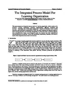
Let us take a closer look at the notion of a process fragment. Figure 1 shows 4 fragments in a process model. Only the blue marked fragments have a single incoming and outgoing connection and can be reused in the pattern. The part of the process model marked in red has two incoming connections (the two output branches of the decision) and two outgoing connections (the two input branches of the merge). If you select two of these connections, for example the lower output branch of the decision and the upper input branch of the merge, you have not selected a proper fragment that can be reused in the pattern. Figure 1. Fragments in a process model
If two connections do not identify a valid selection of a fragment that can be reused in the pattern, an error message tells you to revise your selection of connections.
15
Sample: We show two examples. The first example illustrates the use of business items and business item states in an alternative compound. In this example, we will create the process model shown in Figure 1. The second example illustrates the reuse of a process fragment as an argument in the pattern wizard with two connections selected. Create a new process model and connect the start and terminate events. Then select this connection as is shown next.
Instantiate the pattern as is shown in the next screen capture. You can use the Application business item as defined in the sample modeling project HiringExample.mar that is available with this article series. Note that the fields to specify business items and business item states are synchronized with each other such that their values remain consistent with each other. For example, only when you select No State as the value of the business item input state of the decision, you can specify different business item states on each of the branches. If you want a specific output state of the business item in the merge, then this output state must be provided by the task on each branch.
The resulting process model is shown next.
16
With our second example, we show the reuse of a process fragment. Select the incoming connection of the decision and the outgoing connection of the merge from the alternative compounded that we created in the first example. The connection pair identifies the large blue fragment shown in Figure 1.Then invoke the pattern and insert * as the name of the task in the first branch. Fill in the other fields of the wizard as is shown next. Click Apply Pattern.
The process fragment between the two selected connections is reused on the upper branch of the pattern as is shown next.
Related Patterns: To add more tasks or subprocesses to a branch of the pattern, apply the Insert Task, Insert Process or Sequence patterns to a connection on this branch. To model a process where control can flow from one branch to another before the two branches are merged, apply the Alternative Branch pattern. To merge several gateways into a single gateway, use the Merge Elements refactoring. For refactorings, see Part 4 of this article series.
17
Parallel Compound Pattern Name: Parallel Compound. Intent: Use this pattern to add a flow of several parallel branches to your process model that begins with a fork and ends with a join. Also Known As: The Parallel Compound pattern is a combination of the Parallel Split and the Synchronization workflow patterns (see Russell et al. in Resources below) that enclose several parallel branches. The pattern implements the parallel routing and rendezvous of flows. Structure: The parallel compound pattern can be invoked by selecting one connection or a pair of connections. A wizard opens as is shown next.
18
Information about the input business item and business item state of the fork that starts the pattern and about the output business item and business item state of the join that ends the pattern can be entered in the wizard. Recall that a fork or join can have a user-defined name in WebSphere Business Modeler, but these names are not visible in the diagram and are therefore not editable in the wizard. The name of one task can be specified for each parallel branch. The input and output business items and business item states are inherited from the information provided for the fork and join and are therefore not editable for the task. To add or remove additional branches to/from the list, click right and select Add or Remove from the context menu. Consequences: When the pattern is applied without entering any information in the wizard, the selected connection is refined with the following process fragment.
No empty branch can be created in this pattern because all parallel branches are always executed and executing an empty branch is not meaningful. This means, when a dash “-” is provided as the name of the task in a branch, the dash will be interpreted as the task’s name by this pattern, in contrast to the Alternative Compound pattern where the dash indicates an empty branch. Sample: We show an example where we recreate a part of the Evaluate Candidate process from Part 1 of this article series, but this time we also model business items and business item states. Create an initial part of this process and select the connection between the Check CV task and the terminate event as is shown next.
Invoke the Parallel Compound pattern. Instantiate it as is shown next by creating three branches containing the tasks Review Selected Publications, Examine Publication Profile, Check Grades & Certificates. Recall that you need to add a new branch first before you can enter the third task name. Select the Application business item as input and output of the compound. Select Received as its input state and Closed as its output state. You can 19
use the Application business item as defined in the sample modeling project HiringExample.mar that is available with this article series. Click Apply Pattern.
The pattern instantiated with data flow is added to your process model. The Application business item is added to the Check CV task as its output to properly connect the required input for the fork.
As in the case of the Alternative Compound pattern, you can select two connections to reuse a process fragment on one branch of the Parallel Compound pattern. See the description of the Alternative Compound pattern for further information. Related Patterns: To add more tasks or subprocesses to a branch of the pattern, apply the Insert Task, Insert Process or Sequence patterns. To add additional parallel branches to the pattern or to add additional parallel connections between existing branches, select two connections and apply the Parallel Branch pattern (see this article). Merge multiple forks and joins using the Merge Elements refactoring (see Part 4 of this article series).
Loop
20
Pattern Name: Loop. Intent: The Loop pattern allows you to add a cycle to your process model that begins with a merge, comprises a sequence of loop tasks, and ends with a decision. On the backward connection from the decision to the merge, so-called rework tasks can be added that are executed before the loop body is entered again. Also Known As: The Loop pattern allows users to add structured loops (iterations, cycles) in the form of a while … do (pre-test) or a repeat … until/do … while (post-test) loop to the model. It corresponds to the Structured Loop workflow pattern (see Russell et al. in Resources below). Syntactically, it is a combination of the Simple Merge followed by the Exclusive Choice workflow patterns. Structure: The Loop pattern can be invoked by selecting one connection or a pair of connections. A wizard opens as is shown next.
The wizard contains three tabs named Loop Parameters, Loop Body Tasks, and Rework Tasks.
21
In the Loop Parameters tab, information about the input business item and business item state for the merge, the output business item and business item state for the decision as well as the decision name can be entered. Furthermore, the names and probabilities of the exit branch that leaves the decision and the loop branch connecting the decision back to the merge can be specified. Note that the business item and business item state fields of the branches are synchronized with the corresponding fields for the merge and decision gateways. For example, the output business item state of the decision is the same as the business item state of the exit branch. The business item state entered for the loop branch is the same as the business item state in the first row of the Rework Tasks tab. The business item and business item state of the last rework task are the same as the input business item and business item state of the merge. In the Loop Body Tasks tab that is shown next, information about the tasks between the merge and the decision in the loop body can be entered. The first row shows the merge from which the loop body starts. The output business item and business item state for the merge can be edited. In the subsequent rows, more tasks with their output business items and business item states can be added. To add or remove additional tasks to/from the list, click right and select Add or Remove from the context menu.
In the Rework Tasks tab that is shown next, tasks can be added for the backward connection, i.e., the loop branch that leads back from the decision to the merge. In the first row, the name of the loop output branch of the decision is shown. In the subsequent rows, more tasks with their output business items and business item states can be added. To add or remove additional tasks to/from the list, click right and select Add or Remove from the context menu.
Consequences: When the pattern is applied without entering any information in the wizard, the selected connection is refined with the following process fragment.
22
The merge and decision are added to the model. Between them, a default task with name Body Task name is placed. The two branches of the decision are named Exit Branch and Loop Branch. The exit branch connects to the originally selected connection, while the Loop Branch connects back to the merge. On the loop branch, a default rework task with name Rework Task Name is placed. The outcome of the decision gateway determines whether the loop is repeated. This means, the loop body tasks will be executed at least once. The Rework tasks will only be executed when the decision outcome activates the loop branch and the loop repeats. By leaving the loop body empty without any tasks and placing only rework tasks on the loop branch, a while-do (pre-loop test) loop is defined because all rework tasks are only executed when the decision outcome activates the loop branch. When leaving the loop branch empty without any tasks and placing only tasks on the loop body between the merge and the decision, a do-while (post-loop test) loop is defined. Loops created with the loop pattern are always properly nested within each other. When using this pattern, you cannot create unstructured cycles with overlapping connections. Sample: We show an example illustrating the use of business items and business item states. In this example, we create the initial part of the Approve Hire and Issue Contract process that you worked on in Part 1 of this article series, but refine it with data flow. Create a small process model consisting of a start event, followed by the Issue Contract task, and ending in a terminate event as is shown next.
Select the connection between the start event and the Issue Contract task. Invoke the loop pattern. Fill in the Loop Parameters tab as is shown next. This means, enter Data Complete and Accurate? as the name of the decision. Select the Application business item as input of the merge and output of the decision. The business item input state is Accepted, its output state is ApprovedForContract. Name the exit branch Yes and the loop branch No. Enter a 70 % probability that the exit branch is taken and a 30 % probability that the loop branch must be taken. Select IncompleteForContract as the business item state for the loop branch. The state for the exit branch is already set from the output business item state of the decision. 23
Now fill in the Loop Body Tasks tab as is shown next. Enter the task name Review Employee Data in the second row, select the Business item Application, but do not select a specific business item state as the Application item can be in two different states after the review. The business item state field for the merge can show the value Accepted at this stage, but when you fill in the Rework Tasks tab as described next, it will be synchronized to show the value No State. Note that ‘No State’ in WebSphere Business Modeler indicates ‘any state’ – a business item is always in some state, but it can for example be in one of several possible output states after a task has been executed. This is for example the case with the Review Employee Data task that sets the state of the Application to either IncompleteForContract or ApprovedForContract as we can see from the business item states of the loop and exit branches.
Now fill in the Rework Tasks tab as is shown next. Enter the task name Return to Submitting Manager in the second row, select the Business item Application, and specify IncompleteForContract as its state. The first row should already show the information that you entered in the Loop Parameters tab for the loop branch.
Click Apply Pattern. The start event is replaced by data flow showing the Application business item entering the process in state Accepted. The decision branches show the two
24
possible outcome states of the Review Employee Data task: ApprovedForContract and IncompleteForContract. For the ApprovedForContract state, the exit branch named Yes is taken and it connects to the Issue Contract task. For the IncompleteForContract state, the loop branch named No is taken and it leads back to the merge. On the loop branch, we can see the Return to Submitting Manager task as the only rework task in this example.
Related Patterns: Use the Sequence or Insert Task/Insert Process patterns to add more loop body or rework tasks and subprocesses to a loop. You can add unstructured cycles to your model by applying the Alternative Branch pattern. See the description of this pattern for more details.
Alternative Branch
and Parallel Branch
Pattern Name: Alternative Branch/Parallel Branch Intent: The alternative and parallel branch patterns allow you to create a new connection that begins in the connection that you select first and ends in the connection that you select second. At the beginning and end of the new connection, either a decision and a merge gateway in the case of the Alternative Branch pattern or a fork and a join gateway in the case of the Parallel Branch pattern are added. The patterns make it possible to create processes with very flexible branching flows, which go beyond the block-like structures that can be created with the Sequence, Compound, and Loop patterns. The Alternative Branch pattern in addition allows you to add unstructured cycles to your model. Figures 2 and 3 illustrate process models that can be created when using the Branch patterns. Figure 2. Process model with unstructured alternative branches including a cycle.
25
The process model in Figure 2 contains 3 merges and 3 decisions, but these merges and decisions are not placed in well-structured blocks such that one decision would always be exactly matched by a merge. We call such a flow unstructured. The process model also contains a cycle involving merges M1 and M2 and decision D3.The two merges M1 and M2 specify two possible entries into the cycle. Figure 3. Cycle-free process model with unstructured parallel branches.
The process model in Figure 3 shows an unstructured model with parallel flows starting and ending in different forks and joins. For example, join J2 synchronizes two branches that are opened by fork F1 and fork F2. Note that a process fragment with forks and joins must never contain a cycle, i.e., a backward connection leading back to a join. A cycle or loop that begins in a join will always have a deadlock as the join waits for input from all branches before it can execute, but the loop branch can only provide input after the fork has executed. This is an impossible situation called a deadlock. The control-flow analysis contained in this release of the accelerators allows you to automatically detect deadlocks and other types of control-flow errors. See Part 1 of this article series for details. Also Known As: The Alternative Branch pattern is a combination of the Exclusive Choice followed by the Simple Merge workflow patterns (see Russell et al. in Resources below).When used to create backward connections, it enables users to add the Arbitrary Cycles pattern to their process models. The Parallel Branch pattern is a combination of the Parallel Split followed by the Synchronization workflow patterns (see Russell et al. in Resources below).
26
Structure: The patterns do not have a wizard. To create unstructured models, select two connections by holding the SHIFT key pressed. Click first on the connection where the branch should begin and click second on the connection where the branch should end. Consequences: In order to create a correct model, you must only use one type of branch in a fragment of your model. If you mix both types within a fragment, your model will always contain control-flow errors. We have guarded the application of both branch patterns in the accelerators to prevent you from applying a branch incorrectly. You will see the following error messages when trying to apply the Alternative Branch pattern to a fragment that contains a fork or join gateway:
A parallel branch may only be added to process fragments that do not contain a decision or merge gateway:
Furthermore, a process fragment with forks and joins must never contain a cycle, i.e., a backward connection leading back to a join. The pattern prevents you from adding a cycle to your model when applying the Parallel Branch pattern. The following error message is displayed:
27
Sample: In our first example, we look at the most common use case for the Alternative Branch pattern, namely the creation of a cyclic process by adding a backward connection to the model. Create a process model that contains the Review Employee Data and Issue Contract tasks in a sequence as is shown next.
Now hold the SHIFT key pressed and select first the connection between the two tasks, followed by the connection between the start event and the Review Employee Data task. Note the two different markings of the selected connections in the next screen capture that distinguish the order of selection.
Apply the Alternative Branch pattern. A cycle will be added around the Review Employee Data task, i.e., this task becomes part of the loop body that you just created. To add rework tasks to this loop, select the backward connection, i.e., the loop branch leaving the decision and apply the Sequence pattern for example.
28
In our second example, we discuss a use case where an additional connection between two alternative branches must be added. Take a look at the model of a mortgage approval process with two alternative branches that is shown next.
If the customer is not creditworthy, a rejection is sent by the bank and the application of the customer is closed. If the customer is creditworthy, a mortgage offer is sent, the documents are completed, and an account is set up for paying out the mortgage. We notice that the process model assumes that the customer accepts the offered mortgage. This may not always be the case. If the offer is rejected by the customer, the bank employee should contact the customer to find out why and then also close the application. To achieve this change in the process model, hold the SHIFT key pressed and select first the connection between the Send Mortgage… and Complete Documents tasks in the Yes branch of the decision and then the connection between the Send Rejection and Close Application tasks in the No branch of the decision.
Invoke the Alternative Branch pattern. A new connection connects the two branches that is guarded by new decision and merge gateways.
Place the Contact Customer task on this connection by invoking the Insert Task pattern. Change the description of the decision to Customer Accepts?. The result is a process model where the customer is contacted when he does not accept the offer.
29
We could apply the Alternative Branch pattern again to allow the bank to revise its offer after it has contacted the customer by adding a backward connection from the output of the Contact Customer task to the input of the Send Mortgage …. task. In our third example, we look at a use case for the Parallel Branch pattern. Our example describes the activities of a user when ordering products in an online shop. We would like to modify this process such that the user must additionally read warranty conditions and accept the payment and warranty conditions once he has read both. In parallel, he can read the product information. To achieve this change, we select the incoming connection of the Read Product Information task first, followed by the outgoing connection of the Read Payment Conditions task as is shown next.
A new parallel branch is now added to the model as is shown below.
Add the Read Warranty Conditions task to this branch and add the Accept Conditions task to the connection leaving the join added by the pattern to complete the intended change of the process model as is shown next.
30
Related Patterns: To add additional tasks and subprocesses to the created branches, use the Insert Task, Insert Process, and Sequence patterns. To improve the layout of the resulting process model, it may be necessary to reorder the branches entering or leaving a gateway. The Automatically Order Branches refactoring can automate this for you. To combine gateways that connect directly to each other into a singe gateway, apply the Merge Elements transformation. See Parts 3 and 4 of this article series for more details on transformations and refactorings.
Configuration of the Accelerators Palette The Accelerators palette is a configurable Eclipse view that provides you with an easy access to the available patterns, transformations, and refactorings. You can place it anywhere on your screen and customize it to your needs. To open the Accelerators palette, select Window>Show View>Other...in WebSphere Business Modeler. Then scroll down to Business Modeler Views, select Accelerators Palette and click OK.
The palette will install as a new view at the bottom of WebSphere Business Modeler. You should need to install the palette only once and it should be available for you the next time when you open WebSphere Business Modeler on the same workspace.
31
However, when you switch between the 4-pane, 2-pane and 1-pane layouts in WebSphere Business Modeler, the palette will close and you must reopen it. Click on an icon in the palette to invoke a pattern, transformation, or refactoring. Hover with your mouse over an icon to see a short description of it. Click right on the grey tab of the Accelerators palette view and select Detached as is shown next.
You can now move the palette to any position on your screen. You can also resize the palette as any other window. We found it convenient to add the palette to the lower left pane in WebSphere Business Modeler as is shown next.
The Accelerators palette by default shows all icons of all patterns, transformations and refactorings. However, you can also select your subset of accelerators and arrange them in groups with names of your choice. 32
For this purpose, invoke Window > Preferences in WebSphere Business Modeler. In the Preferences view that opens, select the Accelerators Palette as is shown next.
The Selected Operations view lists all operations, i.e., patterns, transformations, and refactorings that are currently shown in the Accelerators palette. The Available Operations view shows you any remaining operations that are not yet shown in the palette. By default all available operations are selected for the palette and the Available Operations view is empty. You can perform the following configuration operations: • • • •
Define and add your own groups by entering a group name in the text box below the Selected Operations view and pressing the Group button. The new group is added to the Selected Operations view. Rename a group by double-clicking and editing a group name in the Selected Operations view. Remove a group by selecting the group in the Selected Operations view and then click on the Remove button. The group will disappear and its operations will be listed in the Available Operations view. Add an operation to a group by first selecting the group in the Selected Operations view, then select the operation in the Available Operations view and then click the
33
• • •
Add button. The operation will disappear from the Available Operations view and be added to the selected group. You do not need to expand the + sign in front of the group to add an operation. Remove an operation from a group by expanding the + sign in front of the group, then select the operation and click the Remove button. The operation will disappear from the group and be added to the Available Operations view. Move an operation from one group to another by dragging and dropping the operation within the Selected Operations view. Change the order of operations within a group by dragging and dropping the operation within the group expanded in the Selected Operations view.
An operation can only be selected for one group at a time. To return to the initial default setup of the palette, click on Restore Defaults. When adding or removing operations to or from a group using the Add or Remove button, multiple operations can be selected in the views by holding SHIFT or CTRL pressed. In the screen capture that is shown next, we configured the Accelerators palette such that it only shows the 8 available patterns.
To achieve the configuration, delete all groups except the Patterns group. Reorder any patterns within the Patterns group by dragging and dropping them within the group as you like. Then click Apply and OK. Your changes should be immediately visible in the palette. If a configuration change is not visible in the palette, close and re-open the palette for the view to refresh, i.e., select Window>Show View>Other... in WebSphere Business Modeler. Then scroll down to Business Modeler Views, select Accelerators Palette and click OK. A palette configuration is valid with respect to a workspace. This means, for each workspace you can have a different configuration, but it also requires that you
34
configure your palette each time you switch to a new workspace if you want to deviate from its default configuration.
Summary In this article we introduce you to the patterns that are available in release 2.0 of the IBM Pattern-based Process Model Accelerators for WebSphere Business Modeler. The patterns enable you to add common and widely used control- and data-flow structures such as parallel and alternative branches or loops to your model in a simple, fast and correct manner. Sample scenarios illustrate the use of the patterns and explain in detail how patterns are instantiated with business items and business item states. This article also describes how to configure the Accelerators palette.
Resources
IBM Pattern-based Process Model Accelerators for WebSphere Business Modeler Part 1: Understand Process Patterns and Quality & Change Management during Process Modeling, IBM DeveloperWorks, forthcoming 2009. See here.
IBM Pattern-based Process Model Accelerators for WebSphere Business Modeler Part 3: Master Process Model Change with Ready-to-Use Transformations, IBM DeveloperWorks, forthcoming 2009. See here.
IBM Pattern-based Process Model Accelerators for WebSphere Business Modeler Part 4: Improve Process Models through Refactoring, IBM DeveloperWorks, forthcoming 2009. See here.
N. Russell, A.H.M. ter Hofstede, W.M.P van der Aalst, and N. Mulyar: Workflow Control-Flow Pattern Library: A revised View. BPM Center Report BPM-6-22, BPMcenter.org, 2006. See also www.workflowpatterns.com.
F. Buschmann, R. Meunier, H. Rohnert, P. Sommerlad, M. Stal: Pattern-Oriented Software Architecture – A System of Patterns, Wiley 1996.
E. Gamma, R. Helm, R. Johnson, J. Vlissides: Design Patterns: Elements of Reusable Object-Oriented Software, Addison-Wesley 1995.
Tutorials and Samples for WebSphere Business Modeler Version 6.2: Learn about business process modeling with WebSphere Business Modeler V6.2 and download additional example models.
WebSphere Business Process Management V6.2 Information Center: Access more information about Business Process Management with WebSphere V6.2.
35
•
T. Gschwind, J. Koehler, J. Wong: Applying Patterns during Business Process Modeling. Proceedings of the 6th Intern. Conference on Business Process Management, LNCS 5240, pages 4-19, Springer 2008.
•
R. Kong: Modeling business processes in WebSphere Business Modeler for BPEL transformation, IBM developerWorks, January 2008.
•
J. Koehler, J. Vanhatalo: Process anti-patterns: How to avoid the common traps of business process modeling, Part 1: Modeling Control Flow, IBM developerWorks, February 2007.
•
J. Koehler, J. Vanhatalo: Process anti-patterns: How to avoid the common traps of business process modeling, Part 2: Modeling Data Flow, IBM developerWorks, April 2007.
36
IBM Pattern-based Process Model Accelerators for WebSphere Business Modeler Part 3: Master Process Model Change with Ready-to-Use Transformations Level: Intermediate Thomas Gschwind (
[email protected]), Research Staff Member, IBM Jana Koehler (
[email protected]), Research Staff Manager, IBM Janette Wong (
[email protected]), Senior Technical Staff Member, IBM Cedric Favre (
[email protected]), Pre-Doctoral Researcher, IBM Wolfgang Kleinoeder (
[email protected]), Research Emeritus, IBM Alexander Maystrenko (
[email protected]), Pre-Doctoral Researcher, IBM Krenar Muhidini, Student, Jacobs University Bremen, Germany This article series walks you through the IBM Pattern-based Process Model Accelerators V2.0 for WebSphere Business Modeler, a set of plug-ins for IBM WebSphere Business Modeler that add patterns, transformations, and refactorings to your business process modeling environment. In Part 3 of this article series we discuss transformations that apply a complex change to a process model encapsulated in a single click.
Introduction This article is Part 3 of a series of 4 articles introducing IBM Pattern-based Process Model Accelerators V2.0 for WebSphere Business Modeler. The accelerators, as we will call them from now on, provide you with a set of plug-ins for IBM WebSphere Business Modeler that add patterns, transformations and refactorings to your business process modeling environment. In addition, a feature to automatically detect control-flow errors is at your disposal. By using the accelerators you move away from a traditional business process modeling approach where process models are drawn by dragging and dropping elements on the drawing canvas that are then manually connected. The accelerators enable you to create business process models of higher quality by composing them from larger building blocks or by applying semantically correct change operations to your entire model with a single click. Your models will contain significantly less modeling errors, modeling becomes a much more fun exercise and you will experience productivity gains of about 70 % compared to the traditional approach. In this article, we discuss the transformations that are contained in this release of the accelerators. A transformation is a complex change to a business process model that you can apply with a single click. You can understand it as a macro-editing operation that
1
contains a sequence of several editing steps that add, delete, or modify elements in your process model. The following transformations are available in this release of the accelerators: 1. Duplicate Element 2. Merge Elements 3. Replace Global Process … 4. Remove Region 5. Associate Data … 6. Autolink Elements 7. Toggle Gateways 8. Reorder Sequence 9. Convert to Alternative Compound 10. Convert to Sequence
Prerequisites This article is Part 3 of an article series and we assume that you are familiar with Part 1 of this article series. This means, • •
you have IBM WebSphere Business Modeler V6.2.0.1 with Fixpack 1 installed and you installed the accelerators and worked through the example modeling project HiringExample.mar
We also assume that you have basic knowledge of WebSphere Business Modeler, i.e., that you are familiar with the product and you have gained some modeling experience while creating business process models. You should also be familiar with the basic model elements such as gateways, tasks, subprocesses, start and terminate events from the Business Process Modeling Notation (BPMN) as available in WebSphere Business Modeler. The help available in WebSphere Business Modeler provides you with the necessary background. Part 1 of this article series gave you detailed information on where to download the accelerators and how to install them as well as how to validate your installation. Part 1 also introduced you to 5 of the available transformations: Autolink Elements, Convert to
2
Alternative Compound, Merge Elements, Associate Data, and Toggle Gateways. In addition, it introduced you to the Control-Flow Analysis that allows you to easily locate modeling errors in your process model. Part 2 provided you with detailed documentation of the available process patterns and explained how to configure the Accelerators palette.
General Hints on How to Use the Transformations In this article, we describe all available transformations in detail. Following Fowler (see Resources below) and the common guidelines for the description of patterns, we describe a transformation (and a refactoring in Part 4 of this article series) using the following information. Transformation Name: A descriptive name that helps to identify and refer to the transformation. Intent: A description of the goal behind the transformation. Motivation: Reasons for using the transformation and circumstances under which it is not applicable. Mechanics: A concise step-by-step description of how to apply the transformation. As our transformations encode a complex editing operation in a single click, we focus on describing the preconditions, i.e., how to correctly select the model elements to which the transformation is applicable, and the effects, i.e., the change that happens to your model. Sample: An example showing how the transformation works. Related transformations: If applicable, we point you to selected patterns, transformations, and refactorings in this release of the accelerators that are especially useful when being combined with the described transformation. A transformation is usually applied to a selected set of model elements, which can be connections, activities, gateways, and events. When you have nothing selected, a transformation is either applied to your whole model or it is not applied at all depending on what the transformation does. Following your selection of model elements, you have two choices to invoke a transformation: 1. click on the drawing canvas of your business process model diagram and then invoke the transformation at the bottom of the pull-down menu, or 2. click on the corresponding graphical symbol in the Accelerators palette. We explained both choices in Part 1 of this article series. We recommend that you save your model before you apply a transformation. This will make it easier for you to undo unwanted changes by simply discarding a model and
3
reopening it again in its last saved state. Alternatively, you can use the undo function provided by WebSphere Business Modeler. This will undo each of the individual editing operations out of which a transformation is composed in a step-by-step manner.
Duplicate Element Transformation Name: Duplicate Element Intent: Creates a copy of a selected activity that inherits the attributes of the activity and its outgoing connections. Between the selected activity and its copy a new control-flow connection is added. Motivation: Use this transformation to duplicate a selected local or global task, human task, business rules task or service and connect the selected activity with an outgoing connection to its copy. The copy inherits all attributes of the selected activity. Use the transformation when you are refining the activities in your model, i.e., when you want to split the functionality that is encapsulated within one activity of your current model across two activities, but the two new activities will still share a large subset of attributes. Mechanics: Select exactly one activity (local or global task, human task, business rules task, or service), but not a local or global subprocess or loop model element (While-Loop, Do-While Loop and For Loop in WebSphere Business Modeler) and invoke the transformation. A copy of the selected activity is placed on the canvas to the right of the selected activity. All outputs of the selected activity are removed and added to the copy. Only a single control-flow output remains for the selected activity that is connected to the single control-flow input of the copy. Attributes such as for example an associated organization or classifier are inherited by the copy. When you try to apply the transformation to a local subprocess, the following error message is displayed.
Sample: Our first example shows a selected business rules task at the left and the result of applying this transformation to this task on the right.
4
Our second example shows a human task named Review Application with a business item input and two business item outputs. The task is colored by organization unit.
The result of applying the Duplicate Element Transformation to this human task is shown next.
The associated organization unit is inherited by the copy of the task, which is reflected in the coloring. Related transformations: This transformation is similar to the Insert Task pattern, but creates a new activity by reusing the attributes of an existing activity. In contrast to Insert
5
Task that only creates a task, this transformation can create human tasks, business rules, and copies of global processes. The inverse transformation is Merge Elements.
Merge Elements Transformation Name: Merge Elements Intent: Takes two model elements of the same type that are directly connected and merges them into a single element of this type. Motivation: Use this transformation when you want to simplify your model and the intended simplification implies to delete elements, while preserving the existing flow. The transformation is especially useful when you want to simplify branching flows by combining several gateways into a single gateway. Mechanics: The Merge Elements transformation is applicable to pairs of directly connected gateways, local or global tasks, human tasks, business rules tasks, or services, but not to local or global subprocesses and loop model elements. To apply the transformation, you must select exactly two elements of exactly the same type and these elements must have a direct connection. The transformation deletes the second element in the flow and reconnects all its outgoing connections by modifying the outputs of the first element. When you select elements of different types, elements to which the transformation is not applicable, elements that are not directly connected, or more than two elements, the following error message is displayed.
Sample: Our first example reverses the effect of the Duplicate Element transformation that that we discussed in the sample of the Duplicate Element transformation. Select the two human tasks as is shown next.
6
Then invoke Merge Elements. The two human tasks are recombined by deleting the second task and adding any outputs of it to the first task as is shown next.
Our second sample illustrates the effect of the transformation on decision gateways. When merging two connected decisions as is shown next, the second decision is removed, but its branches are combined with the branch of the first decision.
7
In this example, the Interview? and How? decisions are selected for applying the Merge Elements transformation. The result is shown next. The branch names and conditions are combined by “and”. The name of the first decision is preserved.
Note that any expressions that were defined for a branch are removed by the transformation, because they are not valid in the context of the combined gateway. We recommend that you verify the output conditions and their percentages after you applied the transformation to decision gateways, because the transformation cannot imply your intended decision logic. Related transformations: The inverse transformation is Duplicate Element, but this transformation is only applicable to activities, not to gateways.
Replace Global Process … Transformation Name: Replace Global Process Intent: Replaces a selected global process by another global process chosen by the user from the processes that are available in the current modeling project or its reference group. Motivation: Reusing processes across several models is a common practice. When changing a process model A that is reused in a process model B, it can happen that a change in A makes its reuse in B obsolete, requiring to replace A by some other process C in model B. The Replace Global Process transformation allows you to perform such replacements easily. Mechanics: Select a global process and invoke the transformation. A window will open that allows you to browse to the available process models in your workspace as is shown next.
8
Select a process from the list and click OK. The selected process will replace the process in the diagram and it will be connected to the existing flow by adding any missing inputs or outputs to the process. This modification of the inputs and outputs can make the occurrence of the global process in the current process model inconsistent with the global process definition in the workspace. This inconsistency is shown in the Errors View when saving the transformed model. We discuss in the samples section how to address such an inconsistency. If you want to avoid any inconsistencies, only replace processes with each other that have exactly the same inputs and outputs. Sample: In our example, we discuss what happens if a global process is replaced by another global process that does not have all inputs and outputs defined to re-establish the existing connections in the process model. The process model that is shown next reuses a Verify Goods process that has a Bill, an Order, and a Package business item as inputs and outputs. Our goal is to replace the Verify Goods process by a simpler Verify Bill process that has only the Bill business item as input and output.
9
The transformation adds the missing Order and Package business items to the Verify Bill process to reconnect it to the existing flow in the model. When saving the transformed model, an error is displayed that the process invocation of Verify Bill is no longer consistent with its global process definition.
You have two choices to address this error: 1. You can modify the global process definition of Verify Bill and add the required inputs and outputs. This will affect other process models that use this process, because you adjust a global process definition to the local requirements of one reusing process. 2. You can click on the process invocation of Verify Bill in the diagram and select Update Global Element from the pull-down menu. Then save your model. The error will disappear and only those inputs and outputs remain connected that the global process definition provides. With this second option, you adjust your local usage of a process to its global process definition.
You should consider how any dangling inputs and outputs of a reused process are handled by your process model. In this example, the Ship Goods task cannot execute as it does not receive the required Order and Package inputs anymore. In the screen capture below, we have decided that these inputs are directly provided by the Provide Goods task.
Related transformations: none in this release.
10
Remove Region Transformation Name: Remove Region Intent: Cuts out an entire connected region containing an arbitrary selection of connected model elements and reconnects the remaining flow. Motivation: Use this transformation when parts of your model are no longer valid and you want to discard them, but you would like to be supported in reconnecting the remaining flow in the model. The transformation behaves like a smarter delete that removes elements from the model, but is capable of reconnecting the remaining ones. Mechanics: Select an arbitrary, but connected region of your model by clicking on model elements or pulling your mouse over a part of the diagram holding the left mouse button pressed. When you release the mouse button, all model elements in this part of your model will be selected. Then invoke the transformation. It deletes all selected elements and tries to reconnect the remaining flow, i.e., it connects those connections entering and leaving the region removed by the transformation. The automatic reconnection may not always lead to a correct control flow when the process model contains complicated flow logic involving parallel and alternative flows that are opened by forks and decisions and end in joins and merges. In Figure 1, we illustrate 5 possible situations. Figure 1: Five possible situations for connections crossing the boundaries of a removed region (situation 1 leftmost, situation 5 at the right). a
a
becomes
becomes
becomes
becomes
becomes a
Situation 1: If only a single control-flow input and output connection exist for the selected region, a so-called fragment is removed from the model (see Part 2 of this article series). Removing a fragment always leads to a correctly reconnected flow. Situations 2 and 3: If several control-flow input connections enter the selected region, but only one output connection exist or vice versa, a fork or join is added between the connections to reconnect them. Situation 4 (combines Situations 2 and 3): Several control-flow input and output connections enter the selected region. Input connections are combined with a join, output connections are combined with a fork and the join and fork are connected with each other.
11
Situation 5: A single data-flow connection enters the selected region and a single dataflow connection leaves the selected region and both data-flow connections have the same business item associated. The two connections are reconnected. In case of several dataflow connections that enter or leave the selected region or if different business items are associated with the connections, the model becomes disconnected. The reconnected flow can become incorrect in Situations 2, 3, and 4. For example, when incoming connections are opened by a decision gateway, they are now connected with a join introducing a deadlock into the model. See Part 1 of this article series for a discussion of control-flow errors and how to easily detect such errors using the ControlFlow Analysis provided with this release of the Accelerators. We recommend to run the Control-Flow Analysis whenever a region was removed from the model that had several incoming and outgoing connections. In Situations 2, 3, and 4, the transformation will not always remove all gateways to allow the user to inspect the structure of the control flow that crosses the region borders and make manual changes if desired. We discuss an illustrating example in the Sample section. Sample: In our first example, we select and remove a fragment with a single incoming and outgoing connection as is shown next.
Following Situation 1, the fragment is removed and the two connections are merged into a single one as is shown next.
12
In our second example, we select a region of two tasks that are located on two separate flows, which are not connected to each other.
The two tasks are removed, but the gateways remain in the flow connecting the empty branches with each other.
To remove both gateways, they must be both selected. This selection determines a fragment with a single incoming and a single outgoing connection, which is removed by the transformation. The next screen capture shows what happens if only the merge gateway is selected. This selection determines a region with two incoming connections and one outgoing connection that is not a fragment. Situation 2 applies and a join is added to the model to reconnect the two incoming connections with the single outgoing connection. A deadlock is introduced into the model that must be manually resolved by for example applying the Toggle Gateways transformation to the join gateway, which changes it to a correct merge.
13
Related transformations: Apply the Control-Flow Analysis to validate your process model when a region with more than one incoming or outgoing connection was removed (see Part 1 of this article series for details on how to use the Control-Flow Analysis). Use the Toggle Gateways transformation to change any forks or joins to decisions and merges in case of a detected control-flow error. See the description of this transformation in this article for further details.
Associate Data … Transformation Name: Associate Data Intent: Assigns a new business item to selected connections or to all connections in a process model or removes an existing business item. Motivation: Use this transformation when you want to change control-flow into dataflow and vice versa or if you want to modify existing data flow. Mechanics: Select an arbitrary region of your process model or specific connections and invoke the transformation. A window will open that allows you to browse the business items that are available in your modeling project.
14
Click one of the radio buttons to select either no type, a basic type, or a complex type and select one of the available business items. Then click OK. If you select no type, all business items that are associated with the selected connections will be removed leaving only control flow in the selected region of your model. If you select a basic or complex type, the selected business item will be associated with the selected connections changing or adding data flow in your process model. The types of inputs and outputs of tasks or gateways involved in the selected connections are modified accordingly. If no model element or connection is selected, the transformation is applied to the entire model. If control flow is changed to data flow on connections that include start and end or terminate events, the transformation adds an input and output for the associated business item to the process model. It reconnects the flow to this input and output and the events are removed from the model. If data flow is changed to control flow, a new start and terminate event is added to the model. The data inputs and outputs of the process model are not removed in order to preserve the existing process interface. When associating data with connections that involve global processes, the interface of the global process is modified. This can lead to inconsistencies that are reported in the Errors view when saving the model. See the sample provided with the Replace Global Process transformation on how to address and resolve such inconsistencies. Note that you cannot use this transformation to change the data flow in and out of repositories as this flow should remain consistent with the type of the business item associated with the repository. Sample: The example shows an application of the transformation to an entire process model with no elements selected. The Application business item is chosen as the parameter of the transformation. It is applied to all connections in the example model except the one connecting to the repository.
Note that the start event is removed and that the Application business item becomes an input of the process.
15
Related transformations: none in this release.
Autolink Elements Transformation Name: Autolink Elements Intent: Automatically connects model elements that are placed on the canvas following simple layout guidelines. Motivation: Tired of manually clicking on inputs and outputs and drawing a connection between them? Place activities on the canvas following simple layout guidelines and let the Autolink Elements transformation connect these elements for you and even insert the right gateways between them. Mechanics: The transformation can be applied to both unconnected and partially connected models to quickly create complex business processes. If no model elements are selected, the transformation will try to connect all model elements on the canvas, otherwise, it only connects the selected elements. The following simple rules are applied by the transformation: • • •
If tasks are to be connected in a sequence, they should be placed close to each other in an approximate row. If tasks are to be connected such that they occur on different branches of a decision, then they should be placed in an approximate column. A gateway is added to the model when there is sufficient space between a row and a column of tasks.
The transformation can result in a partially connected model when the transformation cannot clearly determine which layout rules apply to the model elements. Sample: The example illustrates the layout rules. Note that the start event, the Receive Order task, the Ship Order task and the terminate event are placed in an approximate row. Between the Receive Order task and the Ship Order task, three more tasks are placed in an approximate column. Note that we left sufficient space between the Receive Order task on the left and this column of tasks and the Ship Order task on the right such that a gateway fits between them.
16
Invoking the Autolink Elements transformation with no model elements selected followed by applying the Auto-Layout leads to the process model as is shown next. A decision and merge gateway are added to the model such that the tasks in the column are placed on three branches that are connected by these gateways. All model elements are connected.
By default, the transformation will only add decision and merge gateways to create alternative branches. It cannot know whether the user wants to create alternative or parallel flow. Use the Toggle Gateways transformation described later in this article to change decision and merge gateways to forks and joins. Our next example explains how to apply the Autolink Elements transformation to partially connected models. We reuse the first example, but remove its start and terminate events as is shown next.
Now we place a task Approve Order above the existing column of tasks. Our goal is to add another branch to the existing decision and merge. Select this new task and both gateways as is shown next and invoke the Autolink Elements transformation.
17
A fourth branch is added to the decision and merge gateways. Note that selecting the gateways is critical for the transformation to correctly connect the new task. More than one task can be placed on a single branch by arranging several tasks on a row.
Our next goal is to place this entire process fragment on a branch within another decision. Add the tasks Create Order, Suspend Order, and Print Order Information on the canvas as is shown next.
18
Then invoke the transformation again with no model elements selected. A new decision and merge gateway are added.
Note that a gateway is only added if there is at least a single task placed before or after a column of tasks. This means, in our example the Create Order and Print Order Information tasks are essential – they are placed before and after a column of tasks made up of the Suspend Order task and the fragment delimited by the Receive Order and Ship Order tasks. The Autolink Elements transformation therefore recognizes the new branch that is intended for the Suspend Order task and the need to connect this new branch with a newly introduced decision and merge. Related transformations: The Toggle Gateways transformation described next is very useful to change a decision to a fork and a join to a merge and vice versa. To place more activities on a created connection, use the Insert Task, Insert Process or Sequence pattern. To add data flow to your model, use the Associate Data transformation.
Toggle Gateways Transformation Name: Toggle Gateways Intent: Toggles a selected gateway, i.e., converts a fork to a decision and vice versa and converts a join to a merge and vice versa. Motivation: Use this transformation to convert parallel branches into alternative branches and vice versa. Use it also to correct modeling errors that are caused by incorrectly paired gateways, for example, to change an incorrect decision/join pair to a correct decision/merge pair. Mechanics: To apply the transformation, select a single gateway that you want to toggle. The transformation is applied to this gateway and to all correctly matching gateways. This means, when you apply the transformation to a merge that pairs with a decision, the decision and the merge will be changed to a fork and join. To detect matching pairs (or more generally matching sets of parallel and alternative gateways), the transformation analyses the structure of the process model and toggles all those gateways that must be toggled for the control flow to remain correct. When a control-flow error exists in the model involving the selected gateway (see Part 1 of this article series), only the selected gateway is toggled helping the user to change incorrect gateways.
19
When no gateway is selected, the transformation is applied to the whole model if no control-flow errors are detected. Otherwise, no toggling of gateways takes place. Sample: The first example illustrates the toggling of matching gateways in a correct process model. We start from a part of the Evaluate Candidate process that we used in Part 1 of this article series as is shown next. In this part of the process, two decisions are paired with a single merge.
Select the merge gateway and invoke the Toggle Gateways transformation. The merge and both decisions will be toggled in order to preserve the correctness of the process model as is shown next. The three alternative branches are converted into corresponding parallel branches. Toggling only the merge would have introduced a deadlock into the process model.
The second example illustrates the behavior of the Toggle Gateways transformation on a model with a control-flow error. In this example, two forks are incorrectly paired with a closing merge, which leads to a process model with a lack of synchronization error. Select the merge as is shown next.
20
Invoke the Toggle Gateways transformation. Only the merge is toggled to a join correcting the error in the model as is shown next.
Our third example illustrates that the Toggle Gateways transformation does only affect matching gateways in a model. For this purpose, we embed the previous example into a decision/merge pair and select the second fork as is shown next.
Now invoke the Toggle Gateways transformation. It only toggles the matching forks and their join, but leaves the outermost decision and merge unchanged as is shown next.
21
Similarly, when toggling the first Decision named Evaluate Candidate only its matching merge (the right most in the next screen capture) would be toggled.
Related transformations: The Activity to Gateway Form transformation can be applied to transform multiple incoming and outgoing connections of an activity to the corresponding gateway structure, which would then allow you to toggle this gateway. The Merge Elements transformation is useful in combining several gateways into a single gateway. To add missing closing gateways to a model, use the Merge or Join Process Ends and the Close Branches refactorings (see Part 4 of this article series).
Reorder Sequence Transformation Name: Reorder Sequence Intent: Reorders selected activities in a sequence based on a new order that is provided by the user clicking on the model elements. Motivation: Reordering the steps in a process model is a commonly occurring change. Either the order of activities that are already in sequence must be changed or activities must be moved elsewhere in the process flow. Such a reordering is a very time consuming step requiring the user to manually delete and redraw connections. The Reorder Sequence Transformation facilitates this change. Mechanics: The Reorder Sequence transformation is applicable to all activities, i.e., tasks, local and global processes, business rules tasks, and human tasks, as well as loop model elements. Hold SHIFT pressed and click on the elements in the order you want to create. Invoke the Reorder Sequence transformation on the selected elements. The selected elements will be moved after the first element that you selected and control-flow connections will be created between them. When elements are connected with a single data-flow connection, the associated business items are preserved and any required, but missing inputs and outputs are added to the reordered activities to establish a new
22
connection. The positioning of the model elements on the drawing canvas is not changed. Use the Auto-Layout to properly layout the modified process model. If only a single element is selected or elements to which the transformation is not applicable occur in a selection, the following error message is displayed.
Activities cannot be reordered if they are connected with multiple connections. In this case, the following error message is displayed.
Sample: Our example shows a sequence of model elements of different types that we want to order alphabetically.
To define the new order, hold SHIFT pressed and click in the following order on the model elements: Business Rules Task, Process 2, Subprocess, Task, While Loop. The sequence of clicks determines the new order. Apply the Reorder Sequence transformation – it reconnects the elements in the specified order as is shown next.
23
The positioning of the elements on the canvas is not changed by the transformation. Invoke Auto-Layout from Left to Right to adapt the positioning to the new sequential order.
The second example illustrates a scenario of moving a task to the beginning of an alternative branch. We use the initial part of the Handle Signed Contract process from Part 1 of this article series. After the merge gateway, we added a Confirm Receipt task that we would rather like to move to the beginning of the Yes branch before the Verify Necessary Signatures task. To achieve this change, hold SHIFT pressed and click first on the Yes branch first, then on the Confirm Receipt task as is shown next. Note that you must have the output branch selected, not the connection from the decision gateway to the first model element on the branch.
Invoke the Reorder Sequence transformation. The desired change is applied to the model as is shown next.
24
Applying the Auto-Layout adjusts the layout to the change.
Related transformations: The Convert to Alternative Compound transformation takes a set of selected model elements that occur in a sequence and places them on several alternative branches. The Convert to Sequence transformation removes alternative branches from model and arranges the model elements in a sequence.
Convert to Alternative Compound Transformation Name: Convert to Alternative Compound Intent: Takes a set of model elements that are connected in a sequence and places them on different alternative branches embedded within a decision and a merge gateway. Motivation: An initial version of a business process model is often created by defining a sequential process flow. When later refining the model, one realizes that certain activities should occur on different branches of the flow and that gateways must be added to the model. The transformation allows a user to split sequences of tasks across alternative branches that are automatically added to the model.
25
Mechanics: The Convert to Alternative Compound transformation is applicable to all activities, i.e., tasks, local and global processes, business rules tasks, and human tasks, as well as loop model elements. To apply the transformation, click on the activities in a connected sequence that should begin the new alternative branches in the model. Then invoke the Convert to Alternative Compound transformation. For each selected activity, a new branch is created. The selected activity becomes the first activity of this branch. All activities that follow this selected activity and that have not been selected are also added to this branch. All non-selected tasks that precede the first selected task are moved before the decision gateway. This means, by selecting activities in a sequence the user specifies subsequences for each of the alternative branches. If activities are selected that occur on different alternative or parallel branches, the following error message is displayed.
Sample: In the example process that is shown next, the Review Order and Check if Available tasks have been selected.
As a result, two branches are created. The selected tasks are placed on these branches as the first tasks followed by their successor subprocesses or tasks. The Receive Order task that precedes the first selected task is placed before the decision.
26
Related transformations: The Toggle Gateways transformation can be used to change the created alternative compound to a parallel compound. The Reorder Sequence transformation makes it easy to reposition activities within a newly created branch. Convert to Sequence is the dual transformation that takes a set of selected activities that occur on different alternative branches in a model and orders them in a sequence.
Convert to Sequence Transformation Name: Convert to Sequence Intent: Transforms an alternative or parallel fragment of a process model into a sequence of activities deleting all gateways. Motivation: The Convert to Sequence Transformation removes alternative or parallel branches from a model, but keeps all activities on these branches. The activities are arranged in a new sequence. Such a change occurs for example when the branching structure in a model is obsolete and must be changed completely or when branches have been removed and only a single or a few branches are left that a user wants to turn into a sequence. Doing such a change manually would require the step-by-step deletion of all gateways and the manual reconnection of the affected activities. Mechanics: The user selects a single task or gateway. The selected model element determines a fragment that encloses this element. A fragment is a part of the process model that is connected with one incoming and one outgoing connection to the remaining model (see also Part 2 of this article series). All gateways in this fragment will be removed and the activities contained in the fragment are ordered within a sequence. The sequence is built by joining the individual branches starting from the top-most branch in the diagram and proceeding until the lowest branch is reached. The positioning of the activities on the canvas is not changed by the transformation. Apply the Auto-Layout to improve the layout of the model.
27
When selecting a model element that is not a gateway or an activity, or when selecting more than one model element, the following error message is displayed.
In a complex model, large fragments can contain smaller fragments. When applied to a fragment, the transformation will not affect the structure of any of the contained smaller fragments, i.e., these nested fragments will preserve their gateway structures. The samples section below illustrates this behavior in detail. Sample: The example explains the behavior of the Convert to Sequence transformation on a model with several nested fragments. Figure 2 shows an example model where we highlighted 2 fragments with dashed blue frame.The Fulfil Order task is selected. It is contained within a fragment that begins with a decision and ends with a merge. Within this fragment, we highlighted a smaller fragment that starts with a fork and ends with a join. Figure 2: Fragments in an Example Model.
Invoke the Convert to Sequence transformation with the Fulfil Order task being selected. The decision and merge are removed and the Fulfil Order and Reject Order tasks are placed within a sequence beginning with the Receive Order task. The result is shown next. The inner fragment of this process model is not affected by the transformation, i.e., its fork and join gateways are preserved.
28
If we had selected one of the tasks in the parallel compound, i.e., Check Payment, Order From Stock or Determine Shipping, the fork and join would have been removed and the three tasks would directly follow the Fulfil Order task. The decision and merge gateways of the outer fragment would not be affected. The next screen capture shows the result of the Convert to Sequence transformation with the Check Payment task selected before application of the Auto-Layout.
Related transformations: The Reorder Sequence transformation can be used to change the order of the activities in the sequence that is created by the Convert to Sequence transformation. Additional activities can be added to the sequence by using the Insert Task, Insert Process, or Sequence patterns. To remove any part of the process model, use the Remove Region transformation. Convert to Alternative Compound is the dual transformation that takes a set of model elements that are connected in a sequence and places them on different alternative branches embedded within a decision and a merge gateway. To change an Alternative Compound to a Parallel Compound, use the Toggle Gateways transformation.
Summary In this article we discuss business process model transformations that are available in release 2.0 of the IBM Pattern-based Process Model Accelerators for WebSphere 29
Business Modeler. Each transformation encapsulates a complex change in a single click. For each transformation, we describe its intent and discuss the motivation why it should be used. We explain how to correctly apply a transformation to selected model elements and what effects the transformation has. A sample section provides the reader with several examples that illustrate the power of each transformation. By using transformations and combining them with the patterns and refactorings that we describe in Parts 2 and 4 of this article series, user can master changes in a process model in a more effective and more enjoyable way.
Resources
IBM Pattern-based Process Model Accelerators for WebSphere Business Modeler Part 1: Understand Process Patterns and Quality & Change Management during Process Modeling, IBM DeveloperWorks, forthcoming 2009. See here.
IBM Pattern-based Process Model Accelerators for WebSphere Business Modeler Part 2: Advanced Use of Patterns and Configuration of the Accelerators Palette, IBM DeveloperWorks, forthcoming 2009. See here.
IBM Pattern-based Process Model Accelerators for WebSphere Business Modeler Part 4: Improve Process Models through Refactoring, IBM DeveloperWorks, forthcoming 2009. See here.
N. Russell, A.H.M. ter Hofstede, W.M.P van der Aalst, and N.Mulyar: Workflow Control-Flow Pattern Library: A revised View. BPM Center Report BPM-6-22, BPMcenter.org, 2006. See also www.workflowpatterns.com.
M. Fowler: Refactoring. Improving the Design of Existing Code. Addison-Wesley. 2008.
Tutorials and Samples for WebSphere Business Modeler Version 6.2:Learn about business process modeling with WebSphere Business Modeler V6.2 and download additional example models.
WebSphere Business Process Management V6.2 Information Center: Access more information about Business Process Management with WebSphere V6.2.
T. Gschwind, J. Koehler, J. Wong: Applying Patterns during Business Process Modeling. Proceedings of the 6th Intern. Conference on Business Process Management, LNCS 5240, pages 4-19, Springer 2008.
R. Kong: Modeling business processes in WebSphere Business Modeler for BPEL transformation, IBM developerWorks, January 2008.
30
J. Koehler, J. Vanhatalo: Process anti-patterns: How to avoid the common traps of business process modeling, Part 1: Modeling Control Flow, IBM developerWorks, February 2007.
J. Koehler, J. Vanhatalo: Process anti-patterns: How to avoid the common traps of business process modeling, Part 2: Modeling Data Flow, IBM developerWorks, April 2007.
31
IBM Pattern-based Process Model Accelerators for WebSphere Business Modeler Part 4: Improve Process Models through Refactoring Level: Intermediate Thomas Gschwind (
[email protected]), Research Staff Member, IBM Jana Koehler (
[email protected]), Research Staff Manager, IBM Janette Wong (
[email protected]), Senior Technical Staff Member, IBM Cedric Favre (
[email protected]), Pre-Doctoral Researcher, IBM Wolfgang Kleinoeder (
[email protected]), Research Emeritus, IBM Alexander Maystrenko (
[email protected]), Pre-Doctoral Researcher, IBM Krenar Muhidini, Student, Jacobs University Bremen, Germany This article series walks you through the IBM Pattern-based Process Model Accelerators V2.0 for WebSphere Business Modeler, a set of plug-ins for IBM WebSphere Business Modeler that add patterns, transformations, and refactorings to your business process modeling environment. In Part 4 of this article series we discuss refactorings that apply changes to a process model that do not affect its behavior as it can for example be observed when simulating the process.
Introduction This article is Part 4 of a series of 4 articles introducing IBM Pattern-based Process Model Accelerators for WebSphere Business Modeler. The accelerators, as we will call them from now on, provide you with a set of plug-ins for IBM WebSphere Business Modeler that add patterns, transformations and refactorings to your business process modeling environment. In addition, a feature to automatically detect control-flow errors is at your disposal. By using the accelerators you move away from a traditional business process modeling approach where process models are drawn by dragging and dropping elements on the drawing canvas that are then manually connected. The accelerators enable you to create business process models of higher quality by composing them from larger building blocks or by applying semantically correct change operations to your entire model with a single click. Your models will contain significantly less modeling errors, modeling becomes a much more fun exercise and you will experience productivity gains of about 70 % compared to the traditional approach. In this article, we discuss the refactorings that are contained in this release of the accelerators. Following Fowler (see Resources below), the word refactoring can be used as a noun as well as a verb.
1
Refactoring (noun): A small change made to the internal structure of software to make it easier to understand and cheaper to modify without changing its observable behavior. Refactor (verb): to restructure software by applying a series of refactorings without changing its observable behavior. Business process models captured in tools such as WebSphere Business Modeler are one possible form of software. Very often, the model is directly executable and can for example be used for simulation purposes or as an entry into the software development process during which the process implementation is built. It is therefore natural to think about refactoring techniques for process models. As Fowler summarizes, refactoring is important to improve the quality of software: Refactoring is the process of changing a software system in such a way that it does not alter the external behavior of the code yet improves its internal structure. It is a disciplined way to clean up code that minimizes the chance of introducing bugs. In essence when you refactor, you improve the design of the code after it has been written. With refactoring you can take a bad design, chaos even, and rework it into well-designed code. Each step is simple, even simplistic. Yet the cumulative effect of these small changes can radically improve the design. When business process models are used beyond simple documentation, their quality is an important factor to materialize the benefits of a systematic business process management approach. Therefore, we provide you with a set of refactorings in this release of the accelerators that help you to improve the quality of your process models by applying structural changes to your models. Similar to software (program) refactoring for which modern software development environments offer automated support, our refactorings can be applied to a set of selected model elements with a single click. The refactorings improve a model’s structure, but do not change the behavior of the process model. This means, when executed in a simulation environment, the same traces of executing activities can be observed in the original and the refactored process model provided that the refactorings are applied correctly. Some of the refactorings in this release help you to correctly refactor a process model by automatically analyzing the structure of the model. Other refactorings apply a change with the responsibility of the correct application resting solely with the user. The following refactorings are available in this release of the accelerators: 1. Merge Process Ends 2. Join Process Ends 3. Close Branches
2
4. Automatically Order Branches 5. Activity to Gateway Form 6. Extract Subprocess 7. Inline Subprocess
Prerequisites This article is Part 4 of an article series and we assume that you are familiar with Part 1 of this article series. This means, • •
you have IBM WebSphere Business Modeler V6.2.0.1 with Fixpack 1 installed and you installed the accelerators and worked through the example modeling project HiringExample.mar
We also assume that you have basic knowledge of WebSphere Business Modeler, i.e., that you are familiar with the product and you have gained some modeling experience while creating business process models. You should also be familiar with the basic model elements such as gateways, tasks, subprocesses, start and terminate events from the Business Process Modeling Notation (BPMN) as available in WebSphere Business Modeler. The help available in WebSphere Business Modeler provides you with the necessary background. Part 1 gave you detailed information on where to download the accelerators and how to install them as well as how to validate your installation. Part 1 also introduced you already to three of the available refactorings: Automatically Order Branches, Activity to Gateway Form, and Extract Subprocess. In addition, it introduced you to the ControlFlow Analysis that allows you to easily locate modeling errors in your process model. Part 2 provided you with detailed documentation of the available process patterns and explained how to configure the Accelerators palette. In Part 3, we discussed the available transformations in detail.
General Hints on How to Use the Refactorings A refactoring is usually applied to a selected set of model elements, which can be connections, activities, gateways and events. When you have nothing selected, a refactoring is either applied to your whole model or it is not applied at all depending on what the refactoring does.
3
Following your selection of model elements, you have two choices to invoke a refactoring: 1. click on the drawing canvas of your business process model diagram and then invoke the refactoring at the bottom of the pull-down menu, or 2. click on the corresponding graphical symbol in the Accelerators palette. We explained both choices in Part 1 of this article series. We recommend that you save your model before you apply a refactoring. This will make it easier for you to undo unwanted changes by simply discarding a model and reopening it again in its last saved state. Alternatively, you can use the undo function provided by WebSphere Business Modeler. This will undo each of the individual editing operations out of which a refactoring is composed in a step-by-step manner. Following Fowler (see Resources below) and the common guidelines for the description of patterns, we describe a refactoring (and also a transformation in Part 3 of this article series) using the following information. Refactoring Name: A descriptive name that helps to identify and refer to the refactoring. Intent: A description of the goal behind the refactoring. Motivation: Reasons for using the refactoring and circumstances under which it is not applicable. Mechanics: A concise step-by-step description of how to apply the refactoring. As our refactorings encode a complex editing operation in a single click, we focus on describing the preconditions, i.e., how to correctly select the model elements to which the refactoring is applicable, and the effects, i.e., the change that happens to your model. Sample: An example showing how the refactoring works. Related refactorings: If applicable, we point you to selected patterns, transformations, and refactorings in this release of the accelerators that are especially useful when being combined with the described refactoring.
Merge Process Ends Refactoring Name: Merge Process Ends Intent: Closes multiple process branches that end in an activity or in an end or terminate event by introducing a merge gateway. Motivation: Very often, business process models are drawn that involve several branches where each branch ends with an individual end or terminate event. In the case of an
4
incomplete model, a process branch can simply end with an activity. However, the structure of the model would become much clearer if branches that are opened by a decision would be correctly merged. The need to close branches occurs for example, when a new activity must be added to the process model that is executed after all branches have finished execution. This means, the branches should be merged by connecting them to a merge gateway, then the new activity can be added and connected to a single terminate or end event. Closing branches is also a good modeling practice before exporting a process to an execution environment, e.g., IBM WebSphere Process Server. Mechanics: Hold SHIFT pressed and select at least two activities, end or terminate events that end a branch. Note that the activities must be the last elements in a flow and must not have any outgoing connections. Apply the Merge Process Ends refactoring. A new merge gateway is added to the process model. The incoming connections of the selected end or terminate events are redirected such that they connect to the new merge gateway. A new outgoing connection is added to each selected activity to connect the activity to the new merge gateway. The outgoing connection of the merge gateway is by default connected to a single terminate event. However, if an end event is contained in the set of selected events, the transformation uses an end event instead of a terminate event. If only a single model element is selected or elements are selected to which the refactoring is not applicable, the following error message is displayed.
Sample: The example shows an incomplete process model with three branches that are opened by a decision. The upper two branches end in an end or terminate event. The lower third branch contains a task without an outgoing connection. The two events and the task on the third branch are selected for refactoring as is shown next.
5
The result of applying the Merge Process Ends refactoring is shown next.
A merge is added to close the three branches. A single end event ends the overall process flow, because an end event was contained in the set of selected model elements. Note that the Merge Process Ends refactoring always uses a merge gateway to close the branches. No analysis of the process flow takes place. This means, if branches are opened by a fork, closing them with a merge would introduce a lack of synchronization error into the model (see Part 1 of this article series on how to automatically detect control-flow errors). It is a deliberate design decision that the refactoring gives full control to the user about the choice of gateway to close the branches. Related refactorings: The Merge Process Ends refactoring is complemented by the Join Process Ends refactoring that adds a join to the model instead of a merge. A smart version of both refactorings is Close Branches that automatically determines which gateway(s) must be used to correctly close branches in a process model. To change a gateway, use the Toggle Gateways transformation.
6
Join Process Ends Refactoring Name: Join Process Ends Intent: Closes multiple process branches that end in an activity or in an end or terminate event by introducing a join gateway. Motivation: Same motivation as for the Merge Process Ends refactoring, but for branches that are opened by a fork. Mechanics: Hold SHIFT pressed and select at least two activities, end or terminate events that end a branch. Note that the activities must be the last elements in a flow and must not have any outgoing connections. Apply the Join Process Ends refactoring. A new join gateway is added to the process model. The incoming connections of the selected end and terminate events are redirected such that they connect to the new join gateway. A new outgoing connection is added to each selected activity to connect the activity to the new join gateway. The outgoing connection of the merge gateway is by default connected to a single terminate event. However, if an end event is contained in the set of selected events, the transformation uses an end event instead of a terminate event. If only a single model element is selected or elements are selected to which the refactoring is not applicable, the following error message is displayed.
Sample: The example shows an incomplete process model with three branches that are opened by a fork. The upper two branches end in an end or terminate event. The lower third branch contains a task without an outgoing connection.
7
The result of applying the Join Process Ends refactoring is shown next.
A join is added to close the three branches and a single end event is added to end the overall process flow, because an end event was contained in the set of selected model elements. Note that the Join Process Ends refactoring always uses a join gateway to close the branches. No analysis of the process flow takes place. This means, if branches are opened by a decision, closing them with a join would introduce a deadlock into the model (see Part 1 of this article series on how to automatically detect control-flow errors). It is a deliberate design decision that the refactoring gives full control to the user about the choice of gateway to close the branches. Related refactorings: The Join Process Ends refactoring is complemented by the Merge Process Ends refactoring that adds a merge to the model instead of a join. A smart
8
version of both refactorings is Close Branches that automatically determines which gateway(s) must be used to correctly close branches in a process model. To change a gateway, use the Toggle Gateways transformation.
Close Branches Refactoring Name: Close Branches Intent: Closes multiple process end branches by adding the correct merge and/or join gateway(s). Motivation: The Close Branches refactoring merges or joins branches automatically by determining the correct closing gateways. It relieves the user from the burden to analyze the process flow and find out which gateway(s) must be used to correctly close a set of branches. The Close Branches refactoring is applicable to sets of branches where some branches are opened by a decision, while others are opened by a fork, i.e., it can handle situations in which several different gateways must be added to correctly end the process flow and connect it to a single terminate or end event. Close Branches can achieve this in a single refactoring step, while it would require multiple applications of the Merge and Join Process Ends refactorings to achieve the same change. Mechanics: Hold SHIFT pressed and select the model elements at the end of those branches that you want to close, i.e., activities without outgoing connections or end or terminate events. The Close Branches refactoring will try to close all selected branches by adding the missing merge or join gateways. In case of very complex model fragments or models with control-flow errors, some branches cannot be closed, but each branch will be individually connected to an end event. We recommend that you review the model and check it for control-flow errors using the Control-Flow Analysis provided by the accelerators (see Part 1 of this article series) in the case that not all selected branches are closed. If no errors are found, you can close the remaining branches separately using the Merge/Join Process Ends or Close Branches refactorings. If errors are detected in the model, you should correct these errors before applying any further refactorings. Sample: The example shows a process with several parallel branches that are opened by a fork and several alternative branches that are opened by a decision gateway. All activities at the end of a branch as well as the No branch of the decision are selected as is shown next.
9
The refactoring finds out automatically that the branches that are opened by a decision must be closed using a merge, while the branches that are opened by the fork must be closed using a join. The result of the refactoring is shown next. The newly added merge connects to the newly added join which in turn connects to a single terminate event.
Related refactorings: Join Process Ends and Merge Process Ends are simplified forms of the Close Branches refactoring where the user determines the closing gateway by selecting the refactoring. The Toggle Gateways transformation can be used to change a gateway.
Automatically Order Branches Refactoring Name: Automatically Order Branches
10
Intent: Improve the layout of a process model by changing the order of the incoming or outgoing branches of a gateway. Motivation: WebSphere Business Modeler provides users with very advanced automatic layout capabilities in the Auto-Layout Left to Right feature. When re-positioning activities on the canvas, the order of the incoming and outgoing connections is often adjusted by the tool to improve the layout. However with gateways, the available layout feature can sometimes cause crossing connections in the diagram. The Automatically Order Branches refactoring can often help in such cases when being applied to a single gateway, a set of selected gateways, or the entire diagram. Mechanics: Select a single gateway or several gateways that have cluttered branches. Invoke the Automatically Order Branches refactoring. It will try to improve the layout of the model by reordering the branches of the selected gateways. This will very often, but not always succeed. In any case, the refactoring should not make your layout worse, i.e., if the refactoring estimates that no improvement is possible, it makes no change to the diagram. If no model element is selected, the refactoring is applied to the entire model. If a model element is selected that is not a gateway, the following error message is displayed.
Sample: The example shows a join gateway with crossing incoming branches.
11
Trying to improve the layout by changing the positioning of the gateway on the canvas does not improve the situation. Applying the Auto-Layout makes the situation even worse by adding clutter to the outgoing connections of the fork gateway as is shown next.
Applying the Automatically Order Branches refactoring with no model elements selected, eliminates the clutter from the join as well as the fork.
12
After the refactoring, an Auto-Layout of the model succeeds as is shown next.
Related refactorings: none in this release of the Accelerators.
Activity to Gateway Form Refactoring Name: Activity to Gateway Form Intent: Converts the input and output logic as defined in the input/output criteria of tasks to corresponding gateway logic on business process models with control flow only. Motivation: WebSphere Business Modeler allows users to associate the inputs and outputs of tasks and subprocesses with multiple input and output criteria. Using this capability, very complex control and data flows can be modeling without using gateways. This style of modeling is also known under the name activity form. While modeling in activity form leads to very compact models, it can make it harder to understand the flow when looking only at the displayed diagram, because, in contrast to gateways, input and 13
output criteria are not visualized in the diagram. It can therefore be desirable to change activity form into gateway form, which is a style where only a single input and output criterion is defined for each activity and all branching and merging of flows is modeled using gateways. For a further discussion of activity and gateway form see Part 1 of the DeveloperWorks articles by Koehler and Vanhatalo in Resources below. Mechanics: The refactoring is applicable to local tasks, human tasks, or business rules tasks that have only control-flow inputs and outputs. It either refactors the selected tasks in a process model or all tasks in the case no model element is selected. For each refactored task, a single input and a single output criterion is created that contains a single input and output. The logic of the input and output criteria is mapped to new gateways that are added to the model and connect to the inputs and outputs. The refactoring is not applicable to connections with associated business items, i.e., models with data flow, but only to models with control flow. The refactoring is also not applicable to subprocesses, because a change in the subprocess interface requires the addition of complicated gateway logic inside the subprocess as well as in the parent process. Trying to refactor model elements to which the refactoring is not applicable, e.g., subprocesses, or gateways, or models with data flow has no effect. Sample: The example shows a model using activity form that captures an order handling process distinguishing two different channels.
Received orders are either handled through a fast path or they are handled in the normal way by reviewing the customer information and checking the product availability in two parallel branches. This control flow is not directly visible from the diagram, but requires the user to review the input and output criteria of the Receive Order task as is shown next.
The input criteria of the Ship good tasks are modeled accordingly. 14
The Activity to Gateway Form refactoring replaces the two output criteria of the Receive Order task by a decision and a fork. The two input criteria of the Ship Goods tasks are replaced by a join and a merge.
The third section of the tutorial in Part 1 of this article series showed another example where a control-flow error was automatically detected in a task with input logic using the Control-Flow Analysis. The refactoring was applied to this task to convert the input logic into corresponding gateway logic helping to locate the error in a specific gateway. The Toggle Gateways transformation was then applied to this gateway to correct the error. See Part 1 of this article series for further details. Related refactorings: To refactor a model with data flow, consider using the Associate Data transformation to remove any associated business items from a set of selected model elements, then refactor the resulting control flow, then Associate the same or another business item again. To change gateways, use the Toggle Gateways transformation.
Extract Subprocess Refactoring Name: Extract Subprocess Intent: Creates a new subprocess from a part of the process model as selected by the user. Motivation: Process models can grow very quickly, often resembling more a wallpaper than a well-structured model. It is therefore a good modeling practice to add subprocesses to a model and move selected parts of the model into these subprocesses. With WebSphere Business Modeler Version 6.2, the Move Into > Local Process feature is available that allows you to achieve this task. However, the feature does not restore any existing data and control flows between elements inside the subprocess and the subprocess inputs and outputs. The Extract Subprocess refactoring improves this feature by connecting model elements inside the subprocess to the inputs and outputs of the subprocess and adding the required start and terminate events. Mechanics: To select a part of your process model, either hold SHIFT pressed and click on a number of model elements or hold the right mouse button pressed and pull it over a part of the model. Apply the refactoring to the selection. All selected model elements and their connections are removed from the process model and placed into a new subprocess.
15
The new subprocess is added to the diagram and connected with the remaining elements. It is opened in the editor, which allows you to validate its content. Connections of model elements inside the new subprocess that cross the subprocess boundaries are handled based on the following rules: • If an incoming or outgoing connection is a control-flow connection, i.e., it has no associated business item, a start or terminate event and an associated control-flow input or output are added. • If an incoming or outgoing connection has an associated business item, the connection is connected to a business item input or output of the subprocess. For each input that is added to the new subprocess, an input criterion for this input is created in the subprocess. This ensures that the subprocess starts executing once it receives a single input. Accordingly, output criteria are created. Sample: Part 1 of this article series showed an example of the Extract Subprocess refactoring where the Create Work Documents subprocess was extracted from the Handle Signed Contract process. In this example, the selected part of the process model has one incoming connection and one outgoing connection that connect to the remaining model elements. These two connections determine a fragment that can always be properly refactored into a subprocess. In our next example, we consider a situation where only specific model elements are selected, but not their connections.
The three tasks are refactored into a new subprocess with each task being placed on a separate flow inside the subprocess, because the tasks did not have a direct connection with each other in the original model. Each flow begins with a new start event and ends with a new terminate event.
16
Control-flow inputs and outputs are added to this subprocess and for each input, an input criterion is created as is shown next.
The process flow is correctly connected as is shown in the next screen capture, although the result may look counterintuitive at a first glance as it seems that additional loops were added to the model.
The refactoring allows you to refactor sets of disconnected model elements into a new subprocess, but the refactoring result is more natural when a connected subgraph is selected. The next screen capture shows a selection in the same example model where all model elements are connected.
17
The result of the refactoring is a connected subprocess as is shown next.
To correctly connect this subprocess with the remaining diagram, one incoming connection and three outgoing connections are created as is shown next.
Related refactorings: Inline Subprocess is the dual refactoring that removes a subprocess and connects its model elements directly with elements in the parent process. To delete a part of a process model and reconnect the remaining flow, use the Remove Region transformation.
Inline Subprocess Refactoring Name: Inline Subprocess Intent: Removes a selected subprocess and adds its model elements to the parent process model correctly connecting all model elements. Motivation: When working on a model, it can happen that a subprocess is no longer needed and its content should be shown as part of the parent process. Alternatively, the content of a subprocess should for example be reorganized and merged with other subprocesses. In both situations, the Inline Subprocess refactoring dissolves the selected subprocess and embeds the model elements of the subprocess directly into the diagram of
18
the parent process. This makes it possible to apply refactorings and transformations to elements of the parent process as well as elements of the former subprocess. Mechanics: Select a single local subprocess and invoke the refactoring. The subprocess model elements are connected to the flow of the parent process correctly reflecting the input and output logic of the subprocess. If necessary, additional gateways are added. Start and end or terminate events are removed from the model and their connections are redirected to model elements of the parent process. A start event inside the subprocess can be associated with no, one, or several inputs of the subprocess. If it is associated with exactly one input, a direct connection from the input to the model element following the start event is possible. If no input association was defined in the model, the refactoring assumes that the start event is associated with all possible inputs. If a start event is associated with more than one input, a join is introduced into the flow to combine the inputs into a single flow that connects to the model element following the start event. The example in the sample section illustrates this behavior of the refactoring. The refactoring is not applicable to a subprocess with an input or output that is part of more than one input or output criterion. The error message identifies the input or output.
If no model element, more than one model element, or an element that is not a local subprocess is selected, the following error message is displayed.
Sample: The example shows a process model that contains a Process Application subprocess.
19
The start event of the upper flow with the Interview task connects to the single controlflow input coming from the Yes branch of the decision. The start event of the lower flow with the Reject task connects to the two inputs coming from the two branches that are opened by the fork as is shown next.
Inlining the Process Application subprocess leads to the model as is shown next.
The Interview and Reject tasks are connected to the model elements in the parent process. Their start and terminate events are removed. A join is added to the model to combine the two incoming flows that were opened by the fork into a single input for the Reject task.
20
Related refactorings: Extract Subprocess is the dual refactoring that creates a new subprocess from a part of the process model as selected by the user. Multiple gateways can be merged with the Merge Elements transformation. Gateways can be changed using the Toggle Gateways transformation.
Summary In this article, we discuss business process model refactorings that are available in release 2.0 of the IBM Pattern-based Process Model Accelerators for WebSphere Business Modeler. A refactoring applies a change to a process model that improves its internal structure, but does not change its observable behavior when applied correctly. For each refactoring, we describe its intent and discuss the motivation why it should be used. We explain how to correctly apply a refactoring to selected model elements and describe its effects. A sample section provides the reader with examples that illustrate the power of each refactoring. By using refactorings and combining them with the patterns and transformations that we describe in Parts 2 and 3 of this article series, users can improve their process models and master change in a more effective and more enjoyable way. With this article, we conclude our article series on the IBM Pattern-based Process Model Accelerators for WebSphere Business Modeler. We hope you find the accelerators useful and are looking forward to your feedback. Please use the first author of this article series, Thomas Gschwind, as your main point of contact. Thomas can be reached at
[email protected].
Resources
IBM Pattern-based Process Model Accelerators for WebSphere Business Modeler Part 1: Understand Process Patterns and Quality & Change Management during Process Modeling, IBM DeveloperWorks, forthcoming 2009. See here.
IBM Pattern-based Process Model Accelerators for WebSphere Business Modeler Part 2: Advanced Use of Patterns and Configuration of the Accelerators Palette, IBM DeveloperWorks, forthcoming 2009. See here.
IBM Pattern-based Process Model Accelerators for WebSphere Business Modeler Part 3: Master Process Model Change with Ready-to-Use Transformations, IBM DeveloperWorks, forthcoming 2009. See here.
M. Fowler: Refactoring. Improving the Design of Existing Code. Addison-Wesley. 2008.
N. Russell, A.H.M. ter Hofstede, W.M.P van der Aalst, and N. Mulyar: Workflow Control-Flow Pattern Library: A revised View. BPM Center Report BPM-6-22, BPMcenter.org, 2006. See also www.workflowpatterns.com.
21
Tutorials and Samples for WebSphere Business Modeler Version 6.2:Learn about business process modeling with WebSphere Business Modeler V6.2 and download additional example models.
WebSphere Business Process Management V6.2 Information Center: Access more information about Business Process Management with WebSphere V6.2.
T. Gschwind, J. Koehler, J. Wong: Applying Patterns during Business Process Modeling. Proceedings of the 6th Intern. Conference on Business Process Management, LNCS 5240, pages 4-19, Springer 2008.
R. Kong: Modeling business processes in WebSphere Business Modeler for BPEL transformation, IBM developerWorks, January 2008.
J. Koehler, J. Vanhatalo: Process anti-patterns: How to avoid the common traps of business process modeling, Part 1: Modeling Control Flow, IBM developerWorks, February 2007.
J. Koehler, J. Vanhatalo: Process anti-patterns: How to avoid the common traps of business process modeling, Part 2: Modeling Data Flow, IBM developerWorks, April 2007.
22