iCub: the open humanoid robot designed for learning and developing complex cognitive tasks Giorgio Metta Giulio Sandini Italian Institute of Technology and University of Genoa Via Morego, 30 16163 Genoa, Italy +39 010 71781411
David Vernon Khalifa University P.O. Box 573 Sharjah
[email protected]
We describe the iCub, a humanoid robot for research in embodied cognition. At 104 cm tall, the iCub has the size of a three and half year old child. It will be able to crawl on all fours and sit up to manipulate objects. Its hands have been designed to support sophisticate manipulation skills. The iCub is distributed as Open Source following the GPL/FDL licenses. The entire design is available for download from the project homepage and repository (http://www.robotcub.org). In the following, we will concentrate on the description of the hardware and software systems. The scientific objectives of the project and its philosophical underpinning are described extensively elsewhere [1].
Keywords Humanoid robotics, cognitive systems, open source, software modularity.
1. INTRODUCTION The iCub robot was developed within RobotCub, a collaborative project funded by the European Commission under the sixth framework programme (FP6) by Unit E5: Cognitive Systems, Interaction and Robotics. The platform was designed with the main goal of creating an open hardware/software humanoid robotic platform for research in embodied cognition. Eventually this research will advance our understanding of natural and artificial cognitive systems [4, 6]. In this paper, we focus on the description of the iCub, both in terms of hardware and software. In particular, we will briefly discuss the rationale of the hardware design, the modularity and reuse of software components, and the consequences of the Open Source distribution policy. The hardware of iCub has been specifically optimized and designed somewhat holistically: modularity in this case had to be traded for functionality and overall size. Software, on the other hand, has been designed with modularity and component reuse in mind [7]. Both the hardware and software of the iCub have been released under the GPL and FDL licenses. The mechanical drawings, the electronics, schematics and documentation are available from the RobotCub website. The iCub software is available as well from the same repository together with a basic
Italian Institute of Technology Via Morego, 30 16163, Genoa, Italy +39 010 71781420
{lorenzo.natale, francesco.nori}@iit.it
{giorgio.metta, giulio.sandini}@iit.it ABSTRACT
Lorenzo Natale Francesco Nori
dynamical simulator of the robot. At the current state, the iCub design has been mainly guided by the goals of RobotCub project. However, the openness of the design will easily allow future development within different contexts and/or projects. The RobotCub stance on cognition posits that manipulation plays a fundamental role in the development of cognitive capability [1-4]. As many of these basic skills are not ready-made at birth, but developed during ontogenesis [5], RobotCub aims at testing and developing this paradigm through the creation of a child-like humanoid robot: the iCub. This “baby” robot will act in cognitive scenarios, performing tasks useful for learning while interacting with the environment and humans. The small (104cm tall), compact size (approximately 22kg and fitting within the volume of a child) and high number (53) of degrees of freedom combined with the Open Source approach distinguish RobotCub from other humanoid robotics projects developed worldwide. Specific care was posed in developing an highly dexterous hand (9 degrees of freedom in total) a fundamental feature required by the goals of the project. Thanks to the open source nature of the iCub, additional initiatives are aiming at promoting the iCub as the platform of choice for research in embodied cognition. Fifteen robots are expected to be delivered by the end of the project (end of 2009) as part of RobotCub and of other EU funded projects. As an example, the recently funded European project iTalk aims at developing artificial embodied agents able to acquire complex behavioral and linguistic skills through individual and social learning. These goals will be achieved through the development of cognitive robotic agents (more specifically the iCub humanoid platform) that learn to handle and manipulate objects and tools autonomously, to cooperate and communicate with other robots and humans, and to adapt their abilities to changing internal, environmental, and social conditions. Remarkably, thanks to its open licensing, the iCub platform results ideal for integrating the hardware and software improvements necessary to fulfill the goals of the iTalk project.
2. THE ICUB The current iCub design is primarily intended for manipulation and mobility. Most of its degrees of freedom (DOF), thirty eight out of fifty three, have been allocated to the upper part of the
body. Specific care has been posed in designing the hands which possess 9 DOF distributed among the five fingers. The final solution is characterized by three independent fingers (thumb, index and middle) and two coupled to be used for additional stability and support (only one DOF for ring and little fingers). All the hand joints are tendon driven, with most of the motors located in the forearm for sake of compactness. The legs have 6 DOF each and are strong enough to allow bipedal locomotion. From the sensory point of view, the iCub is equipped with digital cameras, gyroscopes and accelerometers, microphones, and force/torque sensors. A distributed sensorized skin is under development using capacitive sensor technology. Each joint is instrumented with position sensors, either absolute or incremental position encoders. A set of DSP-based control cards, designed to fit the iCub, take care of the low-level control loop in real-time. The DSPs talk to each other through a CAN bus. Four separated CAN bus lines connect the various segments of the robot. The main computational unit is a Pentium-based PC104 card located in the head. This processor handles all sensor acquisition and reformats all various data streams. All remaining time consuming computations (e.g. visual processing) are typically performed externally on a cluster of machines. The communication with the robot occurs via a gigabit Ethernet cable. In the current design the iCub is tethered by a single cable, containing both the Ethernet connection and the power supply. At this stage there is no plan for making the iCub fully autonomous in terms of power supply and computation (e.g. by including batteries and/or additional processing power on board). Due to this simplification the overall weight of the iCub has been maintained relatively low (around 22kg). The mechanics and electronics were optimized for size, starting from an evaluation and estimation of torques in the most demanding situations (e.g. crawling). Motors and gears were appropriately sized according to the requirements of a set of typical tasks. The kinematics was also defined following similar criteria. The controllers were designed to fit the available space. Figure 6 shows the prototype of the iCub.
2.1 Kinematics The size of the iCub was imposed a priori and corresponds to the size of a 3.5 years old child (approximately 100cm high). The kinematic specifications and the definition of the number of DOF resemble as much as possible those of a human being given the size and technological constraints. Clearly, replicating in detail the human body kinematics is impossible with the present technology. As a matter of fact, imitating the flexibility of the human spine on a humanoid robot seems to be quite far from the current state of the art. The iCub design has taken this issue into account by introducing those simplifications that do not affect the task specifications. From the kinematic, the total number of degrees of freedom for the upper body was set to 38 (7 for each arm, 9 for each hand, and 6 for the head). For the legs the simulations indicated that for crawling, sitting and squatting a 5 DOF leg is adequate. However, it was decided to incorporate an additional DOF at the ankle to support standing and walking. Therefore each leg has 6 DOF: these include 3 DOF at the hip, 1 DOF at the knee and 2 DOF at the ankle (flexion/extension and abduction/adduction). The foot
twist rotation was not implemented. Crawling simulation analysis also showed that for effective crawling a 2 DOF waist/torso is adequate. However, to support manipulation a 3 DOF waist was incorporated. A 3 DOF waist provides increased range and flexibility of motion for the upper body resulting in a larger workspace for manipulation (e.g. when sitting). The neck has a total of 3 DOF and provides full head movement. The eyes have further 3 DOF to support both tracking and vergence behaviors.
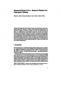
2.2 Actuation Considering dynamics, the most demanding requirements appear in the interaction with the environment. Impact forces, for instance, have to be considered for locomotion behaviors, but also and more importantly, developing cognitive behaviors such as manipulation might require exploring the environment erratically. As a consequence, it is likely that high impact forces need to be sustained by the robot mechanical structure. This requires strong joints, gearboxes, and more in general powerful actuators and appropriate elasticity (for absorbing impacts). In order to evaluate the range of the required forces and stiffness, various behaviors were simulated in a dynamical model of the robot. These simulations provided the initial data for the design of the robot. The simulations were run using Webots1 and were later crosschecked by traditional static analysis. At a more general level, we evaluated the available technology, compared to the experience within the project consortium and the targeted size of the robot: it was decided that electric motors were the most suitable technology for the iCub, given also that it had to be ready according to the very tight schedule of the overall project. Other technologies (e.g. hydraulic, pneumatic) were left for a “technology watch” activity and were not considered further for the design of the iCub. The actuation solution adopted for the iCub is based on a combination of a harmonic drive reduction system (CSD series, 100:1 ratio for all the major joints) and a brushless frameless motor (BLM) from the Kollmorgen frameless RBE series (Figure 1). The harmonic drive gears provide zero backlash, high reduction ratios on small space with low weight while the brushless motors exhibit the desired properties of robustness, high power density, and high torque and speed bandwidths (especially when compared with conventional DC brushed motors). The use of frameless motors permits integration of the motor and gears in an endoskeletal structure that minimizes size, weight and dimensions. Smaller motors (brushed-DC type) were used for the hands and head joints. An example on the use of this structure is depicted in Figure 2, which shows the shoulder of the iCub with details of the motor enclosure and tendon-driven pulley mechanisms.
2.3 Hand Certain features of the iCub are unique. Tendon driven joints are extensively used both for the hand and the shoulder, but also in the waist and ankle. This solution reduces the size of the robot but introduces elasticity that has to be considered in designing control strategies where high forces might be generated.
1
http://www.cyberbotics.com/products/webots/webots5.pdf
interestingly, both tendons are actuated by a single motor. In a second solution flexion is directly controlled by the tendon while extension is achieved by a spring return mechanism. This arrangement saves one cable per joint although it is less reliable in the presence of external forces perturbing the spring. Remarkably, this second solution has been used to move multiple joints in a coordinated way by means of a single motor (see for example intermediate and distal joint in Figure 3). Motion of the joints is driven by a single tendon routed via idle pulleys on the shafts of the connecting joints.
Figure 1: section of the standard brushless motor group of the iCub (Figure taken from [8]).
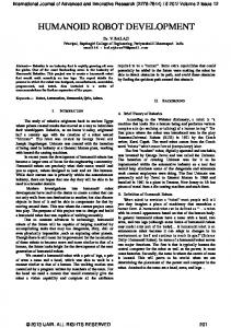
Figure 2: the shoulder of the iCub. Left: CAD schematics. Right: the implementation. Note the three DOF of the shoulder with intersecting axes of rotation and the placement of the actuators in the chest as indicated. 1.75mm steel cables join the movement of the motors with the pulleys actuating the joints.
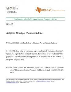
Figure 3 shows a cross section of the thumb finger with its two DOF: proximal and coordinated intermediate and distal joints. The index and middle fingers have an identical structure giving 4 additional degrees of freedom. The last two fingers are coupled together and pulled by a single motor which flexes simultaneously six joints (proximal, intermediate and distal). Two more motors are mounted directly inside the hand. A first motor is used for adduction/abduction movements of the thumb. A second one actuates the index, ring and little finger abduction in a coordinated way. In summary, eight DOF out of a total of nine are allocated to the first three fingers, allowing considerable dexterity. The last two fingers provide additional support to grasping. All motors except those mounted in the hand are equipped with magnetic incremental encoders. These measurements can be used to infer the joint position but are effected by errors due to the elasticity of tendons. Suitable embedded electronics and sensors have been designed in order to measure directly the hand joint angles. Sensing is achieved with commercial Hall-effect sensors coupled with custom made magnets. The overall size of the palm has been restricted to 50mm in length; it is 34mm wide at the wrist and 60mm at the fingers. The hand is only 25mm thick.
Figure 3 A cross section of the thumb finger. The proximal joint is flexed and extended by two different tendons, in red and green respectively. The intermediate and distal joints are flexed by a single tendon (in blue). Extension is achieved by means of two return springs. The stiffness of these springs determines the coordination of the two joints. The hand, for example, is fully tendon-driven. In order to actuate the overall 9 degrees of freedom, 7 motors are placed remotely in the forearm and 2 are embedded in the hand. A major design issue concerns the routing of the tendons from the forearm to the hand. In the final solution all tendons are routed through the wrist whose mechanical design (a 2 DOF differential joint) serves the purpose. Two different solutions have been adopted for actuating the hand joints. A first configuration (proximal joint in Figure 3) adopts two tendons: one for flexing and one for extending the joint;
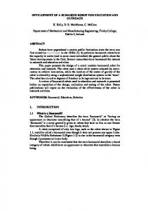
Figure 4: the hand of the iCub, showing the routing of the tendons through the wrist before full assembly is completed (the palm is missing). Tendons are made of Teflon-coated cables sliding inside Teflon coated flexible steel tubes.
2.4 Electronics The generation of motor control signals and sensory data acquisition is fully embedded into the iCub electronics. Further control layers are implemented externally. The interface between the iCub and the outside world occurs through a Gbit Ethernet cable. The robot contains motor amplifiers, a set of DSP
controllers, a PC104-based CPU, and analog to digital conversion cards. The low-level controller cards are of two types for the brushless and the brushed-DC motors respectively. They are based on the same DSP (Freescale 56F807). The controller of the brushless motors is made of two parts (logic and power) and can deliver a current of 6A continuous (20A peak) at 48V. All supply voltages are generated internally. The CAN bus is employed to communicate with the PC104 CPU. Logic and power are 58x42mm each and can control up to two motors. The power stage mounts also a metal heatsink that is then connected to the external shell of the robot for dissipation. Similarly the controller of the brushed-DC motors is made of two parts. One card acts as power supply; the other contains the CPU and amplifiers to control up to four motors. In this case the maximum continuous current is limited to 1A at 12V. More development is in progress to interface tactile and force/torque sensors as discussed for example in [8].
Figure 5: the brushless (left) and DC (right) motor control logic of the iCub. Transistors and heatsinks are not shown. The size of the PCBs is 58x42mm (left) and 80x30mm (right).
2.5 Sensors Given the size of the iCub, sensors were evaluated for performance but also weight and interface standards. The following table contains the list of available sensors and their status of maturity (i.e. integration into the robot hardware): Component
Model/type
Notes
Cameras
PointGrey Dragonfly 2 640x480 30fps
Firewire cameras, support also higher resolution
Microphones
MICRO POM2746L
Condenser electrect type
Inertial sensors
XSense MTx
3 gyroscopes, 3 linear accelerometers, compass
Force/torque sensors
Custom
Mechanically compatible with the ATI Mini-45
Position sensors
AS5045
12bit, absolute encoder
Position sensors
Faulhaber
Integrated position sensing for DC motors
Position sensors
Honeywell SS495A
Finger position sensing
Tactile sensors
Custom
Based on the AD7147, capacitive sensing [9]
magnetic
All sensors are fully integrated apart from the force/torque sensor whose control electronics is still under development and the skin whose entire technology is under testing. More information can be found in [8, 9].
3. SOFTWARE The iCub software was developed on top of Yarp [7]. RobotCub supported a major overhaul of the Yarp libraries to adapt to a more demanding collaborative environment. Better engineered software and interface definitions are now available in Yarp. Yarp is a set of libraries that support modularity by abstracting two common difficulties in robotics: namely, modularity in algorithms and in interfacing with the hardware. Robotics is perhaps one of the most demanding application environments for software recycling where hardware changes often, different specialized OSs are typically encountered in a context with a strong demand for efficiency. The Yarp libraries assume that an appropriate real-time layer is in charge of the low-level control of the robot and instead takes care of defining a soft real-time communication layer and hardware interface that is suited for cluster computation. Yarp takes care also of providing independence from the operating system and the development environment. The main tools in this respect are ACE [10] and CMake2. The former is an OS-independent communication library that hides the quirks of interprocess communication across different OSs. CMake is a cross-platform make-like description language and tool to generate appropriate platform specific project files. Yarp abstractions are defined in terms of protocols. The main Yarp protocol addresses inter-process communication issues. The abstraction is implemented by the port C++ class. Ports follow the observer pattern by decoupling producers and consumers. They can deliver messages of any size, across a network using a number of underlying protocols (including shared memory when possible). In doing so, ports decouple as much as possible (as function of a certain number of user-defined parameters) the behavior of the two sides of the communication channels. Ports can be commanded at run time to connect and disconnect. The second abstraction of Yarp is about hardware devices. The Yarp approach is to define interfaces for classes of devices to wrap native code APIs (often provided by the hardware manufactures). Change in hardware will likely require only a change in the API calls (and linking against the appropriate library). This easily encapsulates hardware dependencies but leaves dependencies in the source code. The latter can be removed by providing a “factory” for creating objects at run time (on demand). The combination of the port and device abstractions leads to remotable device drivers which can be accesses across a network: e.g. a grabber can send images to a multitude of listeners for parallel processing. Overall, Yarp’s philosophy is to be lightweight and to be “gentle” with existing approaches and libraries. This naturally excludes hard real-time issues that have to be necessarily addressed elsewhere, likely at the OS level.
2
http://www.cmake.org
3.1 Yarp example For the purposes of YARP, communication takes place through connections between named entities called ports. These form a directed graph, the YARP Network, where ports are the nodes, and connections are the edges. Each port is assigned a unique name, such as “/icub/camera/right”. Every port is registered by name with a “name server”. The goal is to ensure that the port name is the unique information a process needs in order to access the information supported by the port itself. The YARP name server converts from symbolic names to all the details necessary to make a connection with a specific resource. The YARP name server is designed to be easily used by clients who are not themselves using the YARP libraries or executables.
Similarly, specific modules are responsible for communicating with the control boards using the CAN bus. Specific ports are created by the modules in order to access position information and send commands to the robot joints.
The purpose of ports is to move data from one thread to another (or several others) across process and machine boundaries. The flow of data can be manipulated and monitored externally (e.g. from the command-line) at run-time. It can also be accessed without using the YARP libraries or executables, since the relevant protocols are documented. A port can send data to any number of other ports. A port can receive data from any number of other ports. Connections between ports can be freely added or removed, and may use different underlying transports. The use of several different transports and protocols allows us to exploit their best characteristics. TCP is reliable; it can be used to guarantee the reception of a message. UDP can be faster than TCP, but without guarantees. Multicast is efficient for distributing the same information to large numbers of targets. Shared memory can be employed for local connections. Figure 7 shows a very simple network of ports for basic access to the robot resources. In this example, the embedded PC104 is responsible for communicating with the hardware. Specific modules grab images from the right and the left cameras. Images are then available on the YARP network through dedicated ports.
Figure 6: the complete iCub prototype.
Figure 7: a simple sketch of the modules taking care of the interface with the cameras and the motor control boards. Similar modules (not represented here) take care of interfacing with other sensors such as microphones and inertial sensor.
4. CONCLUSION The design process of iCub has been a distributed effort within the RobotCub consortium. Various groups developed various subcomponents and contributed in different ways to the design of the robot including mechanics, electronics, sensors, etc. In particular, a whole design cycle was carried out for the subparts (e.g. head, hand, legs) and the prototypes that have been built and
debugged. The final CAD and 2D drawings were discussed and then moved to the integration stage. Clearly, communication was crucial at the initial design stage to guarantee a uniform design and a global optimization. Given the goals of the RobotCub project, the actual iCub design is primarily intended for studying manipulation as a complex cognitive task. This goal is reflected in the highly dexterous
hands, the flexible oculomotor system, and the dimensions of the bimanual workspace. These many constraints were considered in preparing the specifications of the robot and later on during the whole design process. Given the Open Source nature of the iCub, the development of the platform should never be considered ended. Numerous European projects have already planned to construct and develop copies of the iCub so as to study novel cognitive tasks together with the already mentioned manipulation. One of these projects, iTalk, has already proposed an outstanding framework based on the theoretical hypothesis that the parallel development of action, conceptualisation and social interaction permits the bootstrapping of language capabilities.
[3]
[4]
[5]
Additional initiatives aim at increasing the iCub community. RobotCub is giving away six copies of the iCub to the winners of an Open Call for proposals to use the iCub (recently concluded). In addition a structure called the Research and Training Site (RTS) has being created to support visiting researchers to work on the iCub prototypes in Genoa.
[6]
iTalk will contribute to these activities since four robots are expected to be delivered to some of the partners.
[7]
5. ACKNOWLEDGMENTS The authors were supported by European Union grant RobotCub (IST-2004-004370) and by iTalk (FP7 ICT-2007.2.1, grant no. 21566).
[8]
6. REFERENCES [1]
[2]
L. Fadiga, L. Craighero, and E. Olivier, "Human motor cortex excitability during the perception of others' action," Current Biology, vol. 14 pp. 331-333, 2005. L. Fadiga, L. Craighero, G. Buccino, and G. Rizzolatti, "Speech listening specifically modulates the excitability of tongue muscles: a TMS study," European Journal of Neuroscience, vol. 15, pp. 399-402, 2002.
[9]
[10]
G. Rizzolatti and L. Fadiga, "Grasping objects and grasping action meanings: the dual role of monkey rostroventral premotor cortex (area F5)," in Sensory Guidance of Movement, Novartis Foundation Symposium, G. R. Bock and J. A. Goode, Eds. Chichester: John Wiley and Sons, 1998, pp. 81-103. D. Vernon, G. Metta, and G. Sandini, "A Survey of Cognition and Cognitive Architectures: Implications for the Autonomous Development of Mental Capabilities in Computational Systems," IEEE Transactions on Evolutionary Computation, special issue on AMD, vol. 11, 2007. C. von Hofsten, "On the development of perception and action," in Handbook of Developmental Psychology, J. Valsiner and K. J. Connolly, Eds. London: Sage, 2003, pp. 114-140. G. Sandini, G. Metta, and D. Vernon, "RobotCub: An Open Framework for Research in Embodied Cognition," presented at IEEE-RAS/RJS International Conference on Humanoid Robotics, Santa Monica, CA, 2004. P. Fitzpatrick, G. Metta, and L. Natale, "Towards LongLived Robot Genes," Journal of Robotics and Autonomous Systems, Special Issue on Humanoid Technologies, vol. 56, 2008. N. G. Tsagarakis, G. Metta, G. Sandini, D. Vernon, R. Beira, F. Becchi, L. Righetti, J. Santos-Victor, A. J. Ijspeert, M. C. Carrozza, and D. G. Caldwell, "iCub – The Design and Realization of an Open Humanoid Platform for Cognitive and Neuroscience Research," Advanced Robotics, vol. 21, 2007. M. Maggiali, G. Cannata, P. Maiolino, G. Metta, M. Randazzo, and G. Sandini, "Embedded Distributed Capacitive Tactile Sensor," presented at The 11th Mechatronics Forum Biennial International Conference 2008, University of Limerick, Ireland, 2008. S. D. Huston, J. C. E. Johnson, and U. Syyid, The ACE Programmer's Guide: Addison-Wesley, 2003.