IMTC 2003 – Instrumentation and Measurement Technology Conference Vail, CO, USA, 20-22 May 2003
Identification and Prediction of a Moving Object Using Real-Time Global Vision Sensing G. Sen Gupta1,3, C. H. Messom2, S. Demidenko1 and Lim Yuen Siong3 1
IIS&T, Massey University, Palmerston North, New Zealand 2 II&MS, Massey University, Albany, New Zealand 3 School of EEE, Singapore Polytechnic, Singapore Email: G.SenGupta@ massey.ac.nz,
[email protected],
[email protected],
[email protected] Abstract – This paper presents a global vision based optical sensing system for identifying and intercepting moving objects. Using a color thresh-holding identification algorithm, the system can detect the position and angle of moving objects. The vision processing is done in real-time, effectively within 16.67ms sample time of an interlaced NTSC video image. Incremental tracking is employed to save on the vision processing time. Since odd and even fields are processed separately, there is inherent quantization noise in the system, which can be smoothed by using Kalman filtering. A case study of a robot goalkeeper behavior, including interception and clearance of ball, has been presented in detail. Based on the vision sensor data, a prediction technique is used to intercept the ball traveling towards goal. A state transition based algorithm for goalkeeper behavior is also introduced. Keywords – Vision sensing, Real-time Image Processing, Robotics Vision System, State Transition Based Control, Prediction
I.
INTRODUCTION
Vision systems (VS) are widely used in industry to track objects, detect intrusion, guide vehicles and mobile robots, as well as in applications in the sphere of medical science, automated inspection, production, etc. [1]. The VS is an integral component of any modern autonomous mobile robot. Local vision systems on mobile robots have significant limitations. Due to space constraints, dedicated hardware has to be used, which may be fast and reliable, but expensive and inflexible. In contrast, a global vision system is inexpensive and flexible. With modern, fast computing machines, processing speed is only a limited constraint. Improvement in the image processing algorithms has brought real-time vision processing into the realms of commodity hardware. Most commodity vision systems use video signals from a CCD camera as input to the image capture subsystems and so provide frame rates of approximately 30Hz or field rates of 60Hz for interlaced images. Processing these images with useful resolution (240 x 320 and above) in the 33.3 ms and 16.67 ms sample times respectively is a significant challenge. This paper examines the implementation of a global vision system which uses a single camera to detect and track several objects using incremental tracking [2]. In contrast to using two cameras employing overlapping tracking regions, as suggested in [2], the proposed system uses only one cam-
era. This is the case as the field of view is smaller in this current experimental setup and so does not require a dual camera system. With the reduced number of objects in this experiment it has been possible to increase the incremental tracking window size and yet keep the vision processing time within the sample period of 16.67ms. With larger tracking window size, the object being tracked is almost never ‘lost’. In the event it does, the fault tolerant software will fall back on fulltracking, whereby the whole image is analyzed, to ‘recover’ the object. A computationally inexpensive vision processing algorithm, using Run Length Encoding, has been discussed in papers [4, 5]. The RLE algorithm was applied to the problem of finding the difference between two binary images in [3]. Though the RLE algorithm can be implemented on commodity hardware in the robot soccer vision systems [6, 8], its significant processing speed advantage is when there are a number of objects to track. In this paper the system is restricted to only two objects, for which the proposed color thresh-holding blob-identification algorithm is adequate. To illustrate the accuracy of the vision sensing system, the paper presents a case of a robot goalkeeper exhibiting behaviors like intercepting the ball, clearing the ball from the goal area and sitting idle when the ball is in the opponent’s half of the soccer field. The behavior has been built on STBC (State Transition Based Control) approach [9]. There are two objects that need to be identified - the ball and the robot. For the robot, its position and its orientation need to be computed from the color patches. Filtering is employed on the vision data to smooth the quantization error due to separate processing of odd and even fields of the captured image. A predictive algorithm is used to calculate the path of the ball and to intercept it before it enters the goal. II. IDENTIFICATION COLOR PATTERN To facilitate identification of an object, e.g. a goal keeping robot, a color jacket is used comprising two color patches as shown in Figure 1. The centers of gravity of the two color
patches are first calculated from the image. The inclination of the line joining the two centers of gravity gives the orientation of the robot and the coordinates of the centre of this line is the position of the robot.
3.
For the ball, only the centre of gravity of the color patch is calculated since it has no orientation. The velocity of the ball can be used to add a direction vector to the ball position.
B. SECOND PASS (Step 5)
Y
Cr
Check if there are more pixels to consider then go to step 2, otherwise proceed to step 4. Find the lowest label for each equivalent set in the equivalence table – prepare the equivalence table
4.
5.
Scan the picture. Replace each label by the lowest label in its equivalent set.
Figure 2 shows a representation of the binary image where the 0's represents the background of the image and the 1's represent the objects of interest. It can be seen that there are two objects of interest in this image, one in the left part and the other in the right.
X Ct
Figure 1. Identification Color Pattern
III. BLOB DETECTION USING COLOR THRESHOLDING The tracking algorithm searches through the image, testing if a pixel belongs to one of the calibrated colours. The pixels are then grouped together to create the colour patches. Component labelling uses the sequential algorithm, which is a two-pass labelling technique [10]. The labels are identifiers that increment from the value of 1. Ideally the number of labels used is equal to the number of objects in the image with the required color. The procedure of testing the membership and grouping the pixels is made of 5 steps combined into two passes. A. FIRST PASS (Steps 1 to 3) 1. 2.
Scan the image in the incremental window from left to right, top to bottom If the pixel in the image is within the RGB threshold values of the colour of interest, then (a) If only one of its upper and left neighbours has a label, then copy the label. (b) If both upper and left neighbours have the same label, then copy that label. (c) If both upper and left neighbours have different labels, then copy the upper pixel’s label and enter the labels in an equivalence table as equivalent labels. (d) Otherwise assign a new label to this pixel and enter this label in the equivalence table.
0
0
0
0
0
0
0
0
0
0
0
0
0
0
0
0
1
1
1
0
0
0
0
0
0
0
0
0
0
0
1
1
1
1
0
0
0
0
0
0
1
0
0
1
1
1
1
0
0
0
0
1
1
0
1
0
0
1
1
1
1
1
1
0
0
1
1
1
1
0
0
0
0
0
0
0
0
0
0
0
0
0
0
0
Figure 2. The binary Image
0
0
0
0
0
0
0
0
0
0
0
0
0
0
0
0
1
1
1
0
0
0
0
0
0
0
0
0
0
0
1
1
1
1
0
0
0
0
0
0
2
0
0
3
1
1
1
0
0
0
0
4
4
0
2
0
0
3
1
1
1
1
1
0
0
4
4
4
2
0
0
0
0
0
0
0
0
0
0
0
0
0
0
0
Figure 3. The image after the first pass
Figure 3 shows the image after the first pass of the algorithm. Different objects have different labels. However due to a weakness in the first pass of the algorithm some of the objects have multiple labels associated with them, for example the object on the left with labels 3 and 1 and the object on the right with the labels 2 and 4. Figure 4 shows the image after the second pass of the algorithm, which resolves the problem of multiple labels for single objects. Having identified the separate objects, the centre of an object is calculated using a centre of gravity calculation.
0
0
0
0
0
0
0
0
0
0
0
0
0
0
0
0
1
1
1
0
0
0
0
0
0
0
0
0
0
0
1
1
1
1
0
0
0
0
0
0
2
0
0
1
1
1
1
0
0
0
0
2
2
0
2
0
0
1
1
1
1
1
1
0
0
2
2
2
2
0
0
0
0
0
0
0
0
0
0
0
0
0
0
0
Figure 4. Image after second pass
IV. THE STATE TRANSITION BASED CONTROL The data generated by the vision processor, namely the ball position and the position and orientation of the robot, is passed to the strategy server which uses a STBC approach to implement the robot behavior. The state transition diagram [9] for the goalkeeper behaviour is shown in Figure 5. S0 Initial State
S0S1
S0S3
S0S2
Clear the ball, when ball is within the goal area (G).
2.
Track ball position when ball is within the halfway line and the goal area (D).
3.
Idle in the goal centre position, when the ball is over the halfway line in the opponent area (O).
These three conditions represent the state of the goalkeeper. The main determining point is the position of the ball. To change state, the state transition conditions have to be met. The state transitions from the initialisation state are determined by the position of the ball. S0S1 - Change state if Ball position within goal area S0S2 - Change state if Ball position between goal area and centre line S0S3 - Change state if Ball position beyond centre line The transitions between S1, S2 and S3 are similarly determined. However, transition between S1 (clear the ball) and S3 (idle) is not possible. The ball travels at the maximum velocity of 1.5m/s. For the ball to move from region G to region O, which, at its shortest is a distance of 60 cm, it will take 400ms. Since the vision processor analyses one frame every 16.67ms, it will never fail to locate the ball when it crosses the region D. While the ball is in region D, the robot will exhibit behaviour of state S2 (track ball). V. PREDICTION FOR BALL INTERCEPTION
S2S3
S1S2 S1 Clear Ball
1.
S3 Idle
S2 Track Ball S2S1
S3S2
Figure 5. State Transition Diagram for Goalkeeper behavior
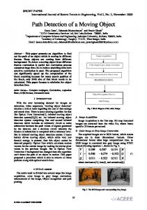
To test the robustness and accuracy of the colour sensing technique, three different behaviours of the goalkeeper have been proposed depending on the position of the ball on the field (Figure 6).
From the vision data, the velocity of the ball is calculated and updated every frame. The test of the accuracy of the vision system is in the success rate of the ball interception by the goalkeeper, in state S2 behavior, when the ball is moving towards the goal and is predicted to be entering the goal (Figure 7). GOALSIZE
GOALIESTANDX
Y (0, 0)
A X Robot
G
Ball Velocity vector
D
Ball
O 60 cms
ballYEstimate PhysicalY/2
Figure 7. Calculating the ball interception position Figure 6. Goal area, defensive and offensive regions of the field
The flow chart to predict where the robot must be positioned to intercept the ball is shown in Figure 8.
Calculate physical velocity vector (Ballvel.x and Ballvel.y) of ball from present and old positions
VI. EXPERIMENTAL SETUP AND RESULTS The experimental setup, shown in Figure 9, consists of a Pulnix 7EX NTSC camera and a Flashbus MV Pro image capture card [7].
Image Processing Station
Calculate m, gradient of line of ball motion, using velocity vector components
Strategy Server
Calculate constant in BallPos.y = m*BallPos.x + C Using ball position
Estimate the Y position where the ball crosses goal line ballYEstimate = m*0.0 + C
Is ball travelling towards & going to enter goal?
No
Figure 9. Experimental Setup
The image is captured at a resolution of 320x480 at a sampling rate of 30Hz. The odd and even fields are processed separately. Hence the effective image resolution is 320x240 delivered at a sampling rate of 60Hz. The image captured is processed on a 450MHz Pentium II PC with 128MB RAM. The data from the vision processing is passed to the strategy server running on the same PC. The image capture card was configured for off-screen capture, as shown in Figure 10.
Yes Set final Y position to m*GOALIESTANDX + C
Video
Capture Card
Set final X position to GOALIESTANDX and position robot at the final position
VGA Card RAM
CCD Camera PCI Bus System RAM Figure 8. Flow chart for predicting the point of interception
As can be seen from the flow chart, if the ball position is not detected accurately, the robot is very unlikely to intercept the ball. This is even more so when the ball is traveling at a very high or very slow speed. At a high speed the time available for the robot to reach the target position is very small. For slow speeds the numerical accuracy of finding the angle of the direction of the ball is low, making the calculation of the target position very noisy. For low ball velocities, just tracking the current Y position of the ball is more stable.
Figure 10. Image capture in off-screen capture mode
The vision processing completed in 6ms, which allowed a margin of over 10ms to complete the strategy calculations. The STBC strategy implementation is computationally efficient even for sophisticated behaviors and so completes well within the real-time constraints. The robot angle was calculated with an accuracy of +/- 5 degrees and the position with an accuracy of +/- 0.5cms.
In order to improve the accuracy of angle calculation, experiments with the color jacket shown in Figure 11 were performed. The centre of gravity of the individual color patch is farther apart as compared to the arrangement shown in Figure 1. This improved the accuracy of angle measurement to +/- 3 degrees.
Currently, work is being done on using Kalman filtering to minimize quantization errors in stationary objects. The research findings will be reported in a dedicated to it paper. VIII. ACKNOWLEDGEMENTS The collaborative work was supported by a grant from ASIA 2000 HEEP funds and carried out jointly at Massey University and the Advanced Robotic and Intelligent Control Centre, Singapore Polytechnic.
Y
Cr
REFERENCES [1]
X
Ct
Figure 11. Color jacket to improve angle accuracy
With uniform lighting conditions, and the initial position of the robot inline with the goal line, the robot was able to intercept the ball on every shot – at slow ball speeds as well as at high speed up to 1.5m/sec, thus proving the robustness of the vision tracking system. The maximum speed of robots is approximately 1.5m/sec, so this experiment is realistic. In a real game situation the robot may not be initially inline with the goal line, such as when the ball is being cleared from the goal area or the robot has just blocked a shot. Due to these reasons the robot is not able to block all shots in a real game situation. VII. CONCLUSIONS Tracking moving objects in real time with high accuracy is a significant technical challenge using commodity hardware. The system presented in this paper can track two objects in real time with a resolution of 0.5cm. The strategy layer builds on the accurate vision data to implement a very robust and reliable control of a robot. The proposed system is applicable in industrial environment where it is required to track mobile objects and in situations where objects need to be intercepted in time to avoid a collision. Future developments will encompass extension of the proposed system to tracking several objects moving randomly at high speed. Research challenge would be to address the vision processing time for multiple objects and without violating the real-time constraint.
R. Templer, H. Nicholls and T. Nicolle, "Robotics for meat processing - from research to commercialisation", Industrial Robot, Vol 26, Number 4, 1999. [2] C.H.Messom, G.S. Gupta and H.L. Sng, "Distributed Real-time Image Processing for a Dual Camera System", CIRAS 2001, Singapore, 2001 pp 53-59. [3] F. Ercal, M. Allen, and F. Hao, "A Systolic Image Difference Algorithmfor RLE-Compressed Images", IEEE Transactions on Parallel and Distributed Systems, Vol. 11, No. 5, May 2000. [4] C.H.Messom, S. Demidenko, K. Subramaniam and G. Sen Gupta, “Size/Position Identification in Real-Time Image processing using Run Length Encoding”, IMTC, Alaska, USA, 2002, pp 1055-1059 [5] J. Bruce, T. Balch and M. Veloso, "Fast and Inexpensive Color Image Segmentation for Interactive Robots", IROS 2000, San Francisco, 2000 [6] H. Kitano, M. Asada, Y. Kuniyoshi, I. Noda, E. Osawa and H. Matsubara, "RoboCup: A Challenge Problem for AI", RoboCup-97: Robot Soccer World Cup I, Springer Verlag, London, 1998. [7] http://www.integraltech.com/Products/FrameGrabbers.html [8] J. Baltes. "Practical camera and colour calibration for large rooms". In Manuela Veloso, Enrico Pagello, and Hiroaki Kitano, editors, RoboCup-99: Robot Soccer World Cup III, pages 148-161, New York, 2000. Springer. [9] G. Sen Gupta, C.H. Messom and Sng HL, “State Transition Based Supervisory Control for a Robot Soccer System”. DELTA2002, Christchurch, New Zealand, 2002, pp 338–342 [10] M. Ramesh Jain, R. Kasturi, and B.G. Schunck, Machine Vision, McGraw-Hill International Editions, Computer Science Series, International Edition 1995