amplifiers. Obviously, the GNURadio spectrum contains peaks at fc ì 6MHz that are not present in the Atheros spec- trum. Furthermore, frequencies at the edge ...
6th Karlsruhe Workshop on Software Radios
IEEE 802.11p Transmission Using GNURadio P. Fuxjäger∗ , A. Costantini∗† , D. Valerio∗ , P. Castiglione∗ , G. Zacheo∗ , T. Zemen∗ , F. Ricciato∗† ∗ Forschungszentrum Telekommunikation Wien, Donau-City-Strasse 1, A-1220 Vienna, Austria † University of Salento, 73100 Lecce, Italy E-mail: {fuxjaeger, costantini, valerio, castiglione, zacheo, zemen, ricciato}@ftw.at Abstract—In this work we present an implementation of a fully functional IEEE 802.11p transmitter in software-defined radio. We describe the rapid-prototyping methodology that was used to implement the frame-encoder within the open-source GNU Software Radio (GNURadio) platform [1]. The encoder generates OFDM frames in digital complex base-band representation and uses the USRP2 [2] as digital-to-analog front-end for up-conversion and final transmission. Since the actual encoding process involves a large number of complex steps we split the development approach into three sequential stages. First, a reference-encoder in a high-level language (MATLAB) is derived from the IEEE standard documents. Second, the individual blocks of the MATLAB encoding chain are progressively ported to GNURadio, cross-checking with the reference after each step. Finally, standard compliance is verified by conducting comparative over-the-air measurements with an early prototype of a commercial 11p transceiver. Initial measurement results indicate that the fidelity of the resulting GNURadio implementation is on par with non-software-defined radio industry solutions and capable of generating truly standard-compliant OFDM frames. The encoder presented here has been released under GPLv3 and is also capable of encoding frames according to the 11a and 11g amendments, thus making it a valuable building block for upcoming software-defined radio projects.
I. I NTRODUCTION AND RELATED WORK The IEEE 802.11p standard (which will be finalized in late 2010 [3]) aims at providing reliable wireless communication for vehicular environments. It will serve as an underlying protocol for future car-to-car and car-to-infrastructure applications worldwide. At the physical layer it has essentially the same structure as 802.11a and 802.11g: the modulation format, based on orthogonal frequency-division multiplexing (OFDM), the forward-error-correction (FEC), the structure of the preamble-sequences and the pilot-symbol schemes are identical. Furthermore, 802.11p uses the same medium access scheme common to all IEEE 802.11 standards, known as carrier sensing multiple access with collision avoidance (CSMA/CA) [4]. In the current draft version of the standard, the frame encoding procedure for IEEE 802.11p differs from 11a and 11g only in two key aspects: the operating frequency-band is shifted to around 5.9GHz and the duration of OFDM symbols is doubled from 4μs to 8μs. The rationale behind these modifications is the following: first, using a dedicated part of the spectrum reduces interference with legacy systems, The Telecommunications Research Center Vienna (FTW) is supported by the Austrian Government and the City of Vienna within the competence center program COMET. The work of Paul Fuxäger, Andrea Costantini, Danilo Valerio, Giammarco Zacheo, Thomas Zemen and Fabio Ricciato has been supported by the FTW projects I-0 and N-0. The work of Paolo Castiglione has been supported by the Austria Science Fund (FWF) through grant NFN SISE (S106).
second, doubling the symbol-time also means doubling the cyclic-prefix-duration, i.e. decreasing the OFDM inter-symbolinterference (ISI) in outdoor channels. Given that the original IEEE 802.11a/g standards have been designed for low mobility and indoor usage, the question arises whether these two (minor) changes are sufficient to make 802.11p suitable for vehicular communication. The research community has already started analyzing 802.11p link-layer performance by using simulation tools but we believe that only real-world experiments can reliably evaluate the robustness of the standard in high-mobility scenarios. Due to the current lack of commercial 802.11p chipsets, using a software-radio prototype is an attractive basis for conducting these empirical measurements. We present the implementation of an IEEE 802.11p frameencoder on the open-source GNURadio platform and outline the methodology that was used during the development process. The encoder generates OFDM frames in digital complex base-band representation and uses the USRP Version 2 [2] as digital-to-analog front-end to up-convert and transmit them in the 5.9GHz band that has been allocated for dedicated short range communication (DSRC) for vehicular applications. GNURadio-based encoders for other communication standards are already publicly available (e.g. [5]). To the best of our knowledge, this is the first implementation that is capable of generating and transmitting frames for the OFDM-based IEEE 802.11p standard. Additionally, since the aforementioned differences to the original standards are so marginal, the encoder we built is also capable of generating frames for 11a and 11g just by changing two parameters (interpolation factor and carrier frequency) in the front-end. II. D EVELOPMENT M ETHODOLOGY The first step in the development procedure was to create a reference-encoder for OFDM frames in MATLAB, using the detailed instructions of the encoding scheme given in the IEEE 802.11-2007 standard document [4]. The reason for taking this intermediate step using MATLAB is that it speeds up the development process as it provides a valuable debugging tool for the final GNURadio-based encoding chain. We followed the encoding recipe outlined in [4, paragraph 17.3.2.1] and subsequently validated the resulting MATLAB code by comparing its output with the reference-frame (a table of 881 complex numbers) that is included in [4, Annex G]. A preliminary test-measurement was done by saving the MATLAB output to disk, using this file as input-source for the USRP2, and decoding the transmitted signal with a conventional WiFi receiver. During these trial-runs we discovered that
83
6th Karlsruhe Workshop on Software Radios
Table I D EVELOPMENT-S YSTEM D ETAILS Distribution Kernel Version Platform GNURadio Version Python Version USRP2 HW revision number USRP2 Firmware revision Daughterboard model Carrier-frequency during test
IEEE802.11 P OFDM KEY
Ubuntu 9.10 2.6.31-16-generic x86 64bit 3.2.2 2.6.4 0x0301 r11370 XCVR2450 5.88GHz (Channel 176)
� �� �� ��
�� �����
��� ����������� ����������
� � �� �� ����������� ����������
������������ �
�� �����
�� ����
� ����������� ���
���������� ���������
�� �����
�� ����
������������� ��������� ��������
��� � ���������� ���������
�� �� ������
�� �� ����� � � �
� ����� �������� �������
�����
�� �����
�� ����
����� �� �������� �������
���� �����
� ����� � ��� ��� ����� ��� ����
� � � ���� �
�� �����
�� ����
� ����� � ����
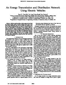
Figure 1. A flow-graph of the encoding process. The resulting complex baseband samples are subsequently up-converted and transmitted by the USRP Version 2.
a bug in the USRP2 firmware swaps in-phase and quadrature parts in the up-conversion process. This routing bug has been already been fixed by Ettus Research LLC developers in recent firmware revisions. For complete version information of our test-equipment see Table I. In the second phase of development we progressively ported the MATLAB encoding chain to the GNURadio framework. An important objective was to reuse signal-processing blocks that are already available in GNURadio whenever possible. A representation of the resulting flow-graph is depicted in Figure 1. In this phase, it is crucial to understand that GNURadio distinguishes between stream-based operation and block-based operation. Adopting the purely block-based approach of our original MATLAB code was not an option since it would have resulted in highly sub-optimum GNURadio code in terms of latency of the encoding process. Consider for example a long frame consisting of several hundred OFDM symbols. In case of pure block-based implementation, each function in the encoding chain (c.f. Figure 1) would need to process the whole frame before producing output for the subsequent block. This would prohibit any parallelization of the encoding procedure and thus increase the latency of the system. A straightforward solution to get around this problem is to use the GNURadio scheduler, which is capable of orchestrating streams of input/output data between processing blocks and controls the required buffering logic. In our case, the conversion from block to stream occurs in the symbol-mapper block. The input to this block is a complete physical-layer convergence protocol data unit (PLCPDU) (the
84
Table II
PARAMETERS , ACCORDING TO DRAFT STANDARD DOCUMENT [6].
Number of data subcarriers Number of pilot subcarriers Subcarrier frequency spacing Occupied Bandwidth Short training sequence duration Long training sequence duration Training sequence guard interval PLCP preamble duration Guard interval duration OFDM Symbol duration
48 4 156.2kHz 8.28125MHz 16μs 16μs 3.2μs 32μs 1.6μs 8μs
block of bits that is encoded in one OFDM frame). The output is a stream of complex symbols (grouped in chunks of 48 elements because IEEE802.11 OFDM standards use 48 data subcarriers, see Table II). Essentially, the processing blocks that follow after the symbol-mapper take a chunk of complex symbols - corresponding to a single OFDM-symbol - and perform the respective transformations on them, immediately producing output for the subsequent processing block in the chain. This procedure is repeated for each OFDM-symbol in the frame. However, IEEE 802.11a/g/p OFDM standards use use a very specific method to insert pilot information in each OFDMsymbol: the complex symbols that are mapped on the four pilot subcarriers are different for each OFDM symbol. They change polarity according to a specific binary sequence, so the pilotinsertion function needs to be aware of which symbol in the frame is being processed. In order to account for these special encoding-rules we implemented an internal global counter in the pilot-insertion processing-block. III. VALIDATION R ESULTS The third phase of development was dedicated to a final quality-check of the complete implementation (basebandencoder plus front-end) using over-the-air measurements. We ran the transmitter-code using a desktop-PC with 4 GBytes of RAM and an Intel Core 2 Duo E8400 CPU clocked at 3 GHz. The integrated 1000Base-T Ethernet interface was connected to the USRP2, equipped with a XCVR2450 daughter board which supports operating frequencies ranging from 2.4 − 2.5 GHz, and 4.9 − 5.9 GHz [2]. Additional details of our testsystem are summarized in Table I. The measurement-campaign was conducted using a combination of various methods: first, we used a second machine connected to another USRP2 to down-convert and record the transmit signal. This was done in order to evaluate the shape of the resulting power-spectrum at the transmitter-output. Second, using symbol-time settings in accordance with 802.11g and a carrier-frequency in the 2.4GHz ISM band we generated frames that were correctly received by a conventional 802.11g chipset [7]. Third, we tried to verify the compliance with 802.11p by conducting comparative measurements using an early prototype-transceiver, based on a modified Atheros chipset. This device is being used in the CVIS project [8] and was kindly provided to us by the Institute of Communications
6th Karlsruhe Workshop on Software Radios
and Radio-Frequency Engineering at Vienna University of Technology [9]. Throughout the whole campaign a non-timevarying and interference-free measurement channel was established between transmitter and receiver units using a directcable connection in combination with fixed power-attenuators. A. Shape of TX Power-Spectrum The results shown in Figure 2 and Figure 3 demonstrate the differences in the transmit power-spectrum between our GNURadio-based implementation and the industry-prototype chipset. They correspond to the output of the FFT spectrumanalyzer tool that is included in the GNURadio framework and in both cases the transmit-signal consisted of maximumlength frames that were continuously generated using low transmit-gain levels in order to avoid non-linearities in the amplifiers. Obviously, the GNURadio spectrum contains peaks at fc ± 6MHz that are not present in the Atheros spectrum. Furthermore, frequencies at the edge of the main band (fc ± 4MHz) are attenuated, visible in the strong curvature around fc . We think that these imperfections in the shape of the power spectrum are due to the roll-off characteristics of the interpolation filter in the up-conversion processing of the USRP2. This problem could be fixed by doing part of the interpolation already in the GNURadio encoder and using a lower interpolation factor in the USRP2. Note that in Figure 2 the GNURadio transmit-signal also seems to contain a carriercomponent while in the Atheros spectrum the fc = 5.88GHz carrier seems to have much less power than the other carriers (we will show consequences of this in subsection III-C). B. Frame-Error-Ratio vs SNR Performance Another side-by-side comparison of the two transmitsources is presented in Figure 4. These measurement curves depict the frame-error-ratio as observed by the Atheros chipset (which provides a measure of received SNR via the signal strength (RSSI) readout). The bold curves relate to the FTW GNURadio transmitter performance, each measurement-point corresponding to 105 sent frames. Although we have shown in Figure 2 and Figure 3 that the shape of the power-spectrum is clearly sub-optimum, the GNURadio implementation performance in terms of FER vs. SNR as observed at the Atheros receiver is at max 0.5 − 1dB worse than the Atheros-based transmitter in the low-to-medium SNR region. This indicates that the local-oscillator drift and phase-noise characteristics of the USRP2 are on par with the industry-chipset. C. Baseband-Signal Analysis However, when using the GNURadio transmitter in the high-SNR region (beyond 21dB in Figure 4) the Atheros-based receiver starts to show some unexpected behavior. The number of detected (but corrupted) frames exceeds the number of actual sent frames and the FER measurement-method becomes unusable (thus the missing points beyond 21dB in Figure 4 for the GNURadio transmitter). We conjecture that the main reason for this phenomenon are spurious emissions at the output of the USRP2 which are constantly present as soon as
Figure 2. Power Spectrum of the GNURadio implementation, recorded with a second USRP2. Attenuated direct cable connection, USRP2 TX-gain of 5dB and carrier-frequency fc = 5880MHz. The red line corresponds to the class A spectrum mask that is defined in the IEEE802.11p Draft 9.0 standard document.
Figure 3. Power Spectrum of the Atheros-based prototype, recorded with the USRP2. Again, a direct cable connection was used in combination with a low gain setting in the transmitter.
the GNURadio encoder software initializes the daughterboard hardware. It triggers the carrier-sensing mechanism in the Atheros-chipset which results in the receiver-logic trying to sync on the spurious signal and missing the actual frame transmission. The comparison shown in Figure 5 and Figure 6 confirms this hypothesis. The complex digital baseband signal that is sent to the USPR2 by the GNURadio encoder (Figure 5) does not contain any DC component. After up-conversion, transmission, reception and down-conversion (using another USRP2 at the receiver-side) a DC component is present for the complete time duration the transmitter-side USRP2 is active (Figure 6). This problem cannot be easily fixed by adapting the GNURadio encoder software as it is caused by the XCVR2450 daughterboard. IV. C ONCLUSION AND F UTURE W ORK We have shown a method to rapidly prototype a fully standard-compliant OFDM frame encoder using the GNURadio framework and the Universal Software Radio Peripheral (Version 2). Since the actual encoding procedure involves a large number of complex processing steps it is crucial to split up the development approach into sequential stages. First, a reference-design in a high-level language is derived from the standard documents. Subsequently, single parts of the reference encoder are ported to the target platform in a stepby-step fashion. A final measurement-based evaluation phase
85
6th Karlsruhe Workshop on Software Radios
0 10
Frame−Error−Ratio
−1 10
−2 10
Ath TX, 64QAM, r=0.75, 27Mbit/s. Ath TX, 64QAM, r=0.66, 24Mbit/s. Ath TX, 16QAM, r=0.75, 18Mbit/s. FTW TX, 64QAM, r=0.75, 27Mbit/s. FTW TX, 64QAM, r=0.66, 24Mbit/s. FTW TX, 16QAM, r=0.75, 18Mbit/s.
−3 10
−4 10 10
11
12
13
14
15
16
17 18 SNR [dB]
19
20
21
22
23
24
25
Figure 4. This figure displays the frame-error-ratio over received SNR using two types of transmitters (Atheros based prototype and the FTW GNURadio implementation) in a non-time-varying, interference-free channel (direct cable connection with 90dB fixed attenuation). In both cases another Atheros prototype is used to decode the frames and calculate the received signal strength (RSSI readout). A maximum MPDU-length of 1612bytes per frame, consisting of 1574bytes MSDU payload, 30 bytes MAC-header and 4 bytes CRC was used for the measurement-run presented in this figure.
0.3
0.25
Magnitude
0.2
0.15
0.1
0.05
0 0
1000
2000
3000 4000 Sample Index
5000
6000
Figure 5. Magnitude of the complex digital baseband representation of a frame before it is sent to the USPR2 for up-conversion and transmission. 0.3
0.25
Magnitude
0.2
0.15
0.1
0.05
0 0
1000
2000
3000 4000 Sample Index
5000
6000
Figure 6. The exact same frame as in Figure 5 after digital up-conversion, transmission, reception and digital down-conversion. The DC component that is visible after the frame burst has finished is likely to be caused by imperfections in the XCVR2450 daughterboard.
86
using standard-compliant receivers completes the development process. The resulting GNURadio-based transmitter is able to generate OFDM frames fully compliant with IEEE 802.11a, 802.11g, and 802.11p standards. Our next goal is to implement the complementary OFDM frame-decoder in GNURadio. Merging this receiver with the transmitter implementation would provide the basis for a fully interactive software-radio transceiver that includes basic medium-access functionalities such as carrier-sensing and transmission of acknowledgment frames. One important goal is to get as close as possible to the stringent frame-timing constraints that need to be maintained in order to be compliant with IEEE 802.11 standards. R EFERENCES [1] Official GNU software radio website. http://gnuradio.org/trac. [2] Ettus Research LLC website. http://www.ettus.com. [3] 802.11 Timelines of the Institute of Electrical and Electronics Engineers. http://grouper.ieee.org/groups/802/11/Reports. [4] IEEE 802.11-2007. Wireless LAN Medium Access Control (MAC) and Physical Layer (PHY) Specifications. http://standards.ieee.org/getieee802/download/802.11-2007.pdf. [5] V. Pellegrini, G. Bacci, M. Luise, "Soft-DVB, A Fully Software, GNURadio Based ETSI DVB-TModulator," 5th KarlsruheWorkshop on Software Radios, March 2008, Karlsruhe, Germany. [6] Wireless LAN Medium Access Control (MAC) and Physical Layer (PHY) specifications - Amendment 8: Wireless Access in Vehicular Environments. IEEE802.11p Draft 9.0. [7] RT2500 chipset device list. http://ralink.rapla.net. [8] The CVIS project website. http://www.cvisproject.org. [9] Institute of Communications and Radio-Frequency Engineering, Vienna University of Technology. http://www.nt.tuwien.ac.at/.