IEEE TRANSACTIONS ON INSTRUMENTATION AND MEASUREMENT, VOL. 55, NO. 2, APRIL 2006
615
IEEE802.11 Sensor Networking Paolo Ferrari, Member, IEEE, Alessandra Flammini, Member, IEEE, Daniele Marioli, Member, IEEE, and Andrea Taroni, Member, IEEE
Abstract—This paper deals with a smart-transducer wireless network for industrial applications. Thanks to its high popularity, a solution based on IEEE802.11 (also known as wireless fidelity or Wi-Fi) is experimentally investigated. A master–slave network organization is proposed to allow several sensors to be connected with generic Wi-Fi devices like PCs; a proprietary protocol over Internet Protocol (IP)/User Datagram Protocol (UDP) has also been developed. Last, some low-cost prototypes have been built to test the network behavior performances in terms of timing characteristics and power dissipation. Experimental results prove the applicability in a soft real-time (nontime-critical) industrial context. Index Terms—IEEE802.11, Internet Protocol (IP), sensor network, smart sensor, Wireless Ethernet.
I. I NTRODUCTION
I
N A MODERN industrial plant, there are thousands of transducers, and a significant part of the total cost is due to cables. Even if wireless technology advantages are very attractive today (e.g., better mechanical reliability in hostile environments, scalability etc.), the industrial market still prefers cabling. Since the consumer market is evolving toward pervasive wireless applications, and this trend will result in a general cost reduction for all wireless-communication devices and chipsets, many vendors are proposing standard-based and proprietary wireless products ready to be also used in industry. Generally, a system that uses proprietary hardware and protocols could lack compatibility [1] if compared with a standard-based system; however, it can offer superior performance and lower power consumption, since it can be finely trimmed on client requirements. Wireless networks based on international standards seem to be a good option because, although they cannot reach a full optimization, they are widely known and supported. Table I summarizes the key networking parameters of wireless standards that are relevant for industrial applications: Bluetooth (BT) [2], Wireless Ethernet [IEEE802.11 wireless fidelity (Wi-Fi)] [3], and the recent IEEE802.15.4 [4] (physical (PHY) and media access control (MAC) of ZigBee). IEEE802.11 is usually utilized in PC-based systems, and it could seem unsuitable for sensors. Up to now, simpler BT-based solutions are available [5]; actually, BT could be preferable with respect to IEEE802.11, as shown in [6] and [7]. On the other hand, IEEE802.11 is a part of the famous IEEE802 Manuscript received June 15, 2004; revised October 19, 2005. The authors are with the Department of Electronics for Automation and Istituto Nazionale Fisica della Materia (INFM), University of Brescia, 25123 Brescia, Italy (e-mail:
[email protected]). Digital Object Identifier 10.1109/TIM.2006.870105
family (Ethernet-based environment); therefore, IEEE802.11 components [8] are commonly employed to extend industrial Ethernet links. Moreover, it is a matter of fact that in a factory there is a network stratification where each layer operates at a different level, from a single automation cell up to the administration; if a smart transducer is able to talk with high-level protocols, bottleneck can be avoided since no (or less) gateways are needed. Since the Internet and the Web offer the highest degree of standardization, a wireless-transducer supporting Internet Protocols (IPs) can be greatly advantaged. IEEE802.11 has not yet been considered for the sensor level; therefore, our objective is to show the feasibility of a WirelessEthernet sensor network for some industrial applications, i.e., where a brush-powered rotating part must be connected to a wired network of the fixed part, or where wireless sensors or actuators must be added to a wired network for diagnostic, commissioning, or redundancy. Clearly, such applications are not time critical, since wireless technologies are intrinsically unreliable and nondeterministic. To evaluate if the Wireless Ethernet sensor network can be used instead of a traditional field bus, this work investigates about the possibility of a low-cost IEEE802.11 interface for an 8-bit microcontroller-based sensor, experimentally exploring its performances. Expected result will be a small network (less than five nodes) characterized by a cycle time less than 20 ms (compatible with many industrial applications and diagnostic tasks); a total power dissipation slightly higher than the radiomodule power dissipation; and a software realization that uses less than a half of the computational power of a low-cost microcontroller. II. P ROPOSED A PPROACH Wireless Ethernet architecture is essentially a cellular-type network with wireless stations and fixed base stations [access point (AP)]. If a cell has no base stations, active stations can directly communicate each other, provided that their ranges overlap. This network topology is called ad hoc network. The proposed approach is shown in Fig. 1(a), where several IEEE802.11 wireless transducers belong to the same ad hoc network together with other Wi-Fi devices. There is no difference between a PC and a wireless transducer, and generally, information can be exchanged peer-to-peer without any rule. Moreover, the proposed wireless network can be linked with an already-present wired-Ethernet segment by means of an AP, as illustrated in Fig. 1(b). AP extends the wireless subnetwork coverage, and it enables wireless network traffic to be transmitted over a preexisting fixed network, overcoming
0018-9456/$20.00 © 2006 IEEE
616
IEEE TRANSACTIONS ON INSTRUMENTATION AND MEASUREMENT, VOL. 55, NO. 2, APRIL 2006
TABLE I NETWORKING PARAMETERS OF WIRELESS STANDARDS RELEVANT FOR INDUSTRIAL APPLICATIONS. CARRIER SENSE MULTIPLE ACCESS WITH COLLISIONS AVOIDANCE (CSMA/CA); AND TIME DIVISION MULTIPLE ACCESS (TDMA)
Fig. 1. Proposed architecture. (a) Wireless-transducer network with an ad hoc topology. (b) More general wireless-transducer network with an AP and a wiredEthernet backbone.
Fig. 2. Block diagram of the proposed wireless transducer (S is for sensor, A is for actuator).
any range limitation and allowing merging of different wireless subnetworks. The logical architecture of the proposed system is a master/ slave, because in industrial applications such organization offers a reliable solution that keeps the network-traffic low (e.g., no collisions) and produces repeatable results. Anyway, this solution is open to any architecture expansion; as an example, each network entity can be a master or a slave and, since everyone is visible within the same cell, master rights could be passed to each other (e.g., by means of a “token”). The conceptual block diagram of the proposed wireless transducer is shown in Fig. 2 together with a sensor (S) and an actuator (A). There are three main parts: Transducer interface and signal processing blocks are common to any smart sensor, while IEEE802.11 MAC and RF section are specific of a WiFi equipped transducers. Nowadays, in a smart sensor, signal processing is always performed by a microcontroller (or a DSP) and, in order to keep costs low, such device should also furnish an adequate support to communication algorithms and interfaces. In effect, network protocols require more computational power than the traditional point-to-point ones, and the communication stack must be carefully adapted. Since transducer interface and signal processing depend on specific realization and application of a wireless device, they are not treated here. In the following, only problems related to
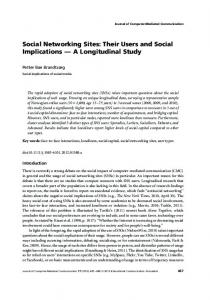
Fig. 3. Photograph of the prototype of the proposed IEEE802.11 enabled sensor.
networking are considered, while the transducer is substituted with generic I/O lines (analog or digital). III. S YSTEM D ESCRIPTION The proposed IEEE802.11 sensor network is composed of hardware prototypes and a software protocol. A. Hardware Prototype A prototype has been built, as shown in Fig. 3, in order to evaluate a real IEEE802.11 sensor network. Each Wi-Fi transducer has an analog input channel (0–3.3 V), eight digital inputs, and eight digital outputs. The core of the system is a low-cost 8-bit microcontroller PIC18LF452 from a Microchip with 32 kB of flash-type program memory and 1536 B of RAM; other integrated peripherals used in the prototype are the 10-bit analog-to-digital converter and two 16-bit timers. An Orinoco Silver Personal Computer Memory Card International Association (PCMCIA) card from Lucent has been adopted as IEEE802.11b MAC and PHY device (11 Mb/s). This kind of solution is very effective since cheap wireless PCMCIA cards can be found in every
FERRARI et al.: IEEE802.11 SENSOR NETWORKING
617
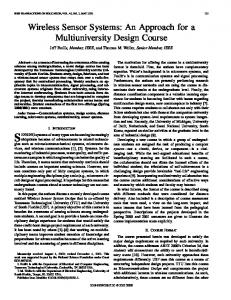
Fig. 4. Proposed protocol messages [(b) master and (c) slave)] and their position inside the (a) Wireless Ethernet packet. Length, expressed in bytes, is indicated for each field.
computer shop, while single components of an IEEE802.11 chipset must be purchased in lots of thousands. Moreover, if well-industrialized and standard-compliant RF devices are employed, layout design of the prototype is greatly simplified. Orinoco card must be inserted into a standard 68-pin socket and the PCMCIA bus interface has been implemented with a Cypress CY37128 complex programmable logic device (CPLD); it hosts a state machine that helps the microcontroller to access sequentially the registers required to drive the 16-bit wide PCMCIA bus. Both microcontroller and CPLD operate at a main clock frequency of 20 MHz. The power-supply section serves transducers, logic circuits, and IEEE802.11 module. It can accept input from a fixed source or from a mobile source like a battery or a solar cell. It should be said that all used devices can support 3.3-V operations but the prototype works at 5 V because of Orinoco Silver Card constrains (PCMCIA “standard mode”). The use of a double side printed circuit board (PCB) technology with through-hole components and the dimensions of the PCMCIA card lead the prototype to be 200 mm in length and 95 mm in width. This result is acceptable for a feasibility study; obviously, a practical implementation to be used in a true sensor application will require smaller devices based on surface mounted device (SMD) components and custom radio modules.
B. Software The proposed system relies on a well-tailored protocol stack (i.e., a set of protocols) based on IEEE802.11, but it is also ready to connect with Internet. Wireless Ethernet protocol is directly derived from standard IEEE802.3. IP is fundamental in every application that could be interconnected with a global network, so it has been implemented as a basis; a transport-layer protocol should be put over it. The Internet stack offers two transport protocols: User Datagram Protocol (UDP) and Transfer Control Protocol (TCP). The first one is simpler; in fact, it accommodates few information allowing link data multiplexing (virtual “ports”
over the same network link); the second one is a powerful connection-oriented protocol that guarantees a reliable transport providing retransmission of lost data packets. Noticeably, TCP software is more complex and, even though solutions optimized for a microcontroller were proposed in [9] and [10], the sole TCP stack requires 16 kB of ROM and 800 B of RAM in a PIC18F452, consuming more than 10 ms to be processed. For these reasons, UDP has been used in this work. In addition, Address Resolution Protocol (ARP) and Internet Control Message Protocol (ICMP) must be implemented to assure proper operations. Last, a suitable application protocol has been designed over UDP, as reported in Fig. 4(a), together with the well-known Ethernet frame. The proposed protocol is proprietary and its operation is typical of a master–slave architecture; the master interrogates each slave waiting for a response. Messages from the master to the slave [Fig. 4(b)] have the following fields. 1) Destination: Indication of which slave is the destination of the message. This field seems to be redundant since MAC and IP addresses already specify a unique physical device; actually, it is useful in case of multiple physical sensors that share the same network card (i.e., multiplexing). 2) Command and length: Type of message (read/write, data or Config). It also contains length (4 bits) of the following data field. 3) Data: Data (WRITE operations). 4) Master_Timer: Value of the master timer when the message was compiled. The following compose the response messages from the slave to the master [Fig. 4(c)]. 1) Source: Indication of which slave is the source of the message. Considerations reported in the above destination field are still valid. 2) Command Ack and length: Acknowledgement of the received command and length (4 bits) of the following data field. 3) Data: Data (READ operations).
618
IEEE TRANSACTIONS ON INSTRUMENTATION AND MEASUREMENT, VOL. 55, NO. 2, APRIL 2006
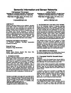
Fig. 5. Operations performed by master and slaves during a cycle of the proposed protocol (in case of three slaves). Decode phase for slave #(n-1) is performed during interrogation of slave #n (R = receive, S = send, D = decode).
4) Slave_Timer: Value of the slave timer when the message was compiled. 5) Link_Quality: Value of the received signal strength indicator (RSSI, range 27–154) given by the IEEE802.11 module. Once again, during the test phase, simplicity has been preferred to safety; no control or error correction/prevention facilities have been introduced. However, this protocol provides a certain degree of flexibility, and improvements can be easily achieved. A general scanning cycle of the proposed wireless system is reported in Fig. 5. The total scanning-cycle duration can be obtained as Ts = Ti · N , where N is the number of slaves in the subnetwork system, and Ti is the interrogation time required to transfer and process the slave related data. In order to reduce the interrogation time Ti, the master sends a request to slave #n, decodes the slave #(n-1) reply then receives slave #n reply. Concurrently on the other side, the slave #n can decode and create its response packet, which will be processed in the next slot. IV. R ESULTS The software has been written in C; UDP/IP stack has been arranged to fit the poor memory resources of the microcontroller, while the Orinoco Silver Card driver has been derived from a free library (Lucent HCF-light). The total occupation is 15 kB of code space and 1 kB of RAM. This is a good result, comparable with code occupancy of simpler systems based on BT or ZigBee. Moreover, it is worth to mention that the remaining resources (more than 50%) of the microcontroller could be used for other tasks, for instance to implement a 32-tap finite impulse response (FIR) filter (800 B ROM, 150 B RAM) for the analog input. The prototype, shown in Fig. 3 and powered with 5 V, absorbs about 350 mA of which 180 mA is due to the Wi-Fi card alone. The prototype is quite inappropriate for battery operation, but it can be used, for instance, on machines with rotating parts; generally, in these cases power supply is available (e.g., through brushes) whereas data cables are the main problem. Time performance of the proposed system, considering both IEEE802.11 complexity and use of a low-cost 8-bit microcontroller, could be critical; therefore, detailed timing experiments have been carried out.
Fig. 6. Distribution of the time required by the prototype to generate and send a packet. One hundred packets have been considered.
Experimental setup for communication tests includes two wireless transducers and one PC (with its own wireless card) connected together with an ad hoc network topology [see Fig. 1(a)]. This configuration has been preferred since it should be a favorable situation to achieve the best performance. Experiments are divided into two groups: In the first one, only two prototypes have been used, one set as the master and the other working as a slave; in the second group of experiments, both prototypes are slaves and they dialog with the PC, where a LabVIEW virtual instrument acts as the master. With the first setup, a point-to-point connection between master and slave has been employed to measure the true rate of Ethernet-packet generation (maximum throughput). Given that the software of master and slave is over our total control with no operating system overhead, an accurate estimation of delays can be done. One hundred consecutive request messages have been generated by the master and received by the slave, which was programmed not to respond: An average time of 2.6 ms is required by the prototype to build and send a packet. Fig. 6 shows its distribution. Transferring a packet from the master microcontroller to the slave microcontroller takes about 1.8 ms. These time intervals have been measured in hardware (with a Logic Analyzer HP1692A connected to the microcontroller) and also verified with a network sniffer, like Ethereal, installed on the PC. Next, the proposed system architecture has been stressed with all its functionalities activated. The PC runs the LabVIEW interface that accesses the sensors, while the Logic Analyzer measures the time delays probing some microcontroller pins. For each transducer, analog input is connected to a waveform generator HP33120 (sine wave at 10 Hz, 4 Vpp); digital inputs are associated to a dip-switch bank, and digital outputs are attached to some LEDs. In this condition, the average value (over 30 measures) of the following time parameters has been computed: 1) ICMP echo request (known as PING) roundtrip delay: Tping = 5.7 ms; 2) time taken for the master to retrieve information from a slave with a single request (no cycle and no overlay) as illustrated in Fig. 7: Td = 11.5 ms; 3) interrogation time as defined above and shown in Fig. 5 (cycling and processing overlay activated): Ti = 9.3 ms. Finally, some experiments about the operative range covered by the prototype have also been carried out. This kind of
FERRARI et al.: IEEE802.11 SENSOR NETWORKING
Fig. 7. Definition of time Td. The master takes the time Td to retrieve information from a single slave, since receive (R) and decode (D) operations have to be executed sequentially.
measurement strongly depends on the environmental conditions: If a level of RSSI equal to 80 is considered as a safe working limit, a 60-m indoor range can be obtained with no obstructions. The presence of metal obstacles or reinforced walls reduces this range down to a half. V. C ONCLUSION In conclusion, a complete solution to connect an IEEE802.11-based sensor with a wireless network has been presented. Wi-Fi is gaining market popularity, and prices of interface cards, chipsets, and other related components are falling. At the same time, vendors of industrial components are moving toward wireless solutions to replace old wired control devices. The proposed-wireless-system architecture can be integrated in an existing Ethernet infrastructure by means of commercial AP, since most diffused protocols are supported (IP and UDP). To show the feasibility, some sensor prototypes have been realized using standard PCMCIA cards interfaced with low-cost electronics. Experimental results demonstrate that the proposed system is compatible with soft real-time (nontimecritical) industrial applications (scanning-cycle duration Ts < 20 ms). Anyway, power consumption is rather high, and the short autonomy of a battery power supply still remains the main disadvantage of the proposed IEEE802.11 sensor system, whose use is suitable only for certain industrial applications, i.e., redundant wireless sensor networks or coupler between different moving parts of a system. R EFERENCES [1] I. Chlamtac, M. Conti, and J. J.-N. Liu, “Mobile ad hoc networking: Imperatives and challenges,” Ad Hoc Netw., vol. 1, no. 1, pp. 13–64, Jul. 2003. [2] Bluetooth SIG, Specification of the Bluetooth System 1.1. (2001). [Online]. Available: www.bluetooth.com [3] IEEE Standard for Information Technology, Telecommunications and Information Exchange Between Systems, Local and Metropolitan Area Networks. Part 11: Wireless LAN Medium Access Control (MAC) and Physical Layer (PHY) Specifications, IEEE Standard 802.11, 1999. [4] IEEE Standard for Information Technology, Part 15.4: Wireless Medium Access Control (MAC) and Physical Layer (PHY) Specifications for LowRate Wireless Personal Area Network, IEEE Standard 802.15.4, 2003. [5] ICHM 20/20, Bluetooth wireless data acquisition module, Oceana Sensor. [Online]. Available: http://www.oceanasensor.com [6] A. Flammini, P. Ferrari, E. Sisinni, D. Marioli, and A. Taroni, “A Bluetooth-based sensor network with web interface,” in Proc. IEEE Instrumentation and Measurement Technology Conf. (IMTC), Vail, CO, May 20–22, 2003, pp. 892–897. [7] C. De Morais Cordeiro, S. Abhyankar, and D. P. Agrawal, “Reducing power consumption and enhancing performance by direct slave-to-slave
619
and group communication in Bluetooth WPANs,” Comput. Netw., vol. 45, no. 2, pp. 119–141, Jun. 5, 2004. [8] Siemens Corp., RLM (Radio Link Module), CP1515 (Wireless Ethernet Card), MOBIC (Mobile Industrial Communicator). [Online]. Available: http://www.ad.siemens.de/imc/index_76.htm [9] A. Flammini, P. Ferrari, E. Sisinni, D. Marioli, and A. Taroni, “Sensor interfaces: From field-bus to Ethernet and Internet,” Sens. Actuators A, Phys., vol. 101, no. 1/2, pp. 194–202, Sep. 2002. [10] P. Ferrari, A. Flammini, D. Marioli, and A. Taroni, “A low-cost Internetenable smart sensor,” in Proc. IEEE Sensors, Orlando, FL, Jun. 12–14, 2002, vol. 2, pp. 1459–1554.
Paolo Ferrari (S’02–A’03–M’04) was born in Brescia, Italy, in 1974. He received the Laurea degree in electronic engineering (with honors) at the University of Brescia in 1999. He received the Ph.D. degree in electronic instrumentation from the same university in 2003. He is currently employed as Researcher with the Department of Electronics and Automation, University of Brescia. His main research activities include signal conditioning and processing for embedded measurement instrumentation, smart sensor, sensor networking, real-time Ethernet, and field-bus applications.
Alessandra Flammini (M’99) was born in Brescia, Italy, in 1960. She received the Laurea degree in physics (with honors) at the University of Rome, Italy, in 1985. From 1985 to 1995, she worked on industrial research and development on digital drive control. From 1995 to 2003, she was a Researcher at the Department of Electronics for Automation, University of Brescia. Since 2002, she has been an Associate Professor at the same university. She teaches several courses about measurements in industrial environments, digital electronics, and microprocessor-based systems. Her main research activity is the design of methods and digital electronic circuits for numeric measurement instrumentation, sensor signal processing, smart sensor networking, and field-bus applications, with particular attention to real-time Ethernet protocols.
Daniele Marioli (M’04) was born in Brescia, Italy, in 1946. He received the Laurea degree in electrical engineering from the University of Pavia, Italy, in 1969. From 1984 to 1989, he was an Associate Professor in applied electronics at Brescia University, and since 1989, he has been a Full Professor of applied electronics at the same university. He was the Director of the Department of Electronics for Automation of the Faculty of Engineering, University of Brescia, from 1993 to 2004. His main field activity is the design and experimentation of analog electronic circuits for the processing of electrical signals from transducers, with particular regard to S/N ratio optimization.
Andrea Taroni (A’04–M’04) was born in Cotignola, Ravenna, Italy, in 1942. He received the Laurea degree in physics from the University of Bologna, Italy, in 1966. He was an Associate Professor at the University of Modena, Italy, from 1971 to 1986. He was the Dean of the Faculty of Engineering of the University of Brescia, from 1993 to 2003. Since 1986, he has been a Full Professor in electrical measurements at the University of Brescia, Italy. Since 2004, he has also been the Director of the Department of Electronics for Automation, Faculty of Engineering of the same university. He has done extensive research in the field of physical quantities sensors and electronic instrumentation, both developing original devices and practical applications.