IFACES: ADAPTATIVE USER INTERFACES FOR AMBIENT INTELLIGENCE Javier Gómez Escribano Universidad Autónoma de Madrid
[email protected]
Germán Montoro Manrique Universidad Autónoma de Madrid
[email protected]
Pablo A. Haya Coll Universidad Autónoma de Madrid
[email protected]
ABSTRACT In this paper we present an ontology language to model an environment and its graphical user interface in the field of ambient intelligence. This language allows a simple definition of the environment and automatically produces its associated interaction interface. The interface dynamically readjusts to the characteristics of the environment and the available devices. Therefore it adapts to the necessities of the people who have to use it and their resources. The system has been developed and tested employing a real ambient intelligence environment. KEYWORDS User interface definition languages, ambient intelligence.
1. INTRODUCTION Ambient intelligence provides “highly interactive environments that use embedded computation to observe and participate in activities that have never previously involved computation” [Coen, M.H. 1998]. In this kind of environments, computers usually keep hidden from users and system services are obtained by means of context awareness interaction. Therefore, rooms, offices, classrooms and homes should be provided with their own entity and improve the quality of life of their inhabitants, helping them in their daily tasks. Moreover, this interaction must be adapted to the task, the environment, its occupants (with their specific characteristics and special necessities), and the available resources [Paterno, F., and Santoro, C. 2002; Rayner, M. et al. 2001]. These environments provide new possibilities of interaction [Weiser, M. 1994], offering new challenges to the designers of the interfaces [Shafer, S., et al. 2001]. This interaction could be in many different ways, with a mouse/keyboard in a PC, mobile devices [Eisenstein, J., et al. 2000], oral interactions [Haya, P.A., and Montoro, G. 2006], etc. In this paper we present the results in the process of definition and implementation of a Graphical User Interface (GUI) for intelligent environments that adapts to the domain of each environment. This research is based on a real intelligent environment. This environment is formed by a laboratory furnished as a living room, provided with several devices. Among them, we can find lights and switches, an electronic lock mechanism, speakers, microphones, a radio tuner, a TV set, RFID cards, etc. We have defined an ontology language to describe the environment. The ontology is formed by two parts, one describing the environment in general, and the other one describing the representation of the environment. Then, the system merges this information, so that users can easily access to the information.
GUIs are automatically generated from the information in the ontology and dynamically adapt to the device (i.e. to screen resolution), their purpose is to ease the interaction with the environment and control devices. The paper is organized as follows. In section 2 we provide an overview of other languages to describe ontologies and GUI. In Section 3 we present the implemented system: “AmIGO” and it extension: “iFaces” in Section 4. Then, in Section 5, an application in a real environment is presented. Finally, we conclude in Section 6.
2. RELATED WORK 2.1 Ontologies One of the most popular languages employed to define ontologies is Web Ontology Language (OWL) [Smith, et al. 2004.], which is a formal recommendation of the World Wide Web Consortium (W3C). OWL is intended to be used when the information in the documents is going to be processed by the applications, i.e. a web browser. There are three sublanguages, Lite, DL and Full. Although it is used in some others ambient intelligence projects, such as MIMUS [Pérez, G., et al. 2006a] and Delfos [Pérez, G. et al. 2006b], OWL is verbose and it is web-oriented. This makes it not very suitable for a straightforward description of an environment and its interfaces, which is one of the main requisites of our project. Another recommendation from the W3C is Resource Description Framework (RDF) [Beckett, D. and McBride, B. 2004], which was originally a meta-data model but which has come to be used as a general method of modeling information. It uses statements to define resources, in the form subject – predicate – object expressions. A collection of these statements is an ontology. Its drawbacks are: its XML syntax is too verbose, the statement notation (subject – predicate – object) is not expressive enough and its ability to reify statements is handled ambiguously. To develop our ontology, we have to decide the representation mechanism which allows us to model the state of a single entity and also the environment. Some of these mechanisms are [Chen, G., and Kotz, D. 2005; Strang, T., and Linnhoff – Popien, C. 2004]: – Key–Value: The contextual information is represented as a set of pairs variable name (or key) and value. – Mark–up Languages: It uses a semi–structured data model in a language similar to XML. Another example could be Composite Capabilities/Preferences Profile, from the W3C [Klyne G., et al. 2004] and User Agent Profile (UAProf) [Nilsson, M. 2002], used by the Open Mobile Alliance (OMA) Consortium. – Tuples: It is a group of values each of a specified type. In example, tuples were used as the basic interchange unit in the generative communication mechanism, proposed by Gelernter [Gelernter, D. 1985]. This model has been used in projects as One.World [Grimm, D. 2004] and Gaia [Román M., and Campbell, H. 2000]. – Entity–Relation Model: This model is used in the Entity–Relation (ER) paradigm of data bases. Other models are derivated from ER, in example, a graphical extension of ORM (Object – Role Modeling) which models contextual information. Another example which combines the object oriented model and ER model is Object Model (OM). – Object Oriented Model: The context processing details and the access to it is encased in objects. Both, ORM and OM, have simility with the Object Oriented Model (OOM) but they are oriented to ER Model. The Active Object Model (AOM) only uses the object oriented paradigm. It was introduced in GUIDE project [Cheverst, K., et al. 2000]. – Logic Model: The context is represented as a group of facts and rules which are described using first order predicated logic. – Ontology Based Model: This model is based in a hierarchy categorization of the context. This paradigm has been used in representing contextual information and in ubiquitous computation.
The data model we propose is a representation of information relative to the world, regardless of the source and the abstraction level. The most suitable models to represent a context are Object and Ontology models [Strang, T., and Linnhoff– Popien, C. 2004]. Both divide classes and instances, where classes are organized hierarchically and each instance belongs to a class of the hierarchy. Object Oriented Models encase algorithm part inside the objects. On the other hand, ontologies focus on defining data.
2.2 User Interfaces / UIDL To define UIs, User Interface Description Languages (UIDLs) are commonly employed. Some of them are UIML, XIML and USIXML. User Interface Markup Language (UIML) is an XML-based language whose goal is to express user interfaces for multiple software platforms on different devices and for multiple applications [Phanouriou, C. 2000]. The latest draft specification is UIML 3.1, which refines previous versions and adds support for dynamic and multimodal user interfaces. As a XML derivation it is verbose, and it is complicated to modify an interface, in case of a non-programmer person. eXtensible Interface Markup Language (XIML) [Puerta, A., and Eisenstein, A. 2002] is a common representation for interaction data. It was created to fulfill some common requirements of UIDLs, such as being able to relate the abstract and the concrete data of an interface, enabling knowledge–based systems to exploit the captured data, etc. It allows adaptation to desktop or PDA interfaces but it needs an “intermediate” presentation component with predefined relations to these controllers, so it only provides some degree of automated mapping [Trewin, X.S., et al. 2003]. User interface eXtesible Markup Language (UsiXML) [Vanderdonckt, J., et al. 2007] allows programmers to describe multimodal user interfaces, with different interaction modalities and, that interfaces, could be shown in many different platforms and devices. It describes, in a high abstraction level, the elements of an interface and the interaction modalities also. UsiXML is intended for non-developers, such as analysts, specifiers, designers, human factors experts, project leaders, novice programmers, so a basic formation in user interfaces is required. However, such approaches have usually focused on providing support, not in the runtime phase, but only in the design and authoring phase in order to help designers to efficiently obtain different versions that adapt to the various interaction features. All of them are languages to describe UIs. An example of a Framework to create UIs is SUPPLE [Gajos, K., and Weld, D.S. 2004] which is an application and device – independent system, that automatically generates user interfaces for a wide variety of display devices. SUPPLE uses decision-theoretic optimization to render an interface from an abstract functional specification and an interchangeable device model. SUPPLE can use information from the user model to automatically adapt user interfaces to different tasks and work styles while also providing extensive customization mechanisms that allow for modifications to the appearance, organization and navigational structure of the user interface. This has a big inconvenient, since you must be a programmer to create the UI.
3. AMIGO: AN ONTOLOGY FOR AMBIENT INTELLIGENCE AmIGO is the acronym of “Ambient Intelligence General Ontology”. This is an ontology description language that defines the characteristics of an intelligent environment, the devices that are in it, their properties, capabilities and relations. To develop AmIGO we have chosen an ontology model that allows a representation of information relative to the world, regardless of the source and the abstraction level. The representation of the information includes mechanisms to be able to describe the elements in the environment. The data model is formed by two clearly different parts, but strongly related. On the one hand, a meta-language is required to define the characteristics and relations of the objects that can exist in the environment; on the other hand, a language is needed to describe each object that, in a given moment, is associated to the environment.
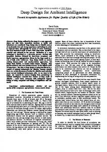
The first part is the model schema (see Figure 1). Its main elements are classes, which represent the different possible categories of the real world. The second part is formed by the realizations of these classes, which are instances. class [abstract] [extends ] [“{ ” [ must property prop ] [ may property prop ] [ must – list ] [ may – list ] [ cap – list ] “} ”] must – list = must properties “{” prop – list “}” may – list = may properties “{” prop – list “}” prop – list = name [“;” prop – list] name = identifier [ dv value ] cap – list = capability [ cap – list ]
Figure 1. Example: Syntax for class definition
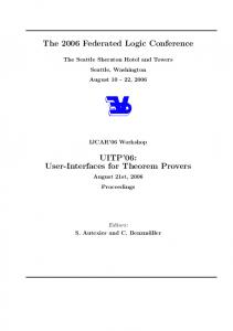
Each class is formed by: – Name: That is a unique identifier. – Type: The category of the reality where it belongs. – Properties: A set of name-value pairs that models its intrinsic characteristics. Each property has a type that can be “Numeric”, “String”, “Boolean”, etc. Properties can be “must properties” which are the properties that are considered to have always a value and “may properties” which are the ones that are optional. – Relations: A connection with another class. A class can have more than one relation with the same name, but the class that is related to must be different. A class cannot have a relation with itself. – Capabilities: They represent an ability that a class has to perform a task or an action. Since GUIs are based on the actions that elements can perform in an environment, capabilities are a key issue in their development (See Section 4). One example is the capability “isSwitchable” which has a property called “status” that represents the physical state of the device (See Figure 2). capability isSwitchable { must properties { status; } }
Figure 2. Example: Definition of the capability “isSwitchable” This schema includes a specialization mechanism using simple inheritance. Therefore, a class inherits all the properties and capabilities from another class. The inherited class is called “offspring class”, and the class when it is inherited from is called “parent class”. An offspring class can only have one parent, but a parent class can have many offspring classes. An example of a class and its properties and capabilities is given in Figure 3. The class “light” has a property called “name”, with its default value set to “Table Light” and the capability “isSwitchable” (defined in Figure 2). An instance of a class gets the properties and capabilities from its type of class, although they could be changed to its own if necessary. To model a new environment it would only be necessary to specify the entities (this is, the realizations of the classes) that compose the environment and the relations between them. The communication mechanism used is a blackboard model, which is a middleware between “real world”, UIs and applications [Haya, P.A., et al. 2004]. The blackboard stores all the data from the real world devices. This provides coordination between the applications that interact with the environment, because they
don’t have to be synchronized either in time or space. It is very useful for the reconfiguration of dynamic environments, since components appear and disappear clearly for the applications. class light extends actuator { must property name dv “Table light”; capability isSwitchable; }
Figure 3. Example: A class definition
4. IFACES: AN EXTENSION OF AMIGO FOR USER INTERFACES iFaces (a contraction of interfaces) is an extension of AmIGO that has all the information referred to the representation of the elements of the environments for the GUI. Interfaces are generated automatically because the ontology has the representation properties of an interface and their default values. They can be changed, to make the interface adapt to the user preferences. Since UIs are based on the actions that elements can perform in an environment, the set of representation objects is fixed by the capabilities that a class has. The capabilities are associated to the classes and the same capability can be associated to several classes. The property of a capability has three default attributes: “iFaceType” (interface type), which defines the representation object for the property, “iName” (interface name), which is a name to identify the representation object and “iText” (interface text), which contains information relative to the text that has to be shown for each different possible state of the representation object. The representation objects can be buttons, sliders and spinners, lists, check boxes, colored boxes, text boxes and dynamic and static frames. Every class has also some default properties. One of them is the property “iIcon” (interface icon), which specifies the corresponding graphical icon for that class. Classes can also have an “iName” property that is a descriptive name of the class and is used as a title of the group of class’ objects. These are optional properties; if users don’t specify an icon, the interface would employ a standard image, and the class name would be used for the title. class light extends actuator { must property name dv “Table light”; may properties { iIcon dv “icon.jpg”; iName dv “Living ceiling light”; } capability isSwitchable:status:representation:graphics { must properties { iFaceType dv “Button”; iName dv “Status”; iText dv “Turn ON&Turn OFF”; } } }
Figure 4. Representation of a class “light” and the graphical objects that it generates For example, from the descriptions in Figures 2 and 3, is very easy to define a class light (See Figure 4) with the graphical icon “icon.jpg”. Besides, the property “status” of its capability “isSwitchable” is represented graphically by a “Button”. The title employed in the graphical representation of this Button
would be “Status” and the text for its possible states “Turn ON” and “Turn OFF”. The title of the group of objects is “Living ceiling light”, as it defined in “iName” property. Since classes and their representation are already defined, a new interface would be generated only by specifying the entities that compose the environment. That representation would take the default values for its representation objects, so no programming knowledge is required. Just in the case the user wanted to customize the interface it would be necessary that she would have some knowledge about the ontology and interface description languages.
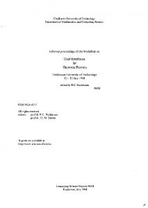
5. APPLICATION IN A REAL WORLD ENVIRONMENT To develop and test the application, we have used the description languages defined in Sections 3 and 4 with a real ambient intelligence environment. It is composed by lights and switches, an electronic lock mechanism, speakers, microphones, a radio tuner, a TV set, RFID cards, etc. (Figure 5).
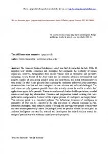
Figure 5. Screenshot of the environment After defining the instances of the classes, the interface is automatically generated. The information represented in the interface corresponds with the elements modeled in the ontology. Their disposition dynamically adapt to the screen resolution of the device to provide a clear view of all the elements in the environment. An example of the generated interface for this environment can be seen in Figure 6. This makes possible to use the interface in a PDA, a desktop computer or any other available device. If the user changes the size of the window or the resolution of the screen the size and disposition of the elements of the interface automatically adjust to the new situation. For instance enlarging the interface window automatically increases the size of its elements, adapting them to everyone necessities.
Figure 6. Example of an automatically created graphical user interface
6. CONCLUSIONS AND FUTURE WORK In this paper we have presented a language for describing an ambient intelligence environment and its components, as well as their representation in a graphical user interface. Since OWL is verbose and web–oriented, makes it not very suitable for a straightforward description of an environment and its interfaces, which is one of the main requisites of our project. In Section 2.2 some UIDLs were presented. They are XML – based languages. From our point of view, XML is not suitable as a high-level language. Yet XML is desirable for application interoperatibility, describing or personalizing a complex interface could be a difficult issue for a programmer. That is one of the reasons why we decided to choose a non XML-based language. Defining the GUI is a straightforward task. Naming the components in the environment and their types would be enough to automatically create the interface, because the default representation is already predefined. Just in the case the user wanted to customize it she would need to have knowledge about the ontology description language. Therefore, the created GUIs fulfill the following requisites: – They are defined in a simple way, making them easy to reconfigure and implement in different environments, and even by people without specific technical knowledge. – They dynamically adapt to the particular characteristics of the available devices, and therefore to the people who have to use it. These interfaces have been developed and tested in a real ambient intelligence environment. For future work the GUIs would need to be able to reconfigure dynamically in runtime. A graphical tool would also help to manage the ontological information more easily.
ACKNOWLEDGEMENT This work has been partly funded by HADA project number TIN2007 – 64718 and the UAM – Indra Chair in Ambient Intelligence.
REFERENCES Beckett, D. and McBride, B. 2004. RDF/XML Syntax Specification (Revised) W3C Recommendation, 10 February 2004 Chen, G., and Kotz, D. 2005. Policy-Driven Data Dissemination for Context-Aware Applications. Pervasive Computing and Communications, 2005. PerCom 2005. Third IEEE International Conference on Publication. 8-12 March 2005 Cheverst, K., et al. 2000. Experiences of Developing and Deploying a Context–Aware Tourist Guide: The GUIDE Project. Proceedings of the 6th annual international conference on Mobile computing and networking. Boston, Massachusetts. Coen, M.H. 1998. Design Principles for Intelligent Environments. Proceedings of the AAAI Spring Symposium on Intelligent Environments (AAAI98). Eisenstein, J., et al. 2000. Adapting to mobile contexts with user – interface modelling. Workshop on Mobile Computing Systems and Applications, Monterey, CA, 2000. Gajos, K., and Weld, D.S. 2004. SUPPLE: Automatically Generating User Interfaces. Proceedings of IUI’04. Funchal, Portugal, 2004. Gelernter, D. 1985. Generative communication in Linda. ACM Transactions on Programming Languages and Systems (TOPLAS), January 1985 Grimm, D. 2004. One.world: Experiences with a Pervasive Computing Architecture. Pervasive Computing, IEEE Publication Date: July-Sept. 2004 Haya, P. A., Montoro, G., and Alamán, X. A prototype of a context – based architecture for intelligent home environments. International Conference on Cooperative Information Systems (CoopIS 2004), Larnaca, Cyprus. October 25 – 29, 2004. Haya, P. A., and Montoro, G. A spoken interface based on the contextual modelling of smart homes. HCI related papers of Interacción 2004, Raquel Navarro – Prieto and Jess Lors – Vidal, Eds. Springer Verlag. ISBN: 1-4020-4204-3. January, 2006. Klyne G., et al. 2004. Composite Capability/Preference Profiles (CC/PP): Structure and Vocabularies 1.0. W3C Recommendation, 15 January 2004 Nilsson, M. 2002. UAProf. An overview. W3C Delivery Context Workshop, 4/5 March 2002. Paterno, F., and Santoro, C. 2002. One Model Many Interfaces. Proceedings of CADUI, 2002. Pérez, G. et al. 2006b. Integrating OWL Ontologies with a Dialogue Manager. SEPLN Magazine, Vol. 37 (2006) Pag. 153 – 160 Pérez, G., et al. 2006a. A multimodal architecture for home control by disabled users Spoken Language Technology Workshop, 2006. IEEE, Pag. 134 – 137 Phanouriou, C. 2000. UIML: A Device – Independent User Interface Markup Language. PhD Thesis. Puerta, A., and Eisenstein, A. 2002. XIML: A Universal Language for User Interfaces. XIML White paper Rayner, M. et al. 2001. Plug and Play Speech Understanding. 2nd SIGdial Workshop on Discourse and Dialogue, September 2001. Román M., and Campbell, H. 2000. Gaia: Enabling Active Spaces. Proceeding of 9th ACM SIGOPS European Workshop, September 17th-20th, 2000. Kolding, Denmark, pp. 229-234. Shafer, S., et al. 2001. Interaction Issues in Context – Aware Intelligent Environments. Human – Computer Interaction, 16, Pag. 363 – 378, 2001. Smith, et al. 2004. OWL Web Ontology Language Guide Editors W3C Recommendation, 10 February 2004 Strang, T., and Linnhoff – Popien, C. 2004. A Context Modeling Survey. UbiComp 1st International Workshop on Advanced Context Modelling, Reasoning and Management, Nottingham (2004) Pag. 34 – 41 Trewin, X.S., et al. 2003. Abstract user interface representations: how well do they support universal access? Proceedings of the ACM Conference on Universal usability. 2003 Vanderdonckt, J., et al. 2007. Distributed User Interfaces in Ambient Environment. Proc. of AmI – 07 Workshop on “Model Driven Software Engineering for Ambient Intelligence Applications” MDA – AMI07 (Darmstadt, November 7 – 10, 2007), Lecture Notes in Computer Science, Springer – Verlag, Berlin, 2007, Pag. 44 – 52 Weiser, M. 1994. The world is not a desktop. ACM Interactions, 1, 1, Pag. 7 – 8, 1994.