A Fully Integrated Hybrid Silicon AWG Based Multiwavelength Laser Geza Kurczveil, Martijn J.R. Heck, Jonathan D. Peters, John Garcia, John E. Bowers University of California Santa Barbara, ECE Department, CA 93106, USA E-mail:
[email protected]
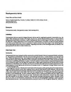
Abstract For the first time, a fully integrated hybrid silicon AWG based multiwavelength laser on SOI is presented. Four-channel operation with 360 GHz spacing and 25-35 dB SMSR is shown. I. Introduction For wavelength division multiplexing (WDM) applications, laser sources with multiple wavelengths are of great interest. Arrayed waveguide grating (AWG) based multiwavelength lasers (MWL) have been demonstrated by Den Besten et al. [1] among others on InP. AWG based MWLs are interesting because they are easier to fabricate than those based on diffraction gratings [2]. Making such devices on a CMOS compatible platform would reduce the cost and the passive losses of these devices while also increasing the yield [3]. In this work, we present an AWG based MWL on an SOI substrate. This is the first time an AWG was integrated with active devices on the hybrid silicon platform. II. Device Design and Fabrication The AWG laser was fabricated on the hybrid silicon platform as outlined in Reference [4]. The waveguides and the AWG were defined in a single etch step on an SOI wafer with 0.7 μm top silicon and 1 μm thick buried oxide layer. In the passive region, where no III-V remains on the silicon at the end of the process, the rib waveguide is 2 μm wide and the rib etch is 0.44 μm. In the hybrid (SOA) region, the width is 1 μm to increase the confinement of the optical mode in the quantum wells as shown in Reference [4]. Multilevel tapers between hybrid and passive sections similar to those in Reference [5] are used to minimize reflections and transition losses. The device layout is illustrated in Figure 1(a). It consists of 4 hybrid silicon SOAs that act as gain media in the 4 separate channels of the AWG. By biasing the amplifiers SOA1 – SOA4 above threshold, four lasing cavities are formed between the facets f1 – f4 and the common facet on the right respectively. The AWG acts as a bandpass filter and determines the lasing wavelength. Figure 1(b) is an optical photograph of the processed device. An optical microscope picture of the AWG before III-V processing is shown in Figure 1(c).
Figure 1: (a) Schematic diagram of the hybrid silicon MWL. (b) Optical image of the fabricated device showing two separate MWLs. c) Optical image of the AWG before III-V processing.
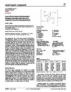
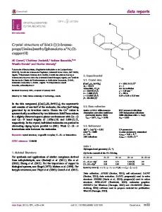
III. Experimental Results A passive AWG with the same design and from the same process run was characterized using an external ASE source. The transmission spectrum is shown in Figure 2(a) by solid lines. The channel spacing is 2.9 nm and the insertion loss ranges from 3 dB to 4 dB. The crosstalk is 9.4 dB on average - in good agreement with design parameters because of the limited number of arms in the AWG (see Fig. 1(c)). The transmission spectrum of the finished device is shown in Figure 2(b) with dotted lines. The spectrum degraded (higher crosstalk, flatter passbands) as etch steps in the III-V process attacked the AWG and introduced significant phase errors. The lasing spectrum optimized for high sidemode suppression ratios (SMSRs) is shown in Figure 2 (b). The SMSR is between 25 and 35 dB. A narrower AWG passband should increase the SMSR. The L-I curves for the 4 channels are shown in Figure 3(a). Channels 2-4 have threshold currents of 113-120 mA. The higher lasing threshold and the lower output power of Channel 1 are
due to the lower AWG peak transmission as shown in Figure 2(a). Thus SOA1 has to be operated at a higher gain to overcome these higher losses.
Figure 2: (a) Transmission spectrum of the MWL-AWG (dotted lines) below threshold. The spectrum of a similar reference AWG before III/V processing is also shown (solid lines). The vertical axis on the right represents the output power at an SOA bias of 75 mA. (b) Lasing spectra optimized for high SMSR.
Figure 3(b) shows a contour plot of the optical spectrum as a function of current for Channel 2. Mode hopping and multimoding is observed and they are present in all channels. This is attributed to the flattened passbands of the AWG, which result from damage to the AWG during processing and can be eliminated with proper passivation. Direct modulation of the device showed 10%-90% rise and fall times as low as 190 ps and 240±8 ps respectively, indicating that this device could also be used as a fast tunable laser. However wavelength stability during switch-on can be an issue and requires further investigation.
Figure 3: (a) L-I curves for the 4 channels, measured at the common output facet. (b) Contour plot showing the lasing wavelength of Channel 2 as a function of drive current. The color scale is in dBm/0.06nm.
IV. Conclusion The first fully integrated hybrid silicon MWL based on an AWG is presented. This fast tunable source should be useful for WDM systems and optical interconnects on and off chip. The performance of this device should be improved by protecting the AWG during III-V processing, resulting in lower thresholds and larger SMSR. V. Acknowledgment: This work was supported by DARPA/MTO under award W911NF-04-90001. VI. References [1] J. H. Den Besten et al., “An Integrated 4x4-Channel Multiwavelength Laser on InP”, IEEE Photonics Technology Letters, 15, 3, p. 368-370, 2003 [2] M.R. Amerfoort et al., “Compact arrayed waveguide grating multifrequency laser using bulk active material”, Electronics Letters, 33, 25, p. 2124-2126, 2007 [3] G. Roelkens et al., “Laser emission and photodetection in an InP/InGaAsP layer integrated on and coupled to a Silicon-on-Insulator waveguide circuit”, Optics Express, 14, 18, p. 8154, 2006 [4] H. Park et al., “Photonic Integration on the Hybrid Silicon Evanescent Device Platform”, Advances in Optical Technologies, Article ID: 682978, 2008 [5] H. Park, Dissertation, UCSB 2008