ILP formulation of Signal Power Based Routing for. Single and Multilayer Optical Networks. Marcell Perényi, Szilárd Zsigmond and Tibor Cinklerâ . Department of ...
ILP formulation of Signal Power Based Routing for Single and Multilayer Optical Networks Marcell Perényi, Szilárd Zsigmond and Tibor Cinkler† Department of Telecommunication and Media Informatics Budapest University of Technology and Economics Budapest, Hungary {perenyim, zsigmond, cinkler}@tmit.bme.hu Abstract – In† both metropolitan optical networks (MON) and long haul optical networks (LHON) the signal quality is often influenced by the physical impairments, therefore a proper impairment based routing decision is needed. In this paper we propose new routing and wavelength assignment (RWA) methods where the control plane has influence on the signal power of the Wavelength Division Multiplexed (WDM) channels. Nowadays in nearly all kinds of reconfigurable optical add-drop multiplexers (ROADM) the signal power can be tuned via variable optical attenuators (VOA) from the control plane. We give the exact integer linear programming (ILP) formulation of the method for both single and multilayer networks. In the first case we assume that no signal regeneration is allowed along the path, while in the more complex multilayer case 3R signal regeneration, grooming and wavelength conversion can all be done in the electronic layer. The proposed algorithm can be used in existing WDM optical networks where the nodes support signal power tuning. The algorithm finds the global optimum, if it exists, for a certain network topology, physical constraints and demand set. Keywords optimization
–
routing,
I.
signal
power,
WDM,
cross-layer
INTRODUCTION
The tremendous growth in broadband communication services leading to the huge expansion of the Internet has triggered an unprecedented demand for bandwidth in telecommunication networks. Multi-wavelength technology appeared as the solution for the bandwidth hungry applications and WDM has been introduced to increase the transmission capacity of existing optical links. It has been soon recognized that the switching decision can be made according to the incoming wavelength without any processing of the data stream. In single hop WDM based All Optical Networks (AON) a wavelength is assigned to a connection in such a way that every connection is handled in the optical domain without any electrical conversion during the transmission [1], [2]. The WDM networks have successfully solved the capacity issues, but the continuously changing traffic still causes serious problem for the operators. Emerging demands often cannot be satisfied without modifying the network design (that is quite costly and difficult), so operators try to avoid this situation whenever possible. There is a strong need for a system that can †
The work described in this paper has been supported by the FP7 Network of Excellence BONE funded by the European Commission.
deliver the same capacity as WDM, with the design and provisioning flexibility of SONET/SDH. The solution must ensure flexibility for dynamically changing future demands. The reconfigurable optical network offers the possibility to increase or change services between sites with no advanced engineering or planning, and without disrupting existing services. In the past, reconfigurable optical networking technology was too expensive or delicate to be widely deployed. With recently matured silicon-based integrated Planar Lightwave Circuit components, reconfigurable optical add/drop multiplexers (ROADMs) are now being installed by many operators. The technology called ROADM represents a real breakthrough for WDM networks by providing the flexibility and functionality required in present complex networking environments. Older, or fixed, OADMs cannot configure capacity at a node without manual reconfiguration and typically support reconfiguration of only a limited number of wavelengths. In contrast, ROADMs allow service providers to reconfigure add and drop capacity at a node remotely, reducing operating expenses by eliminating the time and complexity involved in manual reconfiguration. ROADM by itself is not enough. Increased data management capabilities on individual wavelengths are also needed to exploit the benefits of ROADM in metro and backbone WDM networks. For instance, ROADM rings are very sensitive to topology changes and need strict monitoring and control of wavelength power to keep the system in balance. The real innovation lies in the system engineering related to the ROADM function, addressing per-wavelength power measurement and management, and per-wavelength fault isolation. Almost every optical system vendor has commercial ROADM with wavelength monitoring functions (see e.g. [3][6]). The next step towards a fully reconfigurable WDM optical network is the deployment of tunable Small Form-factor Pluggable (SFP) interfaces, where the wavelength allocation is modified according to the network changes. The tunable dispersion compensation elements mean another innovation. Nowadays these ready-made products can be purchase [7], [8]. The evolution of optical networks seems to tend towards a fully reconfigurable network where the control and the management plane (CP and MP) have new functions, such as determining the signal quality, tuning the wavelength frequency, setting dispersion compensation units, and – by using variable optical
In this paper we propose a new ILP based RWA algorithm where the control plane handles the routing and the signal power allocation jointly. Nowadays in nearly all types of ROADMs the signal power can be tuned with variable optical attenuators (VOA) from the management system. The proposed method can be used in existing WDM optical networks where the nodes support signal power tuning. The method also finds global optimum if it exists. The rest of the paper is organized as follows: in Section II we overview physical considerations, including current practices for setting channel powers, proof of physical feasibility, and relation between channel power and spanned distance. Section III presents the applied network model. Section IV and Section V introduce our novel ILP formulations of signal power based routing for single and multi layer optical networks, respectively. Section VI shows the benefits of the algorithm, while Section VII concludes the paper. II.
PHYISICAL CONSIDERATIONS
Currently the power of certain channels within a fiber is set to equal levels. This is one of the remaining practices of pointto-point optical networks. Naturally using this kind of channel power allocation is a technical simplification. The other reason for using the same channel powers is the nonlinear effects which in this case have the smallest impact on the signal quality [11-17]. Our idea is to use different channel powers according to the length of the path of the connection request to fulfill the optical signal to noise ratio (OSNR) to achieve biterror free detection. E.g. for a long distance connection we can increase the signal power of the dedicated wavelength, while for a short distance connection lower wavelength power is satisfactory. Due to the nonlinear effects there is an upper bound on the totally inserted optical power in one fiber, which has to be observed. Consequently, if we increase the signal power of one channel, the signal powers of other channels in the same optical fiber have to be decreased. In recent years there have been some publications which apply the same idea of different channel power allocation. This problem was considered in [18]-[20]. In [18] a general OSNR network model was developed and the OSNR optimization problem was formulated as a non-cooperative game between channels. A distributed iterative algorithm was also proposed. A. Physical feasibility As mentioned before, our proposed algorithms use different channel powers in the same optical fiber. This approach introduces many new problems related to physical feasibility. All physical effects were already investigated using equal channel power allocation. The only difference in our case is that the impacts of the effects are different for each channel,
since the signal powers are different. In case of linear effects the signal power has no influence on the dispersion and its compensation schemes. The only linear effect which has signal power dependency is the crosstalk in the nodes. We assume that using the well-known power budget design process the effects of the crosstalk can be eliminated. 3,5 3,0
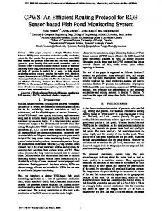
Signal Power (mW)
attenuators – setting the channel powers. Of course traditional functions (such as routing) remain the main function of the CP and MP. Routing and Wavelength Assignment (RWA) plays a central role in the control and management of optical networks. Many excellent papers deal with the design, configuration, and optimization of WDM networks (see e.g. [9-10]). However, they do not consider the physical parameters of the fully reconfigurable optical network in the RWA method at all.
3,4 (mW) Adaptive Ch7 1,6 (mW) Adaptive Ch4 0,4 (mW) Adaptive Ch2 1,6 (mW) Equal Ch2 1,6 (mW) Equal Ch4 1,6 (mW) Equal Ch7
2,5 2,0 1,5 1,0 0,5 0,0
0
2
4
6
8
10
12
14
16
18
20
22
Hop Number
Figure 1. Signal power dependency from the number of EDFAs in chain
More interesting question is how the Erbium Doped Fiber Amplifiers (EDFAs) react to the use of different channel power allocations. For this purpose we made simulations using the VPI TMM/CM Version 7.5 simulation tool [21]. We assumed a system with 8 channels which are multiplexed and then amplified using EDFA rate propagation modules. We aimed to investigate the difference between the uniform and the adaptive channel power allocations. Following the amplifier an attenuator was placed with attenuation equal to the gain of the EDFA. The results can be seen in Figure 1. On the horizontal axis the number of hops is plotted, i.e., the number of EDFAs and attenuators connected in a chain. On the vertical axis the “powers of ones” (the power of the signal level of one) is plotted, where the “power of ones” is the power in case the transmitter is switched on. The first three curves represent the adaptive channel power allocation where the “powers of ones” are set to 0.4 mW, 3.4 mW and 1.6 mW, for channel two, seven and all other channels, respectively. We use these values because applying adaptive signal power routing on the COST 266 topology these values are the maximum, minimum and average channel powers, respectively. We plotted the values for channel two, four and seven. As it was expected, if the number of hops increases, after a certain number of inline amplifiers “the power of ones” decreases, i.e., the signal quality becomes very poor. The interesting thing is that if the number of consecutive amplifiers is lower than this value, “the power of ones” remains nearly the same. Because of this behavior the EDFA supports adaptive signal allocation. To compare the performance of the two power allocation schemes we made exactly the same simulations as it was described formerly but without allowing different channel powers. In this case for all channels (channel 2, 4 and 7) the “powers of ones” were set to the same value (1.6 mW). See the last three curves in Figure 1. It can be seen that the three curves are very close to each other. The only difference is due to the wavelength dependency of the EDFA. It is interesting that the results obtained for adaptive
and uniform allocation schemes are nearly the same. Difference can be seen only for high numbers of hops, where the signal quality is very poor. These results lead us to the conclusion that the so far deployed EDFAs behave similarly in case of both uniform and non-uniform channel power allocations in a single optical fiber. The other interesting question is about the nonlinear effects, since these effects highly depend on the used signal powers. The only solution is to limit the signal power inserted in one optical fiber. This must be done in both allocation schemes. Another problem is the maximum allowed difference between the maximum and the minimum channel powers. In our case this is an input parameter of the algorithm. Determining this value is a hard task and is out of the scope of this paper. Finally to conclude: according to the results adaptive signal power allocation scheme can be implemented in optical systems deployed so far. Moreover, the authors know existing WDM optical networks operating without any error, where different channel powers – though not intentionally – are used, since the power tuning was not performed for the inserted channels in the OADMs. B. Relation between channel power and maximum allowed distance To investigate the relation between the signal power and the maximum allowed distance, we consider a noise limited system where other physical effects can be taken into account as power-penalty:
⎛ ⎞ ⎛ B0 ⎞ ⎜ 20⋅logQ −10⋅log ⎜ B ⎟ −58+ΓdB + NF+ M ⎟ e⎠ ⎝ ⎜ ⎟ 10 ⎜ ⎟ ⎜ ⎟ ⎝ ⎠
Lc = 1/10 (2.5) For typical constant values used in telecommunications the Lc is between 500 and 2000. The effects of an optical node on the signal quality are similar to the impact of an about 90 km long optical fiber, since it has nearly the same attenuation. Using the approximation mentioned previously in the routing algorithm, when the physical effects are taken into consideration, we substituted each node with a 90 km optical fiber. Naturally, more accurate models [23], [24] can be implemented for characterizing the networks. III.
NETWORK AND ROUTING MODEL
We applied the wavelength graph (WL graph) modeling technique. The WL graph (which can be regarded as a detailed virtual representation of the network) is derived from the physical network considering the topology and the switching capabilities of the devices (nodes). The technique allows arbitrary mesh topologies, different types of nodes and joint optimization of multiple layers. A simpler version of the model has been first proposed in [25]. Demand 1st Wavelength 2nd Wavelength
Electrical layer ROADM so
Considering a chain of amplifier the OSNR of the end point can be calculated as follows [22]:
OSNR dB =58 + Pin − Γ ( dB ) − NFdB − 10 ⋅ log N − M (2.1) where noise figure (NF) is the same for every amplifier and the span loss (Γ(dB)) is the same for every span. Pin is the input power in dBm, M is the margin for other physical effects, and N is the number of spans. We assume that there is an inline amplifier in every l km. This means that if the length of the link is L, N is ⎣⎢ L / l ⎦⎥ , i.e. the integer part of the division.
1. . .
W
λ1
V -›i
lenPhyNode
yomn= 0 m
Demand o
n
i r
λ2 Demand k
Optical layer
yoij = 1
pkrt
o
p
j t PhyLink
ij
λ1 λ2
Having into mind that
⎛B ⎞ Q dB =OSNR dB + 10 ⋅ log ⎜ 0 ⎟ ⎝ Be ⎠
(2.2)
where B0 is the optical bandwidth and Be is the electronic (digital) bandwidth of the receiver. The logarithmic QdB and the linear Q have the following relation:
QdB =20 ⋅ log ( Q )
(2.3)
Substituting equation (2.2) and (2.3) into (2.1) we obtain the linear relation between the maximum allowable distance and the signal power.
L = L c ⋅ PmW
(2.4) where PmW is the input power in mW, L is the maximum allowable distance, and Lc is the linear factor between them.
Figure 2. Model of switching device with optical and electronical switching capabilites, grooming and 3R regeneration (in the electronic layer)
The model of an ROADM switching device assumed in our simulations is shown in Figure 2. The device can perform optical switching and – through the electronic layer – wavelength conversation, grooming and 3R signal regeneration. The device illustrated in Figure 2 has an input and an output interface with one physical link (or fiber) connected to each. Each physical interface supports two wavelengths (W=2), marked by blue dashed and red solid lines. The signal powers of the wavelengths in the right hand side physical link are different, pijo and p krt – as shown by the small subfigure. The example also comprises two demands (indicated by dash-dotted line): demand k passes though the switch in the optics, while demand o originates in this device, in the electronic layer (so). A certain length of fiber (lenPhyNode) is assigned to each internal edge, e.g., edge (n, i), which
corresponds to the amount of signal distortion that the switching functionality introduces in the demand path. The edges representing O/E or E/O conversion are shown by grey color.
(2.9) L c = 1200 Constant Lc is the factor of the linear relation between the input power of a demand (in mW) and the maximum distance the signal is allowed to reach.
In the routing we assume that WL conversion, grooming and signal regeneration are possible only in the electronic layer, and that the noise and the signal distortion accumulate along the lightpath. Actually, re-amplification, re-shaping, and retiming – which are collectively known as 3R regeneration – are necessary to overcome these impairments. Although 3R optical regeneration has been demonstrated in laboratories, only electronic 3R regeneration is economically viable in current networks.
(2.10) α Constant α expresses tradeoff between optimization objectives: minimal routing cost or minimal power.
The constraints of maximum input power in each fiber, and maximum allowed distance as a function of the input power of the lightpath have to be met.
Constant β is the maximum allowed signal power for one channel in mW. Where n is a real number between 1 and W, and W is the number of wavelengths in a fiber.
In addition we differentiate two routing cases and propose an ILP formulation for each (presented in IV and V).
B. Calculated Constants
In the first case (referred as single-layer network) we assume that a whole lightpath is assigned to each demand from the source to the destination node. The signal enters into the optical layer at the source node and leaves it at the destination node. Wavelength conversion, grooming or regeneration is not allowed elsewhere along the path. In the second case (referred as multilayer network) the path of a demand may consist of several lightpaths, i.e. it can enter and leave the electronic layer multiple times if necessary and efficient. In addition in the second case grooming is also applicable. IV.
ILP FORMULATION OF SIGNAL POWER BASED ROUTING IN SINGLE-LAYER NETWORKS
so , t o
(2.11) Symbols s and t represent source and target of demand o. o
β=
Pplmax = 4-20 dBm typically 10dBm
(2.6)
max pl
means the upper limit of total power in Constant P physical link pl in dBm.
len ij
(2.7)
Constant lenij is the length of the physical link which the wavelength belongs to.
len PhyNode = 90 km typically
(2.8)
Constant lenPhyNode corresponds to the length of the fiber a switching device induces to the path of the demand.
n max ⋅ Ppl lin W
(2.12)
Pplmax lin
(2.13)
max pl lin
means the upper limit of total power in Constant P physical link pl in mW.
Pplmax lin = 10
(P
max pl
/10
)
(2.14)
C. Variables
⎡ β ⎤ po ∈ ⎢ 0.. max ⎥ , ∀o ∈ O ⎣⎢ Ppl lin ⎦⎥
(2.15)
Variable po denotes the input power of demand o divided by max pl lin
P
⎡ β ⎤ (2.16) pijo ∈ ⎢ 0.. max ⎥ , ∀(i, j) ∈ A, ∀o ∈ O ⎢⎣ Ppl lin ⎥⎦ Variable pijo means the power of demand o on edge (i, j)
In this section we introduce the ILP formulation of Signal Power based Routing for single-layer networks. A. Constants The WL graph contains nodes (V) and edges (A). Edge (i, j) represents one edge in the WL graph. V→i (illustrated by a checkered ellipse in Figure 2) and V i→ represent incoming and outgoing edges of node i, respectively. Symbol Asw denotes the set of edges in the WL graph representing switching function inside a physical device; other edges represent wavelengths of a physical link (Apl). The set of demands in the network is denoted by O.
o
divided by constant Pplmax lin .
yijo ∈ {0, 1} , ∀(i, j) ∈ A, ∀o ∈ O
(2.17)
o
Variable yij tells whether demand o uses edge (i, j). (E.g., variable y omn = 0 in Figure 2, since demand o does not pass through edge (m, n), which represents the first wavelength. On the other hand, yijo = 1 , because demand o does use edge (i, j).) D. Objective function
α⋅
∑
∑
Minimize:
∀o∈O ∀( i, j)∈A / A sw
yijo + (1 − α ) ⋅
∑p
o
(2.18)
∀o∈O
The objective function expresses that the sum of the used edges should be minimized together with the sum of input powers of demands. If we want to minimize the total cost of the routing, constant cost factors should be assigned to each edge.
Constant α decides whether optimization emphasis is on minimal routing cost (α is close to 1) or on minimal input power (α is close to zero). E. Constraints
∑ ∑
∀o∈O ∀ (i, j) pl
p ijo ≤ 1, ∀pl ∈ PhyLinks
(2.19)
pijo ≤ yijo , ∀(i, j) ∈ A, ∀o ∈ O ⎧−po ⎪ ⎪ o o ∑→i p ji − ∑i→ pik = ⎨ 0 ∀j∈V ∀k∈V ⎪ ⎪+p o ⎩
⎧ −1 ⎪ ⎪ o o ∑→i y ji − ∑i→ yik = ⎨ 0 ∀j∈V ∀k∈V ⎪ ⎪+1 ⎩
∑y
∑
∀ (i, j)∈Asw
∀o∈O
o ij
(2.20)
if i = so
{
}
if i ∉ s , t , o
o
∀i ∈ V, o ∈ O
max
(i, j) divided by constant Ppl
}
if i ∉ s o , t o ,
∑
∀ (i, j)∈A pl
ij
(2.22)
(E, F) on edge (i, j) or not.
yijEF ∈ {0, 1} , ∀(i, j) ∈ A, (E, F) ∈ L
o
yijo ⋅ len ij ≤
( )
(2.27)
Variable x oEF expresses whether demand o uses lightpath
∀i ∈ V, o ∈ O if i = t
lin .
ij
if i = s o
{
(2.26)
means the power of lightpath (E, F) on edge
x oEF ∈ {0, 1} , ∀(i, j) ∈ A, o ∈ O, (E, F) ∈ L
if i = t o
(2.23)
(2.24)
F. Explanation Constraint (2.19) expresses that the sum power of demands traversing a physical link (fiber) cannot exceed the maximum allowed power of that link. Constraint (2.20) tells that if the power of demand o in edge (i, j) is larger than zero, than edge (i, j) is used by demand o. Constraints (2.21) and (2.22) express the flow-conservation constraint of the power and of the y decision variables, respectively, for every demand. Constraint (2.23) guarantees that a given edge can be used by only one demand. Constraint (2.24) ensures that the total length of demand o should be less than the distance allowed by the input power of demand o. ILP FORMULATION OF SIGNAL POWER BASED ROUTING
A. Variables and constants The symbols are similar to those in IV.A. In addition the set of lightpaths is denoted by L. A path in the WL graph is considered as a lightpath if it goes only in the optical layer without going up to the electronic layer. A lightpath does not traverse any electronic node except for the source and destination nodes.
(2.29)
Variable yij expresses whether edge (i, j) is used by the routing or not. We use the same constants and calculated constants defined in IV.A. B. Objective function
∑
Minimize α ⋅
∀ (i, j)∈A
yij + (1 − α ) ⋅
∑
∀ (E,F)∈L
p EF
(2.30)
The objective function (2.30) expresses that the routing cost (including network resources) should be minimized together with the total of signal powers. If we want to minimize the sum cost of the routing, constant cost factors should be assigned to each edge. Constant α decides whether optimization emphasis is on minimal routing cost (α is close to 1) or on minimal signal power (α is close to zero). C. Constraints
∑ ∑
IN MULTILAYER LAYER NETWORKS
In this section we introduce the ILP formulation of Signal Power based Routing for multilayer networks, which can provide optimal solution for the joint problem of RWA with grooming and of determining the signal powers of lightpaths.
(2.28)
Variable yijEF indicate whether lightpath (E, F) uses edge (i, j) or not.
yij ∈ {0, 1} , ∀(i, j) ∈ A
≤ L p o = Lc ⋅ po ⋅ Pplmax lin , ∀o ∈ O
V.
⎡ β ⎤ pijEF ∈ ⎢0.. max ⎥ , ∀(i, j) ∈ A, (E, F) ∈ L ⎢⎣ Ppl lin ⎥⎦ Variable p ij
(2.21)
(2.25)
Variable pEF denotes the input power of lightpath (E, F) max divided by constant Ppl lin .
EF
≤ 1, ∀(i, j) ∈ A
yijo ⋅ len PhyNode +
⎡ β ⎤ p EF ∈ ⎢0.. max ⎥ , ∀(E, F) ∈ L ⎣⎢ Ppl lin ⎦⎥
∀ (i, j)∈pl, (E,F)∈L
pijEF ≤ 1, ∀pl ∈ PhyLinks
x oEF ≤ yijEF ≤ yij , ∀o ∈ O, i, j ∈ V, (E, F) ∈ L
(2.31) (2.32)
ij
yijEF ≤
∑x
∀o∈O,
yij ≤
o EF ij
, ∀(i, j) ∈ A, (E, F) ∈ L
∑
∀ (E,F)∈L
yijEF , ∀(i, j) ∈ A
pijEF ≤ yijEF , ∀i, j ∈ V, (E, F) ∈ L
(2.33) (2.34) (2.35)
∑
∀j∈V
→i
p EF ji −
∀k∈V
⎧−p EF ⎪ ⎪ =⎨ 0 ⎪ ⎪+p ⎩ EF
∑ ∑
∀j∈V →i ∀ (E,F)∈L
∑
i→
VI.
pikEF =
if i = E
(2.36)
if i ∉ {E, F} , ∀i ∈ V, (E, F) ∈ L if i = F x oEF − ji
∑ ∑
∀k∈Vi→ ∀ (E,F)∈L
∑y
∀E, F
∑ ∑
∀o∈O, (E,F)∈L
EF ij
It is a very hard task to illustrate the efficiency of the algorithm since it gives obviously better results than the traditional RWA algorithms. This is due to the additional degree of freedom namely, the tunability of the signal power. In this section we illustrate some of the benefits of the algorithm having in mind that for different input parameters the results would be slightly different.
x oEF = ik
⎧−1 if i = s o ⎪⎪ = ⎨ 0 if i ∉ s o , t o , ∀i ∈ V, o ∈ O ⎪ o ⎪⎩+1 if i = t
{
BENEFITS OF THE ALGORITHM
(2.37)
}
≤ 1, ∀(i, j) ∈ A
x oEF ⋅ bo ≤ B, (i, j) ∈ A
(2.38) (2.39)
ij
Figure 3. Cost 266 European reference network topology
∑
∀ (i, j)∈Asw ,
y ⋅ len PhyNode + EF ij
∑
∀ (i, j)∈A pl
y ⋅ len ij ≤ EF ij
(2.40)
≤ L ( p EF ) = Lc ⋅ p EF ⋅ Pplmax lin , (E, F) ∈ L D. Explanation Constraint (2.31) explains that total power of lightpaths traversing a physical link or fiber (denoted by pl) cannot exceed the maximum allowed power of that link. In constraint (2.31) we calculate sum of the power of lightpaths going through those edges that belong to physical link pl. Constraint (2.32) is straightforward: it expresses that edge (i, j) is used by lightpath (E, F) if any of the demands – multiplexed into lightpath (E, F) – uses that edge. Similarly it also tells that edge (i, j) is used by the routing if any of the lightpaths use that edge. Constraint (2.33) states that edge (i, j) is used by lightpath (E, F) only if it is used by at least one demand. I.e., lightpath (E, F) does not use unnecessarily edge (i, j). Similarly constraint (2.34) expresses that edge (i, j) is used by the routing only if it is used by at least one lightpath. I.e., a lightpath is not created unnecessarily. Constraints (2.33) and (2.34) are optional, since these rules are implicitly expressed by the objective function. Constraint (2.35) simply means that if the power of a lightpath on an edge is greater than zero, then that edge is used by the lightpath. Constraint (2.36) assures that the signal power of a lightpath is the same along the whole path. Constraint (2.37) expresses flow conservation constraint for demands. Constraint (2.38) assures that each edge is used by at most one lightpath. Constraint (2.39) expresses the grooming constraint, i.e., the sum bandwidth of multiplexed demands cannot exceed wavelength capacity. Constraint (2.40) expresses the relation between the physical distance traversed by the lightpath and the signal power of the lightpath.
In our simulations we used the well-known Cost 266 reference network [26]. The nodes are fully optical nodes and the signal cannot be 3R regenerated or converted into the electronics once it is in the optical layer (i.e. the single-layer case is assumed, since the multilayer case proved to be unsolvable for even moderate size networks). The demands were generated randomly. We used the single layer routing scheme. The constants of the routing algorithm were as described in section II.B. ILOG CPLEX solver [27] was applied to solve ILP instances and obtain results. To present the benefits of the algorithm, we calculate the maximum number of demands which can be routed in one network scenario. The absence of solution can have two reasons: the RWA does not succeed or the distance between the source and destination node is too long (i.e. the signal quality will be inadequate). It has to be mentioned that the proposed algorithm finds the global optimum of the routing problem which is an NP-hard problem. Therefore in some cases to find the maximum demands which can be routed takes long time, approximately one week for the COST 266 network with 8 wavelengths (W=8) and n=8 – where n means the maximum allowed deviation of signal power from the traditional power allocation scheme (see Equation (2.12)). The “maximum routed demands” means the number of successfully routed demands from a randomly generated demand set. If a certain number of demands could be routed, we increase the number of demands and route it again. This process continues until it is not possible to route more demands anymore. This way it is possible to find the maximum number of demands which can be routed. The bandwidths of the demands were equal to the capacity of one channel. The source and destination pairs were chosen randomly. This timescale problem is not a significant drawback of the proposed algorithm since in real networks this kind of routing problem will not occur. Finding the global optimum
(e.g., for COST 266 network with 8 wavelengths, n=1.5 and 60 demands), takes approximately 10 minutes, which is a really fast RWA solution.
Roted demands
50
scale1 COST 266
40 30
RWA
1
1,2
1,4
1,6
1,8 Possible
Figure 4. Maximum number of routed demands versus n-factor parameter in case of COST 266 topology
70
Roted demands
scale1,25 COST 266
40 30 20 10 0
0,5 scale 0,75 scale 1 scale 1,25 scale 1,5 scale
40 30 20 10
1
1,2
1,4
1,6
1,8
2
8
n-factor n-factor
50
50
RWA
10
60
60
0
20
0
70
Routed demand
70 60
80
RWA
1
1,2
1,4
1,6
1,8 Possible
n-factor Figure 5. Maximum number of routed demands versus n-factor parameter in case of COST 266 topology, scale 1.25
We compared the proposed algorithm with the traditional RWA algorithm (Figures 4 and 5). On the y-axis the maximum number of routed demands is depicted, while on the x-axis the used routing schemes. RWA means that we used the traditional routing scheme where each channel has the same signal power. The n = 1 routing scheme is similar to the RWA routing scheme. The only difference is that in case of n = 1 the channel powers can be lower than the average of the powers. In RWA case this variation is not allowed. In n > 1 cases we used the proposed routing algorithm with n equal to the depicted numbers. The result marked as “possible” is the number of maximum routed demands in case when physical effects are neglected. The scale parameters mean that we changed the lengths of the used network link by multiplying the original lengths with the scale parameter. In Figure 4 the scale is 1, i.e., we used the original link lengths (geographical distances). In figure 5 the scale parameter is 1.25. In Figure 4 and 5 it can be seen that the traditional RWA algorithm can route 19 and 1 demands, respectively. While by increasing the n-factor more and more demands can be route until we reach a limit, where the RWA problem is infeasible in itself (without considering physical effects).
Figure 6. Maximum number of routed demands versus n-factor parameter in case of COST 266 topology, for different scale parameters
In Figure 6 the network size was scaled the way as mentioned before. Each line represents a scaled network topology. The meanings of the axis are the same as in Figure 4 and 5. The only difference is between the last data columns. In Figures 4 and 5 the last set of data is marked as “possible” where the influences of the physical effects are neglected. In case of Figure 6 there is no such kind of results. Instead, we compared with a high n-factor value (n=8). It can be seen that while increasing the scale of the network the maximum number of demands which can be routed decreases. This is due to the fact that increasing the lengths of the network increases the influence of the physical effects as well. To have the same number of routed demands we have to increase the range where the signal power can be tuned, i.e. the n-factor. The other interesting property is the case of the 1.5 times scaled topology: while increasing the n-factor we cannot route 70 demands as in the other cases. Constraint (2.19) is responsible for this behavior. Constraint (2.19) expresses that the sum power of demands traversing a fiber cannot exceed the maximum allowed power of that link. Therefore the critical nonlinear region of the signal power will not be reached. To investigate the dependency of the proposed method on the number of wavelengths we made simulations using the COST266 network topology and different wavelength numbers (see Figure 7). The figure shows that while increasing the number of channels the maximum number of routed demands is increasing. This behavior is as expected when solving the RWA problem. The interesting property is that if we double the number of wavelengths and the n-factor is high enough, the maximum number of routed demands is more than double in each case. This behavior is due to the way how the proposed algorithm works. If we have more wavelengths, there are more possible variations how the signal power can be allocated. Consequently, if the number of wavelengths is increased, the performance of the proposed algorithm will improve. However, as it was mentioned before, for higher number of wavelengths (32-64) to find the maximum number of demands which can be routed takes very long time, since it needs many tests to find the exact number of demands which can be routed. The other timescale problem occurs when the number of demands is very close to the maximum number of demands which can be route. This kind of simulations can have long running time, more than
a week. In other cases the running time of the algorithm has a timescale of minutes even for higher number of wavelengths.
[3]
[4] 80 70
70 2 wavelengths 3 wavelengths 4 wavelengths 6 wavelengths 8 wavelengths
Routed Demands
60 50 40
54
31 26
30 20
[5] [6] [7] [8] [9]
13
10
[10]
0 RWA
1
1,25
1,5
1,75
2
n-factor
[11] [12]
Figure 7. Maximum number of routed demands versus n-factor parameter in case of COST 266 topology, for different wavelength numbers
[13]
VII. CONCLUSION
[14]
In this paper we presented new RWA algorithms where the power of WDM channels can be adjusted. Our proposed algorithms perform joint optimization of routing (RWA) and of determining signal powers of WDM channels. The proposed methods can be used in existing WDM optical networks where the nodes support signal power tuning. We gave the exact ILP formulation of the problems to find the global optimum. In the simpler single layer case it is not allowed to use the electronic layer at all along a path, except for the source and destination nodes, while in the more complex multilayer case electronic layer can perform 3R regeneration, grooming and wavelength conversion. In the second case we carry out full joint optimization of RWA with grooming (according to a given demand set) and with determining the power of lightpaths (observing physical constraints). The multilayer optimization proved to be too complex for even small networks, while the single layer ILP formulation is practically applicable for moderate size networks. However it is still worth looking for fast heuristic approaches. For such heuristic methods our ILP based optimal solutions can be regarded as a baseline for comparison. REFERENCES [1] [2]
P. E. Green “Optical Networking Update” , IEEE Journal on Selected Areas in Communications , vol 14 no. 5 pp 764-779, June 1996 I. Chlamtac, A. Ganz, G. Karmi, “Lightpath Communications: An Approach to High Bandwidth Optical WANs”, IEEE Transactions on Communications, vol. 40, no. 7, pp.1171-1182, July 1992
[15]
[16]
[17] [18]
[19]
[20] [21] [22] [23]
[24]
[25]
[26]
XC-VXL-10G/2.5G Cross Connect Cards for the Cisco ONS 15454 SDH MSPP, Cisco ONS 15454 60G/5G High-Order/Low-Order XCVXC Cross-Connect Card http://www.cisco.com/ LambdaXtremeTM , Lambda Unite MMS datasheet http://www.alcatellucent.com/wps/portal MARCONI MHL 3000 CORE datasheet http://www.ericsson.com OptiX BWS 1600G DWDM datasheet http://www.huawei.com/ LambdaDriver WDM Tunable Cards datasheet http://www.huawei.com/ LambdaDriver Tunable 10GE WDM cards, TM-DXFP20T and TMDXFP35T DM Tunable Cards http://www.mrv.com N. Wauters, P. Demister, “Design of the Optical Path Layer in Multiwavelength Cross-Connected Networks”, IEEE Journal on Selected Areas in Communications, vol. 14, no. 5 pp. 881-892, June 1996 R. Ramaswami, K.N. Sivarajan, “Routing and Wavelength Assignment in All-Optical Networks”, IEEE Transaction on Networking, vol. 3 no. 5 pp. 489-500, Oct. 1995 G. P. Agrawal, “Nonlinear Fiber Optics”, CA: Academic, 1989 A. Cartaxo, “Impact of modulation frequency on cross-phase modulation effect in intensity modulation—direct detection WDM systems”, IEEE Photon. Technol. Lett., 10( 9):1268–1270. 1998. J. Wang, K. Petermann, “Small signal analysis for dispersive optical fiber communication systems”, IEEE J. Lightwave Technol., 10(1):96100. 1992. A.R. Chraplyvy, “Limitations on lightwave communications imposed by optical-fiber nonlinearities”, IEEE J. Quantum Electronics, 8(10):15481557. 1990. W. Zeiler, F. Di Pasquale, P. Bayvel, J.E. Midwinter, “Modeling of Four-Wave Mixing and Gain Peaking in Amplified WDM Optical Communication Systems and Networks”, IEEE J. Lightwave Technol., 14(9):1933-1942. 1996. D. Cotter, A.M. Hill, “Stimulated Raman crosstalk in optical transmission: Effects of group velocity dispersion”, IEEE Electron. Lett., 20:185-187. 1984. K.-P. Ho, “Statistical Properties of Stimulated Raman Crosstalk in WDM Systems”, IEEE J. Lightw. Technol., 18(7):915-921. 2000. L. Pavel, “Power control for OSNR optimization in optical networks: a noncooperative game approach”, in Proc. 43rd IEEE Conf. Decision and Control, 3033-3038, Dec. 2004. Y. Pan and L. Pavel, “OSNR optimization in optical networks: extension for capacity constraints”, Proc. American Control. Conf., Portland, June 2005. L. Pavel, “OSNR Optimization via end-to-end Power Control: A Central Cost Approach”, in Proc. IEEE INFOCOM 2005, Miami, March 2005. http://vpisystems.com/ Tony Antony, Ashwin Gumaste “WDM Network Design”, Cisco Press Feb 7, 2003 Ioannis Tomkos et al., “Performance Engineering of Metropolitan Area Optical Networks through Impairment Constraint Routing”, OptiComm, August 2004 T. Cinkler et al., “Configuration and Re-Configuration of WDM networks”, NOC’98, European Conference on Networks and Optical Communications, Manchester, UK, 1998 Szilárd Zsigmond, Gábor Németh, Tibor Cinkler “Mutual Impact of Physical Impairments and Grooming in Multilayer Networks”, ONDM 2007 Athens Greece, May 2007 ILOG CPLEX Mathematical Programming Optimizer, http://www.ilog.com/products/cplex/