Mar 18, 2004 - If the reference positions are organised in a metrical map, ... frequency components, that we call the âFourier signatureâ of the image. .... image rotated about its centre. ..... (IROS 2003), October 2003, Las Vegas USA.
Image-based memory for robot navigation using properties of omnidirectional images
Emanuele Menegatti, Takeshi Maeda§ and Hiroshi Ishiguro† Intelligent Autonomous Systems Laboratory Department of Information Engineering (DEI) Faculty of Engineering, The University of Padua Via Gradenigo 6/a, 35131 Padova, Italy §VStone Co. Ltd. Shimaya 4-2-7, Konohana Osaka 554-0024, Japan †Department of Adaptive Machine Systems Osaka University Suita, Osaka, 565-0871 Japan
Abstract This paper proposes a new technique for vision-based robot navigation. The basic framework is to localise the robot by comparing images taken at its current location with reference images stored in its memory. In this work, the only sensor mounted on the robot is an omnidirectional camera. The Fourier components of the omnidirectional image provide a signature for the views acquired by the robot and can be used to simplify the solution to the robot navigation problem. The proposed system can calculate the robot position with variable accuracy (“hierarchical localisation”) saving computational time when the robot does not need a precise localisation (e.g. when it is travelling through a clear space). In addition, the system is able to self-organise its visual memory of the environment. The self-organisation of visual memory is essential to realise a fully autonomous robot that is able to navigate in an unexplored environment. Experimental evidence of the robustness of this system is given in unmodified office environments.
Key words: omnidirectional vision, image-based navigation, Fourier transform, hierarchical localisation, mobile robot PACS:
Preprint submitted to Elsevier Science
18 March 2004
1
Introduction
A mobile robot that moves from place to place in a large scale environment needs to know its position in the environment to successfully plan its path and its movements. The general approach to this problem is to provide the robot with a detailed description of the environment (usually a geometrical map) and to use some kind of sensors mounted on the robot to locate itself in its world representation. Unfortunately, the sensors used by the robots are noisy, and they are easily misled by the complexity of the environment. Nevertheless, several works successfully addressed this solution using high precision sensors like laser range scanners combined with very robust uncertainty management systems [19] [2]. Another solution, very popular in real-life robot applications, is the management of the environment. If artificial landmarks, such as stripes or reflecting dots, are added to the environment, the robot can use these objects, which are easy to spot and locate, to calculate its position on a geometrical map. An example of a successful application of this method is the work of Hu [8]. Unfortunately, these two approaches are not always feasible. There are situations in which an exact map of the environment is either unavailable or useless — for example, in old or unexplored buildings or in environments in which the configuration of objects in the space changes frequently. So, the robot needs to build its own representations of the world. This internal representation can be something different from a metrical map. As an example let us consider topological maps. These are representations of the environment that capture the topology of the environment and that have been successfully used for robot navigation and map building [4] [14] [18]. This means that in most cases a geometrical map contains more information than that needed by the robot to move in the environment. Often, this adds unnecessary complexity to the map building problem. Kuipers showed that is possible to construct a hierarchical description of the environment [13] by first building a topological map and then, on top of it, a metrical description of the environment. In a previous work we showed it is possible to implement these ideas in a real robot fitted with an omnidirectional vision system [15]. In addition to the capability of reasoning about the environment topology and geometry, humans show a capability for recalling memorised scenes that help themselves to navigate. This implies that humans have a sort of visual memory that can help them locate themselves in a large environment. There is also experimental evidence to suggest that very simple animals like bees and ants use visual memory to move in very large environments [5]. From these considerations, a new approach to the navigation and localisation problem developed, namely, image-based navigation. The robotic agent is provided with a set of views of the environment taken at various locations. These locations are 2
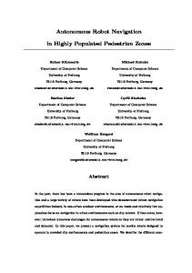
Fig. 1. The omnidirectional vision sensor used in the experiments.
called reference locations because the robot will refer to them to locate itself in the environment. The corresponding images are called reference images. When the robot moves in the environment, it can compare the current view with the reference images stored in its visual memory. When the robot finds which one of the reference images is more similar to the current view, it can infer its position in the environment. If the reference positions are organised in a metrical map, an approximate geometrical localisation can be derived. With this technique, the problem of finding the position of the robot in the environment is reduced to the problem of finding the best match for the current image among the reference images. The problem now is how to store and to compare the reference images, which for a wide environment can be a large number. As we will see in Section 2.1, different methods have been proposed. In this paper, we have fully developed a method we proposed in a previous work [10]. The robot is equipped with an omnidirectional camera and takes a set of omnidirectional images at the reference locations, then it compares the current omnidirectional image with the reference images. In order to store and match a large number of images efficiently, we transform each omnidirectional view into a compact representation by expanding it into its Fourier series. The agent memorises each view by storing the Fourier coefficients of the low frequency components, that we call the “Fourier signature” of the image. This drastically reduces the amount of memory required to store a view at a reference location. Matching the current view against the visual memory is computationally inexpensive with this approach. Details on how to calculate the Fourier signature from the original image are given in Section 2.1. In Section 2.2, we will describe the process of matching the current view against the visual memory. This process is derived from calculating the degree of 3
Fig. 2. An omnidirectional image taken at a reference location.
Fig. 3. The panoramic cylinder created by the omnidirectional image of Fig. 2.
similarity between two omnidirectional images using the signatures associated to them. In Section 2.3, we will show experimental evidence of what we called hierarchical localisation in a complex real-world environment in which many objects are present. In Section 3.1, we will show experiments in which the robot explores a new environment and memorises the local views at many locations. When the exploration phase is finished, it organises the memorised views so that they reflect the geometry of the environment. In Section 3.5, we explain how the robot plans its navigation toward a destination in a reactive manner by using its self-organised memory.
2
Image-based Localisation
As we pointed out in the introduction, the first problem to tackle when building an image-based localisation system is to find a manageable way of storing and comparing the reference images. The aim is to have a data set that fully describes the environment and enables the system to reliably associate the current view with the reference view taken at a nearby location, while keeping the dataset small enough to be easily stored and quickly processed. The first step, in order to lower the number of required reference images, is to use an omnidirectional camera. In fact, if the robot is fitted with a standard perspective camera, the view of the environment from a certain location 4
changes with the direction of gaze. To be able to recognise this point regardless of the instantaneous heading, the robot needs to take several pictures in different directions. The amount of memory required to store and retrieve such a large number of images can rapidly grow to an unmanageable size. A solution can be to constrain the movements of the robot in order to keep the camera pointing at the same location [3], but this greatly limits the motion of the robot. Another solution can be to extract from the images some features that reduce the amount of required memory while retaining a unambiguous description of the image [20]. Nevertheless, working with a perspective camera, collecting such a large number of images is tedious and time consuming. Therefore, we used the omnidirectional camera depicted in Fig. 1. This camera mounts an hyperbolic mirror with a black needle at the apex of the mirror to avoid internal reflections on the glass cylinder [9]. A single omnidirectional image gives a 360◦ view of the environment from a certain location, see Fig. 2. One might object that omnidirectional images have a low resolution, but this usually is not a limitation in tasks like navigation and localisation. In fact, we are more interested on the position of the objects than in the details on their surfaces. Actually, to some extent, the low resolution can be an advantage, because it lowers the number of pixels to be processed to extract the desired information. We will show that the relatively low-resolution images we used contain enough information for the localisation and navigation task.
2.1 Image signature
Let us come to the second step, the comparison of the current image with the reference images. The simplest approach might appear to be some sort of direct comparison of two images pixel by pixel, but this will force us to store the whole image using much memory. We propose to use what we call a Fourier signature to represent the omnidirectional images. The Fourier signature is computed in three steps. First, the omnidirectional image is transformed in a panoramic cylinder, this is a new image obtained unwarping the original omnidirectional image, as depicted in Fig. 3. Second, we calculate the 1-D Fourier transform of every line of the panoramic cylinder and we store in a matrix the Fourier coefficients line by line. Third, we keep only a subset of the Fourier coefficients, those corresponding to the lower spatial frequencies, as signature for the image. Note we do not calculate the Fourier transform of the original omnidirectional image, but we calculate the Fourier transform of the panoramic cylinder. This simplifies the problem of calculating the image similarity. First of all, the panoramic cylinder is a periodic function along the x-axis which, firstly, simplifies the calculation of the Fourier transform and secondly, is the natural 5
Fig. 4. Two panoramic cylinder acquired at the same location before and after a rotation on the spot. The dashed box indicates the spatial shift a between the two images.
representation for implementing a rotational invariance. As we said, the robot must be able to match the current view with the corresponding reference image regardless of the current heading. So, we need to introduce a rotational invariance in the calculation of the similarity between two images. Using the Fourier coefficients as a signature for the images, this problem is also addressed. Let us explain how it works. If the robot grabs two omnidirectional images at the same location but with different headings, these two images are actually the same omnidirectional image rotated about its centre. The amount of rotation corresponds exactly to the number of degrees the robot rotated. This means the two panoramic cylinders created by unwarping the omnidirectional image are actually the same image just shifted along the x-axis, like in Fig. 4. Let see how this consideration affects the Fourier transform of the two images. If f (x) is one row of the first panoramic cylinder, f (x − a) is the corresponding row of the shifted panoramic cylinder and by applying the Shift Theorem, we can write: F{f (x − a)} = e−j2πas F{f (x)}
(1)
where F{f (x)} is the Fourier transform of f (x). In other words, the Fourier transform of a shifted signal is equal to the Fourier transform of the original signal multiplied by the unit magnitude complex coefficient e−j2πas . This property is valid for every row of the panoramic cylinder. This means that the amplitude of the Fourier transform of the shifted image is not changed and there is only a phase change, proportional to the amount of shift a. Coming back to our panoramic images, we can then associate the magnitude of the Fourier transform to the appearance of the environment from a particular place and the phase of the Fourier transform to the heading of the robot. In such a way, when the robot is turning on the spot and the apparency of the environment is not changing, the magnitude of the Fourier transform does not change. What is changing is the phase of the Fourier transform and the amount of change is proportional to the change in the heading. Associating the 6
Fig. 5. The power spectrum of the Fourier transform of the image in Fig. 3. Note that only the first 30 components are shown and components after the 15th have very small values and so can be neglected in the calculation of the similarity function.
apparency of the environment, and then the position of the robot, to the magnitude of the Fourier transform and the heading of the robot to the phase of the Fourier transform, we obtained both the desired rotational invariance and a way to calculate the difference between the current heading and the heading associated to the reference image. For further discussion of the rotational invariance using the Fourier transform, see also [17]. Other authors used different approaches for reducing the memory requirement of omnidirectional images. The most popular technique is to extract a set of eigenimages from the set of reference images and to project the images into eigenspaces. The drawback of such systems is that they need to further preprocess the panoramic cylinder images they created from the omnidirectional image in order to obtain the rotational invariance as in [1], in [11] and in [6] or to constrain the heading of the sensor as in [12]. A different approach might be to create a signature for the image based on the colour histograms of vertical sub-windows of the panoramic image, as in [7]. They implemented a rotational invariance by matching the colour histograms of sub-windows regardless the position they appear in two panoramic images. However, this approach based on colours is not useful in a office environment with poor colour information (like the one we presented in the experiments) where the objects are almost gray and white. The reduction in the memory requirement with our method is large. Figure 2 shows a 640 × 480 pixels omnidirectional image. Figure 3 shows the 512 × 80 pixels panoramic cylinder created from this image, and Fig. 5 shows a plot of the magnitude coefficients of its Fourier series. The Fourier signature as7
Fig. 6. The values of similarity of an input image with respect to nearby reference images. Every curve represent the similarity values calculated with Fourier signatures with a different number of Fourier components.
sociated to the image weights only 19Kb, as we store the magnitude and the phase component of the first 15 Fourier components for everyone of the 80 rows of the panoramic cylinder. As the figure shows, dominant power exists in the frequencies before the 15th component and higher frequencies can be considered not to bring additional information. This is shown in Fig. 6, where we plotted the similarity of an input image against nearby reference images. The similarity between the input images and the reference images have been calculated with Fourier signatures composed of a different number of Fourier components. One can see how, using only 2 or 5 Fourier components the discriminant power of the similarity function is low and does not allow the system to clearly distinguish which of the reference images is most similar to the input image, while if more than 15 Fourier components are used (e.g. 50 or 256) there are no improvements and sometime the performance is even worse. The reason is that only the low frequency components convey information useful for localisation purpose and that very high frequency components are dominated by noise, so they can spoil the localisation. As a result, we represent the omnidirectional image with just the 15 values of the first 15 Fourier components. In the next section, we will describe how the Fourier Signatures can be used to assess the degree of similarity between different images. 8
Fig. 7. The plot of the dissimilarity function values versus the distance between the reference image and the current image. The different lines in the plot represent different pairs of reference image - current image.
2.2 Similarity computation
To compute the similarity between two omnidirectional images we first define a Dissimilarity function that uses the two Fourier Signatures associated to the images. The dissimilarity Dis(Oi , Oj ) between the omnidirectional images Oi and Oj is: Dis(Oi , Oj ) =
l−1 m−1 X X
|Fiy (k) − Fjy (k)|
(2)
y=0 k=0
where Fiy (k) and Fjy (k) are the Fourier coefficients of the k-th frequency of y-th row of Oi and Oj , l is number of rows of the panoramic cylinder, and m is the number of Fourier components in the Fourier signature. The higher the dissimilarity value, the more two images are dissimilar. The dissimilarity function is defined as the L1 norm of two Fourier signatures: The plot in Fig. 7 depicts how the value of the dissimilarity function changes depending on the distance between the positions where the current image and the reference image were taken. The different lines in the plot represent five different pairs of reference image-current image taken in a cluttered office environment. The dissimilarity linearly increases with the distance within a short range, Fig. 7. Augmenting the distance between the two images, the value of the dissimilarity function steadily grows, but after a certain distance it saturates. This happens because when the two images are taken at points that are far apart, there is no correlation at all between the two images. The 9
Fig. 8. The values of the similarity functions calculated at every reference point for the current image. The empty circles on the XY plane represent the reference images. The cross represents the actual position of the current image. The height of the surface at every reference location is proportional to the degree of similarity between the reference image and the current image.
absolute value of the dissimilarity function is unimportant – it depends on the environment structure in a non-trivial way. What is important, in our approach, are the relative values obtained for the current image against all the reference images. To stress this concept, we introduced the concept of similarity function, re-scaling the dissimilarity values to lie between the two arbitrary values 0 and 1000. The rescaling in done on the whole dataset of reference images. Sim(Oi , Oj ) = 1000 − 1000
Dis(Oi , Oj ) − M ini,j {Dis(Oi , Oj )} (3) M axi,j {Dis(Oi , Oj )} − M ini,j {Dis(Oi , Oj )}
In Fig. 8, the surface represent the values of similarity of the current input image with respect to all reference images in the environment imaged in Fig. 3 and sketched in Fig. 10. The empty circles represent the position of the reference images, the cross the position of the current input image, and the surface height at every reference position represents the similarity value between the input image and the reference image. As we said, to calculate the position of the robot, the system finds the reference image with the highest value of the similarity function. This gives a topological localisation for the robot. In other words, we do not know where the robot is, but we know that it is closer to the location of the matched reference image, than to any other reference location. As we will see in Section 3, this consideration, combined with the linearity of the similarity function for small distances make it possible to extract some geometrical information about the localisation of the robot and the geometry of the environment as well. However, most of the time for tasks like navigation 10
a precise geometrical localisation is not necessary. It is enough for the robot to have a topological localisation and in most situations the robot can effectively navigate with a broad topological localisation. In fact, the localisation accuracy with which the robot needs to navigate depends on the environment and on the current action the robot is performing. If the robot is crossing a wide open space, it does not need to know where it is down to the centimetre, but if it has to enter a door the accuracy must be higher. This is similar to the behaviour we experience walking down a street of an unknown town using a map. When we are following the High Street, we do not need to know our exact position on the map, but when we have to take a detour or to enter a building we need to reduce the uncertainty about our position, maybe looking for additional environmental clues. We called this process hierarchical localisation. The word hierarchical was chosen to indicate the robot can calculate more and more precise self-localisation areas, as will be explained in the next section.
2.3
Hierarchical Image-based Localisation
Other authors have also highlighted the need for different localisation accuracies depending on the kind of motion required by the robot. The work in [6] is an example of a vision-based navigation system that uses different localisation accuracies for different tasks. This system uses two different vision-based navigation strategies: topological navigation and visual-path following navigation. The system switches between these two alternatives depending on the situation. The drawback of this solution is that visual path following requires handmade design and an accurate control system. We solved the requirement of a different localisation accuracy within the frame of image-based navigation using the same technique described in Section 2, actually simplifying this technique. To explain how this work, we need to give some insight on the meaning of the Fourier coefficients we can calculate from the panoramic cylinders. When we calculate the Fourier transform of a brightness signal, such as one row of the panoramic cylinder, we are decomposing this signal into its components on a set of basis functions. These basis functions are related to the spatial brightness variation. The first basis function, the one with zero frequency, is the constant brightness signal and the coefficient associated with it gives the level of brightness of the image. The basis functions with higher frequencies give the importance of the brightness pattern of corresponding frequency. When we are calculating the similarity function for two images we are summing up all the contributions from the different frequency components. When looking for the similarity between two images, we can see that the average brightness of the images changes slowly with the distance between the 11
Fig. 9. An example of hierarchical localisation. The number of Fourier components used to calculate the similarity function increases from left to right. The empty circles represent the reference images. The full circle represents the actual position of the current image, and the grey area represents the calculated possible locations of the robot.
two images (the same applies to low frequency brightness pattern), while the distribution and the presence of high frequency brightness patterns changes much faster. This is because, when one observes the environment from different locations one experience different perspective effects and different occlusions. Due to parallax, occlusion of distant objects (i.e. high frequency brightness patterns) change much faster. Therefore, we can expect that the low frequency components of the Fourier transform of the two images are more similar in a larger interval of distances than the higher frequency components. This means that, if in the calculation of the similarity function, we stop the calculation of the sum in Eq. 3 at the first Fourier components, our current image will match not only the closest reference image, but also a larger number of reference images distributed in the surrounding of the current position. As a result, we can have a localisation with a variable accuracy just by choosing the number of Fourier components to compare in the similarity function. This saves computational power as well. In fact, if the robot needs only a broad localisation it does not need to calculate the inner sum in Eq. 3 for every value of k; it can just stop after the first few values. The result is to match the current view not only with the closest view but also with other reference views close to it. When a more precise localisation is needed, as in a situation in which the robot has to manoeuvre in a cluttered environment, the sum can be extended to higher values of k in order to have a more strict matching against only one reference image. The localisation accuracy one can achieve with this technique, as with all image-based approaches, is limited to the 12
distance between two successive reference images 1 . In Fig. 9 is depicted a graphical representation of the hierarchical localisation achieved with our system. The empty circles represent the reference images. The cross represents the actual position of the current input image. The possible position of the robot, as calculated by the system, is represented by the grey area. The number of Fourier components used to calculate the similarity function increases from left to right, consequently the grey area showing the possible localisation of the robot decreases, giving a more and more precise localisation. In this test the reference images were taken on a 25 cm grid in an office environment cluttered with many pieces of furniture, as you can see from pictures in Fig. 2 and Fig. 3. In Fig. 10, we present the hierarchical localisation obtained at different locations in the same environment. The figure also sketches a rough map of the test environment, in which objects appear in different colours. Lighter boxes represent lower objects (e.g. desks or chairs), darker boxes represent taller objects (e.g. filers or shelves). Currently, we are investigating the relation between the shape of the localisation areas and the disposition of the objects in the environment. In summary, our method provides a direct way of calculating the hierarchical localisation for the robot by comparing the frequency spectrum of the current image with the frequency spectrum of the set of reference images. Broad localisation is provided at minimal computational cost, just comparing very few frequency components. When higher accuracy in localisation is needed, the system will use additional computational power. In the next section we will present the ability of the robot to self-organise the set of reference images on a map.
3
3.1
Memory-based Navigation
Organising the reference images
As we saw from Fig. 7, in the short range there is a certain linearity between the value of the similarity function and the distance between the two images. So, we can give an estimation of the real distance between the two images. This is a one dimensional measure, however, and we cannot directly infer the environment geometry from it. We can only know that the first image will be 1
Actually, to some extent is possible to interpolate between to images, using the linearity of Fig. 7 to have a finer localisation.
13
Fig. 10. Several examples of hierarchical localisation at different places in the environment. The layout of the room in which experiments were performed is shown and the boxes represent the objects in the environment. Lighter boxes represent shorter objects, darker boxes represent taller objects.
within a circle of a maximum radius from the second image. In the following, we propose a method for the automatic organisation of the reference images, that is, visual memory, into a lattice that reproduces the geometry of the environment. 14
3.2
Spring model
We propose to use a spring model to arrange the observation points according to the geometry of the environment. As stated earlier, we are using an omnidirectional camera as the only sensor. We do not use any other sensors (e.g. odometers or GPS), so the robot does not have access to the actual locations of the observation points. The basic idea is as follows. Since the similarity provides a measure of the 1D distance between observation points, we arrange the points in a 2D lattice in such a way that the inconsistency between the observed similarity is minimised. If three omnidirectional images are acquired at three different positions, [O1 , O2 , O3 ], we arbitrarily fix the position of the first one, and then we arrange the second and third points at the distances specified by the three similarities Sim(O1 , O2 ), Sim(O1 , O3 ) and Sim(O2 , O3 ). In the general case, in a set of n reference image, we have m measures of similarity where m is: n m= 2
!
(4)
Usually the arrangement that satisfies all measures cannot be found. Thus, we organise the reference image on a spring lattice and we minimised the energy of the lattice. In this model every node of the lattice (i.e. every position at which an omnidirectional image was taken) is attached to every other node of the lattice with a spring, Fig. 11(a). The spring length is proportional to the distance calculated with the similarity function. If two images are arranged at a distance closer than the one calculated by the similarity function, the spring will push away the two images; if they are arranged at a farther distance, the spring will pull them closer. As with a real spring, the force of each spring is proportional to the displacement between the spring length (the calculated distance for the images) and the images distance on the lattice. In this way the nodes of the lattice (the images) will reach an equilibrium state, where the nodes are arranged in a way that minimises the inconsistency between the observations, that is, the total tensions of the springs (Fig. 11(b)). When a new omnidirectional image is added to the set, this process is repeated. For the actual implementation, we should modify the spring model. In fact, as depicted in Fig. 7, the distance estimated from the similarity value becomes unreliable for images separated by great distances. Fig. 12(a) shows the dependence of the error E(d) in the calculation of the distance between two images from the distance d that separates the two images. The error remains small for a short distance, but becomes extremely large for longer distances. The spring model should include the reliability of the distance estimation. This can be performed by allowing spring length to affect the spring coefficient. We used 15
Fig. 11. A sketch of the physical simulation used to find the stable state of the spring model.
Fig. 12. (a) Error function associated to the distance between two images calculated with the similarity distance. (b) Non-linear characteristic of the springs.
the following definition for the spring coefficient K: E(x) log 0.1 K(x) = e E(x1 )
(5)
where x is the distance between the images and x1 is the maximum distance at which there is a correlation between the images. The dependence of the spring coefficient on the distance is highly non-linear, and it is depicted in Fig. 12(b). The force that can be exerted by long springs is very small compared to the force of short springs (the coefficient is less than 0.1). So, short springs will dominate the disposition of the nodes of the lattice. This means that the forces that dominate the organisation of the nodes of the lattice are based on reliable estimations of the actual distance between the images. The result is a distribution of images in the explored space that faithfully reproduces the relative locations of the reference images in the environment, as we will see in the experiment section. 16
Fig. 14. The disposition of the points where the reference images were taken
Fig. 13. Overview of the room where the experiment took place.
3.3
Experimental results
To investigate the feasibility of our idea, we ran another series of experiments in an office cluttered with many pieces of furniture, as shown in Fig. 13. A mobile robot fitted with an omnidirectional sensor was moved around the room. The robot took omnidirectional images every 30 cm, on the grid reproduced in Fig. 14. The grid is 270 × 210cm wide. The robot then ran the physical simulation to arrange the stored view in a lattice. The arrangement of the grid points derived from the similarities between the views is given in Fig. 15; it reflects the environment geometry except for the neighbours of the room boundary. This is because the boundary images are just pulled inward and there are no outer images to balance the force of the inner images.
3.4
Improving the lattice
The above mentioned method fails, if the environment contains some periodicity. In fact, similar omnidirectional images appears at different places in the environment. So, places that look similar but are far apart are mapped close to one and other, because of the low value of the similarity function. The result of this is that the topology of visual memory differs from that of the environment. If the environment is a wide space, the likelihood of this happening increases. Remember that up to now, we have used only the magnitude components of the Fourier signature, and we did not use any kind of motion sensor. However, if we also include the phase component of the Fourier transform, we can obtain qualitative information about the agent’s motion direction in addition to the position of the robot. Thus, we can arrange the visual memory to reflect the environment geometry by using the motion information as a constraint in the organisation of the lattice. By comparing the phase components of the Fourier 17
Fig. 15. Reconstructed environment geometry (the line segments are drawn only for easy understanding).
series of two omnidirectional images, we can estimate the difference in heading between the two images. The error in the direction estimation is about 10%. The constraints assigned to the position of the nodes of the lattice by the information on the motion of the robot make it possible to apply our method to a wider space. The grid shown in Fig. 16 is 540 × 540cm wide. The robot was moved in a zigzag path, the robot heading is shown by the arrows, and it took images every 60 cm. The bold lines in Fig. 16 indicate the path of the robot, the arrows indicate the motion direction of the robot, and the circles indicate the position of the reference images. In this case, uncertainty concerning the motion direction is within 15%, and uncertainty in the distance between two observation points is within 10%. The environment structure presents some periodicities but, as Fig. 17 shows, the coarse structure of the environment is retrieved correctly by our spring system. The topology of the environment is kept in the visual memory despite the coarse robot motion constraints. If one had take closer images (e.g. on a 30 cm grid), the structure of the environment could be retrieved more faithfully. However, our aim is to show that even such a coarse representation can be used for a reactive navigation. In the next section, we explain how the robot can use the retrieved coarse map, to go from a starting location to a goal location.
3.5 Navigation
Once the robot has organised the position of the reference omnidirectional images in a map, it can use the obtained environment map for memory-based 18
Fig. 16. The positions at which the images were taken in the experiment in a large environment.
Fig. 17. The reconstructed environment geometry using the coarse information on the motion of the robot.
Fig. 18. (a) The reconstructed environment geometry with the desired motion direction to reach the destination point. (b) The actual positions of the images in the environment with the real path followed by the robot while navigating.
navigation to reach a destination from the current position. In Fig. 18(a) is represented a portion of the visual memory of the test environment acquired by the agent. Note that, even if the geometry of the disposition of the reference locations is significantly distorted with respect to the real environment, the topology remains unchanged. The robot’s task is to reach the destination guided by its visual memory. Our strategy is as follows. Starting with the given goal, the agent expands a search tree and assigns a motion direction to each observation point, or reference image Oi . For every reference location, the directions toward the destination can be determined by comparing the Fourier phase components as described in the previous section. In Fig. 18(a) the circles indicate the reference omnidirectional images and the arrows indicate the motion direction the robot has to follow to go from that 19
reference position toward the goal position. In Fig. 18(b) the real position of the reference image in the environment is depicted. The robot starts at the starting point close to location O2 . It grabs an omnidirectional image and finds its location as the starting point O2 by searching for the most similar image in its memory. From O2 , the agents moves along the assigned direction A1 . From its environment memory, the robot expects to move toward O4 . It may, however, move toward O5 rather than O4 , because of the distortion of the memory arrangement. This is not a problem because the navigation algorithm is reactive. When the robot grab a new image and looks in the memory for the corresponding match, the new image matches O5 . The robot will infer it has actually arrived in the vicinity of O5 . At O5 , the agent moves along the assigned direction A2 . By iterating these steps, the agent arrives at the destination. The reactive strategy used for navigation overcomes the distortion of the calculated geometry, and is successful in navigating the robot in the environment using image-based navigation. However, to navigate in a much larger environment, we need to divide the environment into sub-areas and assign sub-goals in them for guiding the robot to its destination. This is a problem for our future study. Moreover, the path followed by the robot might be non-optimal, but this is out of the scope of this research.
4
Conclusions and Future Work
The purpose of this paper is to show how omnidirectional images have a set of properties that has not been exploited by other authors. In this paper we proposed a new technique of image-based navigation for an autonomous robot. Using this technique, we created a topological map consisting of a set of omnidirectional images (views) that the robot autonomously acquires and organises into its visual memory. Every image is one node of the map. As we stated, it is not possible to compare the image directly because this will require storing the whole image with intensive requirements in memory storage and computational power. Therefore, we propose a new method in which every image is represented by the components of its Fourier transform. We defined a similarity function that can assess the degree of similarity between two images using the Fourier signatures. As we saw in the experiments, the first 15 components carry enough information to correctly match the current image with the corresponding reference image. The definition we proposed for the similarity function makes it possible to realise a hierarchical localisation of the robot, which is useful for navigating in a large scale environment. Another advantage of the proposed similarity function is the capability of the system to self-organise its visual memory. This is achieved running a physical simulation of a lattice where every node represents an omnidirectional image 20
and every node is connected to the others with a spring. The model of the spring was modified to take into account the characteristics of the similarity function. In summary, the original contribution of this paper is that we highlighted four properties of the Fourier transform of omnidirectional images: • the magnitude of the Fourier components are related to the position of the robot; • the phase of the Fourier components are related to the heading of the robot; • by using the Fourier signatures a high data compression can be achieved; • a hierarchical localisation is embedded in this approach; • the similarity function we defined is effective in the proposed method to self-organise the visual memory; The next step will be to integrate in the presented localisation and navigation system the image-based Monte-Carlo localisation technique we developed to manage the uncertainty in the estimation of the position [16]. We demonstrated the ability of tracking the robot position in order to handle a multimodal probability distribution of the robot position that can offer robustness in case of a possible false match (for instance, in environments with periodical structures or perceptual aliasing) or in case of error recovery (like in the kidnapped robot problem). At the time of writing, we are carrying on new experiments in a outdoor environment. The feeling is that because the current system does not make any assumption on the structure of the environment, it should work on outdoor images without any modification. We want to test the navigation system on a much larger environment than that of the indoor experiments. There is also room for improvement in the assessment of similarity between images. The similarity function can be improved. One possibility could be to extend Eq. 3 into the following function: Dis(Oi , Oj ) =
l−1 m−1 X X
αk |Fiy (k) − Fjy (k)|
(6)
y=0 k=0
where the parameters αk are weights that can give more importance to some Fourier components with respect to others. At the moment every component of the Fourier transform has the same weight, namely, 1, and this results in giving more importance to the low frequencies components that, as shown in Fig. 5, have preponderant values. The problem of choosing the right weights is not trivial because they depend on the structure of the environment. The natural extension of the hierarchical localisation is a hierarchical descrip21
tion of the environment in which the density of the reference images in the space is no longer constant but depends on the structure of the environment. In fact, if we consider an empty space where the reference images are very similar, we can represent this space with just a single reference image representative of all close reference images.
5
Acknowledgements
We would like to thank Prof. T. Nakamura for the fruitful discussion we had on this topic, T. Minato for his help during these experiments, S. Koizumi for providing the software for building the panoramic cylinders, and M. Furukawa for collecting the image sets, K. F. MacDorman his help in correcting the paper draft, and M. Zoccarato for his help with the figures. This research has been partially supported by the Italian Ministry for Education and Research (MURST), the Italian National Council of Research (CNR), the Parallel Computing Project of the Italian Energy Agency (ENEA), the University of Padua, and by the University of Wakayama.
References [1] H. Aihara, N. Iwasa, N. Yokoya, and H. Takemura. Memory-based self-localisation using omnidirectional images. In Anil K. Jain, Svetha Venkatesh, and Brian C. Lovell, editors, Proc. of the 14th International Conference on Pattern Recognition, volume vol. I, pages 1799–1803, 1998. [2] W. Burgard, D. Fox, M. Moors, R. Simmons, and S. Thrun. Collaborative multi-robot exploration. In Proceedings of the IEEE International Conference on Robotics and Automation (ICRA). IEEE, 2000. [3] R. Cassinis, D. Duina, S. Inelli, and A. Rizzi. Unsupervised matching of visual landmarks for robotic homing using fourier-mellin transform. Robotics and Autonomous Systems, 40(2-3), August 2002. [4] Howie Choset and Keiji Nagatani. Topological simultaneous localisation and mapping (slam): Toward exact localization without explicit localization. IEEE Transaction on Robotics and Automation, 17(2):125–137, April 2001. [5] T. Collett, E. Dillmann, A. Giger, and R. Wehner. Visual landmarks and route following in desert ants. Journal of Comparative Physiology A, 170:pp. 435–442, 1992. [6] Jos´e Gaspar, Niall Winters, and Jos´e Santos-Victor. Vision-based navigation and environmental representations with an omnidirectional camera. 22
[7]
[8]
[9]
[10]
[11]
[12]
[13] [14] [15]
[16]
[17]
[18]
[19]
IEEE Transaction on Robotics and Automation, Vol 16(number 6), December 2000. H.-M. Gross, A. Koenig, Ch. Schroeter, and H.-J. Boehme. Omnivisionbased probalistic self-localization for a mobile shopping assistant continued. In IEEE/RSJ Int. Conference on Intelligent Robots and Systems (IROS 2003), October 2003, Las Vegas USA. Hu and Gu. Landmark-based localisation of industrial mobile robots. International Journal of Industrial Robot, Vol. 27(No. 6):pp. 458 – 467, November 2000. Hiroshi Ishiguro. Development of low-cost compact omnidirectional vision sensors. In R. Benosman and S.B. Kang, editors, Panoramic Vision, chapter 3, pages 23–38. Springer, 2001. Hiroshi Ishiguro and Saburo Tsuji. Image-based memory of environment. In Proceedings of the IEEE/RSJ International Conference on Intelligent Robots and Systems (IROS-96), pages 634–639, 1996. M. Jogan and A. Leonardis. Robust localization using panoramic viewbased recognition. In Proc. of the 15th Int.Conference on Pattern Recognition (ICPR00), volume 4, pages 136–139. IEEE Computer Society, September 2000. B.J.A. Kr¨ose, N. Vlassis, R. Bunschoten, and Y. Motomura. A probabilistic model for appareance-based robot localization. Image and Vision Computing, vol. 19(6):pp. 381–391, April 2001. Benjamin Kuipers. The spatial semantic hierarchy. Artificial Intelligence, 119:191–233, February 2000. Wan Yik Lee, Ph.D. Spatial Semantic Hierarchy for a Physical Mobile Robot. PhD thesis, The University of Texas at Austin, 1, 1996. Emanuele Menegatti, Enrico Pagello, and Mark Wright. Using omnidirectional vision sensor within the spatial semantic hierarchy. In IEEE International Conference on Robotics and Automation (ICRA2002), pages 908–914, Washinton, USA, May 2002. Emanuele Menegatti, Mauro Zoccarato, Enrico Pagello, and Hiroshi Ishiguro. Image-based monte-carlo localisation with omnidirectional images. Robotics and Autonomous Systems, Elsevier, page (to appear), 2003. Tom´aˇs Pajdla and V´aclav Hlav´aˇc. Zero phase representation of panoramic images for image based localization. In Franc Solina and Aleˇs Leonardis, editors, 8-th International Conference on Computer Analysis of Images and Patterns, number 1689 in Lecture Notes in Computer Science, pages 550–557, Trˇzaˇska 25, Ljubljana, Slovenia, September 1999. Springer Verlag. T. Sogo, H. Ishiguro, and T. Ishida. Acquisition and propagation of spatial constraints based on qualitative information. IEEE Trans. Pattern Analysis and Machine Intelligence, Vol.23:pp.268–278, 2001. S. Thrun, M. Beetz, M. Bennewitz, W. Burgard, A.B. Cremers, F. D. Fox, D. Haehnel, C. Rosenberg, N. Roy, J. Schulte, and D. Schulz. Probabilistic algorithms and the interactive museum tour-guide robot minerva. In 23
International Journal of Robotics Research, volume Vol. 19, pages 972– 999, November 2000. [20] J. Wolf, W. Burgard, and H. Burkhardt. Robust vision-based localization for mobile robots using an image retrieval system based on invariant features. In Proc. of the IEEE International Conference on Robotics & Automation (ICRA), 2002.
24