Oct 25, 2009 - and ideal magnitude response produces checker boarding and tiling artifacts in the compressed image. Short reconstructions filters are ...
Mustafa S. Mustafa
ﻣﺼﻄﻔﻰ ﺻﺒﺎح ﻣﺼﻄﻔﻰ.م.م
Image Compression Using Critical Sampling and Mixed Orthogonal-Based Algorithms
Mustafa Sabah Mustafa Al Mansour University Collage
Abstract :
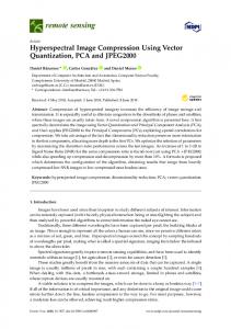
The task of digital image compression has been the subject of several studies over the past decades. Wavelet transform requires filters that combine a number of desirable properties, such as orthogonality and symmetry. Advances in such transform have produced algorithms capable of outperforming in several application of image processing. In addition, Multiwavelets transform has showed promise in removing some of limitations of wavelet. The features of Multiwavelet transform open the way for the application to image compression. These may provide much greater performance than these developed using discrete cosine transform (DCT). Also, there are several methods of computation for Multiwavelet transform, different from scalar wavelet systems in requiring two or more input streams to the Multiwavelet filter bank. Two methods (Mixed and matrix approximation) for computing the Multiwavelet transform are studied. This research attempts to give a recipe for selecting two proposed image compression algorithms based on Multiwavelet approaches, as well as to make comparison of these approaches on color images (256 x 256). After testing several methods of Multiwavelet transform computation for image compression, the mixed method was chosen. This is because the other method introduces more complexity of computation. In data compression applications, one is seeking to remove redundancy not to increase it. Such implementation shows that this transform method gives much better performance. In addition to that it (Multiwavelet) gives a better reconstructed image quality and data rate using the same quantization matrix and in terms of complexity. It was shown that the compressed color image using Multiwavelet transform possesses %80 of compressed image . Therefore the Multiwavelet transform can support a low loss of resolution of reconstructed images which is a desirable feature. 10th Scientific Conference 24-25 Oct.2009
- 120 -
2009 ﺗﺸــﺮﻳﻦ اﻻول25-24 اﻟﻤﺆﺗﻤـــﺮ اﻟﻌﻠﻤــﻲ اﻟﻌــﺎﺷـﺮ
AL-Mansour Journal / No.14/ Special Issue /( Part One)
2010
( ) اﻟﺠﺰء اﻻول/ ﺧﺎص/14 ﻋﺪد/ ﻣﺠﻠﺔ اﻟﻤﻨﺼﻮر
1. Motivation of Multiwavelet
In a Multiwavelet transform, the balancing order of the multiwavelet is indicative of its energy compaction efficiency (usually a higher balancing order implies lower mean-squared-error, MSE, in the compressed image). But a high balancing order alone does not ensure good image compression performance. Filter bank characteristics such as shift-variance, magnitude response, symmetry and phase response are important factors that also influence the MSE and perceived image quality. As in the scalar wavelet case, the theory of Multiwavelets is based on the idea of multiresolution analysis (MRA). The difference is that Multiwavelets have several scaling functions. The standard Multiresolution has one scaling function. The translates are linearly independent and produce a basis of the subspace [1]. Multiwavelets have several advantages in comparison to scalar wavelets . Such features as short support, orthogonality, symmetry, and vanishing moments are known to be important in signal processing. A scalar wavelet cannot possess all these properties at the same time . On the other hand, a Multiwavelet system can simultaneously provide perfect reconstruction while preserving length (orthogonality), good performance at the boundaries (via linear-phase symmetry), and a high order of approximation (vanishing moments). Thus Multiwavelets offer the possibility of superior performance for image processing applications, compared with scalar wavelets [1].
2. One-Dimensional Signal Processing With Multiwavelet Filter Banks The low pass filters H and high pass filter G consists of coefficients corresponding to the dilation equation and wavelet equation. The four coefficients for each filter in equations (1) and (2). But in the Multiwavelet setting these coefficients are by matrices, and during the convolution step they must multiply vectors (instead of scalars).
10th Scientific Conference 24-25 Oct.2009
- 121 -
2009 ﺗﺸﺮﻳﻦ اﻻول25-24 اﻟﻤﺆﺗﻤــﺮ اﻟﻌﻠﻤــﻲ اﻟﻌـﺎﺷــﺮ
Mustafa S. Mustafa
ﻣﺼﻄﻔﻰ ﺻﺒﺎح ﻣﺼﻄﻔﻰ.م.م
The scaling function for the Geronimo-Hardin-Massopust (GHM) is shown in figure (1) This means that multifilter banks need n input rows. We will consider several ways to produce those rows. In this section the signals are 1-D[2].
fig.(1). Geronimo–Hardin–Massopust pair of scaling functions.
3 H [ 0] 5 2 1 20
0 H [ 2] 9 20
10 2 4 5 3
0 3 10 2
10th Scientific Conference 24-25 Oct.2009
3 5 2 H [1 ] 9 20
0 H [ 3] 1 20
- 122 -
0 1 2
…….(1)
0 0
2009 ﺗﺸــﺮﻳﻦ اﻻول25-24 اﻟﻤﺆﺗﻤـــﺮ اﻟﻌﻠﻤــﻲ اﻟﻌــﺎﺷـﺮ
AL-Mansour Journal / No.14/ Special Issue /( Part One)
2010
1 20 G[0] 1 10 2
3 10 2 3 10
9 20 G[1] 9 10 2
9 G[ 2 ] 2 9 10 2
3 3 10
1 G[3] 20 1 10 2
( ) اﻟﺠﺰء اﻻول/ ﺧﺎص/14 ﻋﺪد/ ﻣﺠﻠﺔ اﻟﻤﻨﺼﻮر
1 2 0
…..…(2)
0 0
There are four remarkable properties of the Geronimo-Hardin-Massopust (GHM) scaling functions:
They each have short support (the intervals [0, 1] and [0, 2]). Both scaling functions are symmetric, and the wavelets form a symmetric /anti symmetric pair. All integer translates of the scaling functions are orthogonal. The system has second order of approximation [1].
3. Preprocessing for Multiwavelet The approach is to first split each row or column into two half-length signals, and then use these two half signals as the channel inputs into the multifilter. A naive approach is to simply take the odd samples for one signal and the even samples as second signal. It is generally presumed that image data will be locally well-approximated by low-order polynomials, usually constant, linear, or quadratic. The highpass filters are designed to a uniformly zero output when the input has this form. Taking alternating data points as the filter input alters the character of the input signal; hence the filter output will no longer be forced to zero, reducing compression performance. But there is a way around this problem: one may first pre filter the two half-length signals before passing them into the multi filter.[3] The pre filter step adjusts the input signal properties so that one scalar signal is split into two half- signals in such a way that the orders of approximation built into the multi filter are utilized. The pre filtering is generally performed by taking the two signals as a 2*N matrix (where the original 1-D signal has length 2N) and then left multiplying by one or more 2x2 prefilter matrices. We note that the earlier methods have some limitations such as being tied to a specific multifilter or requiring more than one prefilter matrix [4] 10th Scientific Conference 24-25 Oct.2009 2009 ﺗﺸﺮﻳﻦ اﻻول25-24 اﻟﻤﺆﺗﻤــﺮ اﻟﻌﻠﻤــﻲ اﻟﻌـﺎﺷــﺮ - 123 -
Mustafa S. Mustafa
ﻣﺼﻄﻔﻰ ﺻﺒﺎح ﻣﺼﻄﻔﻰ.م.م
4. General Procedure for Computing DMWT Using A Critically Sampled Scheme of Preprocessing: (CSMWT)
A general procedure can be made for computing a single-level 2-D discrete multiwavelets transform using GHM four multifilters and using a criticallysampled scheme of preprocessing (approximation-based scheme of preprocessing) .By using a critically-sampled scheme of preprocessing (approximation-based scheme of preprocessing), the DMWT matrix has the same dimensions of the input which should be a square matrix N*N where N must be power of 2 . Transformation matrix dimensions which should be equal to image dimensions after preprocessing will be N*N for a critical-sampled scheme of preprocessing. There are two orders of approximation types of critically-sampled preprocessing 1st order 2 nd order approximations. For the using GHM scaling function graph values for φ1(1/2), φ2 (1/2), φ2(1) and φ2 (3/2) should be found for first order approximation. For any N*N image matrix and using equation for 1st order approximation-based preprocessing can be summarized as follows where every two rows generate two new rows: a- For any odd row, (1)[sameoddrow] 2(1/ 2)[nextevenrow] 2(3/2)[previousevenrow] newoddrow 2 2(1)1(1/ 2)
(3)
b- For any even row, new even row
same even row 2 (1)
(4)
It can be seen that the values of φ1 (t) and φ2 (t) are non-zero for t Values of [0, 2]. Since these functions are generated from a 256 sample then: 1. φ1 (1/2) = the 64th value in the iterated vector of φ1, 2. φ2 (1/2) =: the 64th value in the iterated vector of φ2 = φ2 (3/2), 10th Scientific Conference 24-25 Oct.2009
- 124 -
2009 ﺗﺸــﺮﻳﻦ اﻻول25-24 اﻟﻤﺆﺗﻤـــﺮ اﻟﻌﻠﻤــﻲ اﻟﻌــﺎﺷـﺮ
AL-Mansour Journal / No.14/ Special Issue /( Part One)
2010
( ) اﻟﺠﺰء اﻻول/ ﺧﺎص/14 ﻋﺪد/ ﻣﺠﻠﺔ اﻟﻤﻨﺼﻮر
3. φ2 (1) = the 128th value in the iterated vector of φ2 . substituting values of φ1 (l/2), φ2 (1) and φ2 (1/2) in Equations (3) for 1" order approximation results,
10th Scientific Conference 24-25 Oct.2009
- 125 -
2009 ﺗﺸﺮﻳﻦ اﻻول25-24 اﻟﻤﺆﺗﻤــﺮ اﻟﻌﻠﻤــﻲ اﻟﻌـﺎﺷــﺮ
Mustafa S. Mustafa
ﻣﺼﻄﻔﻰ ﺻﺒﺎح ﻣﺼﻄﻔﻰ.م.م
new odd row ((0.373615)[same odd row] (0.11086198)[next even row] (0.11086198)[previous even row])
( new even row = (√2 - l)[same even row]
(5)
(6)
for 2nd order approximation, the Equations becomes, new odd row = ((10 / 8 2 ) [same odd row] + (3 / 8 8 ) [next even row] + (3/8 2 ) [previous even row] ) new even row = [same even row]
(7)
(8)
It should be noted that when computing the first odd row, the previous evenrow in Equation (5) is equal to zero. In the same manner, when computing the last odd row. the next even-row in Equation (5) is equal to zero. The same thing is valid for Equation (7). It is obvious now why the dimension of the resulting matrix after approximation-based preprocessing has the same dimension as before preprocessing. The following procedure for computing DMWT using approximation-based preprocessing is valid for both 1st and 2nd order of approximation with one exception of using Equations (5)and (6) for 1st order approximation preprocessing step and Equations (7) and (8) for 2nd order approximations preprocessing step: 1. Checking image dimensions: Image matrix should be a square matrix, N*N matrix, where N must be power of 2. So checking input image dimensions is the first step of the transform procedure. If the image is not a square matrix some operation must be done to the image like resizing the image or adding rows or columns of zeros to get a square matrix. 2. Constructing a transformation matrix: Using the transformation matrix format, an N/2*N/2 transformation matrix should be constructed using GHM After substituting GHM matrix filter coefficients values an N*N transformation matrix results with same dimensions of input image dimensions after preprocessing. 10th Scientific Conference 24-25 Oct.2009
- 126 -
2009 ﺗﺸــﺮﻳﻦ اﻻول25-24 اﻟﻤﺆﺗﻤـــﺮ اﻟﻌﻠﻤــﻲ اﻟﻌــﺎﺷـﺮ
AL-Mansour Journal / No.14/ Special Issue /( Part One)
2010
( ) اﻟﺠﺰء اﻻول/ ﺧﺎص/14 ﻋﺪد/ ﻣﺠﻠﺔ اﻟﻤﻨﺼﻮر
3. Preprocessing rows: Approximation-based row preprocessing can be computed by applying Equations (5) and (6) to the odd- and even-rows of the input N*N matrix respectively for the 1st order approximation preprocessing. For 2nd order, approximation preprocessing can be computed by applying Equations (7) and (8) for preprocessing odd- and even-rows of the input N*N matrix respectively, Input matrix dimensions after row preprocessing is the same N*N. 4. Transformation of image row. a. Apply matrix multiplication to the N*N constructed transformation matrix by the N*N row preprocessed input image matrix. b. Permute the resulting N*N matrix rows by arranging the row pairs 1,2 and 5,6 ...,N-3,N~2 after each other at the upper half of the resulting matrix rows, then the row pairs 3,4 and 7,8,..., N-1,N below them at , the next lower half. 5. Preprocess columns: repeat the same procedure used in preprocessing rows, a. Transpose the row transformed N*N matrix resulting from step 4. b.Repeat step 3 to the N*N matrix (transpose of the row transformed N*N matrix) which results in N*N column preprocessed matrix, 6. Transformation of image columns : transformation of image columns is applied next to N*N column preprocessed matrix as follows: a. Apply matrix multiplication to the N*N constructed transformation matrix by the N*N column preprocessed matrix. b. Permute the resulting N*N matrix rows by arranging the row pairs 1,2 and 5,6 .... N-3, N-2 after each other at the upper half of the resulting matrix rows, then the row pairs 3,4 and 7,8,.... N-l, N below them at the next lower half. 7. The Final Transformed Matrix: to get the final transformed matrix: a. Transpose the resulting matrix from column transformation step. b. Apply coefficients permutation to the resulting transpose matrix. The final DMWT matrix using approximation-based preprocessing has the same dimensions, N*N, of the original image matrix.
10th Scientific Conference 24-25 Oct.2009
- 127 -
2009 ﺗﺸﺮﻳﻦ اﻻول25-24 اﻟﻤﺆﺗﻤــﺮ اﻟﻌﻠﻤــﻲ اﻟﻌـﺎﺷــﺮ
Mustafa S. Mustafa
ﻣﺼﻄﻔﻰ ﺻﺒﺎح ﻣﺼﻄﻔﻰ.م.م
Figure (2) show the color image And the final image after doing Multiwavelet transform by using CSMWT algorithm . Fig (2) A- Original Image, B – Transformed Image
5. Algorithm Transform
For
Computing
Discrete
Multiwavelets
Mixed
Since Multiwavelet decompositions produce two low-pass subbands and two highpass subbands in each dimension, the organization and statistics of multiwavelets subbands differ from the scalar wavelet case. A closer examination of the differences suggests a method for improving the performance of multiwavelets in image compression applications. During a single level of decomposition using a scalar wavelet transform, the 2-D image data is replaced with four blocks corresponding to the subbands representing either lowpass or highpass in both dimensions. For an 8x8 matrix transformed by the case of scalar wavelets, the 1st level of image (2-D Signal) decomposition partitions image data into four sub-bands labeled as LL, HL, LH, and HH, as shown in Figure (3). The lowpass quarter image is a single subband. But when the Multiwavelet transform is used, the quarter image of lowpass coefficients is actually a 2x2 block of subbands . Due to the nature of the preprocessing and symmetric extension method, data in these different subbands becomes intermixed during iteration of the multiwavelet transform. The intermixing of the multiwavelet lowpass subbands leads to suboptimal. 10th Scientific Conference 24-25 Oct.2009
- 128 -
2009 ﺗﺸــﺮﻳﻦ اﻻول25-24 اﻟﻤﺆﺗﻤـــﺮ اﻟﻌﻠﻤــﻲ اﻟﻌــﺎﺷـﺮ
AL-Mansour Journal / No.14/ Special Issue /( Part One)
2010
( ) اﻟﺠﺰء اﻻول/ ﺧﺎص/14 ﻋﺪد/ ﻣﺠﻠﺔ اﻟﻤﻨﺼﻮر
Fig (3) the two steps of decomposition of wavelet
Since these four LL subbands of the multiwavelet transform possess different statistical characteristics, mixing them together using the Multiwavelet mixing transform or decomposition results in further subbands with mixed data characteristics. This implies that typical quantization schemes that assume the statistics in each subband are either lowpass or highpass will not give the best possible results. For image compression process, transform is applied as a first stage in compression process to be followed by quantization step which operates on transform stage output matrix which should be, as much as possible, suitable for much simplification in quantization step. All previously mentioned methods for computing discrete Multiwavelet transform partitions transform image matrix to the basic Multiwavelets subbands. Subbands values are statically different that for a good compression to occur, each subband needs its own quantization matrix which complicates compression process . and increases computations complexity of the process. Therefore, Mixing transform methods are used for most compression processes. Mixing transform results in a mixed subband matrix which is statically similar and yet further simplify quantization process .
6. General Procedure for Computing DMWT Mixed based tansformation:( MOMWT)
Orthogonal-
The following procedure for computing DMWT using an approximation-based Preprocessing is valid for both 1st and 2nd order of approximation with one exception of using Eqs (5)and (6) for 1st order approximation preprocessing step and Eqs. (7) (8) for 2nd order approximations preprocessing step: 10th Scientific Conference 24-25 Oct.2009
- 129 -
2009 ﺗﺸﺮﻳﻦ اﻻول25-24 اﻟﻤﺆﺗﻤــﺮ اﻟﻌﻠﻤــﻲ اﻟﻌـﺎﺷــﺮ
Mustafa S. Mustafa
ﻣﺼﻄﻔﻰ ﺻﺒﺎح ﻣﺼﻄﻔﻰ.م.م
1. Checking image dimensions: Image matrix should be a square matrix, N*N matrix, where N must be power of 2. So checking Input image dimensions is the first step of the transform procedure. If the image is not a square matrix some operations must be done to the image like resizing the image or adding rows or column of zeros to get a square matrix.
2. Constructing a transformation matrix: Using the transformation matrix Format, an N/2*N/2 transformation matrix should be constructed using GHM. After substituting GHM matrix filter coefficients values as given by an N*N transformation matrix results with the same dimensions of input image dimensions after preprocessing.
3. Preprocessing rows: Approximation-based row preprocessing can be computed by applying Equations. (5) and (6) to the odd- and even-rows of the input N*N matrix respectively for the 1st order approximation preprocessing. For 2nd order approximation preprocessing, Equations (7) and (8). For preprocessing odd- and even-rows of the input N*N matrix respectively. Input matrix dimensions after row preprocessing are the same N*N.
4. Preprocess columns a. Transpose the row preprocessed N*N, matrix resulting from step 3, b. Repeat step 3 to the N*N matrix (transpose of the row preprocessed N*N matrix). c. Transpose the resulting matrix from step b which results in a N*N column preprocessed matrix
10th Scientific Conference 24-25 Oct.2009
- 130 -
2009 ﺗﺸــﺮﻳﻦ اﻻول25-24 اﻟﻤﺆﺗﻤـــﺮ اﻟﻌﻠﻤــﻲ اﻟﻌــﺎﺷـﺮ
AL-Mansour Journal / No.14/ Special Issue /( Part One)
2010
( ) اﻟﺠﺰء اﻻول/ ﺧﺎص/14 ﻋﺪد/ ﻣﺠﻠﺔ اﻟﻤﻨﺼﻮر
5. Apply Transformation: by multiplying the transformation matrix by the preprocessed matrix by the transpose of the transformation matrix- This multiplication of the three matrices results in the final discrete Multiwavelets transformed mixed N*N matrix.
Fig (3) A- The original image B - The Transformed image .
7. Gray scale Image Compression A digital gray scale image is typically represented by 8 bits per pixel (bpp) in its uncompressed form. Each pixel has a value ranging from 0 (black) to 255 (white). Transform methods are applied directly to a two dimensional image by first operating on the rows, and then on the columns. as shown in figure (4).
10th Scientific Conference 24-25 Oct.2009
- 131 -
2009 ﺗﺸﺮﻳﻦ اﻻول25-24 اﻟﻤﺆﺗﻤــﺮ اﻟﻌﻠﻤــﻲ اﻟﻌـﺎﺷــﺮ
Mustafa S. Mustafa
ﻣﺼﻄﻔﻰ ﺻﺒﺎح ﻣﺼﻄﻔﻰ.م.م
Loading images Multiwavelet System
Prefilters Operations
Apply Multiwavelet
Image Compression
Postfilters Operations
Reconstruct Image
Display and Save
Fig (4) flowchart for Gray scale Image Compression
8. Colour Image Compression A digital colour image is stored as a three-dimensional array and uses 24 bits to represent each pixel in its uncompressed form. Each pixel contains a value representing a red (R), green (G), and blue (B) component scaled between 0 and 255–this format is known as the RGB format. Image compression schemes first convert the color image from the RGB format to another colour space representation that separates the image information better than RGB.
10th Scientific Conference 24-25 Oct.2009
- 132 -
2009 ﺗﺸــﺮﻳﻦ اﻻول25-24 اﻟﻤﺆﺗﻤـــﺮ اﻟﻌﻠﻤــﻲ اﻟﻌــﺎﺷـﺮ
AL-Mansour Journal / No.14/ Special Issue /( Part One)
2010
( ) اﻟﺠﺰء اﻻول/ ﺧﺎص/14 ﻋﺪد/ ﻣﺠﻠﺔ اﻟﻤﻨﺼﻮر
In this paper the colour images are converted to the luminance (Y), chrominance-blue (Cb),and chrominance-red (Cr) colour space. The luminance component represents the intensity of the image and looks like a gray scale version of the image. The chrominance-blue and chrominance-red components represent the color information in the image. The Y, Cb, and Cr components are derived from the RGB space by the following relations [5]. Y = 16+65.481 *R + 128.553* G + 24.966 *B
(9)
Cb = 128 − 37.797 · R − 74.203 · G + 112 *B
(10)
Cr = 128 + 112 · R − 93.786 · G − 18.214 *B
(11)
Fig (5): Block diagram of the colour image compression.
Fig (6): Block diagram of the colour image compression using Multiwavelet algorithm.
10th Scientific Conference 24-25 Oct.2009
- 133 -
2009 ﺗﺸﺮﻳﻦ اﻻول25-24 اﻟﻤﺆﺗﻤــﺮ اﻟﻌﻠﻤــﻲ اﻟﻌـﺎﺷــﺮ
Mustafa S. Mustafa
ﻣﺼﻄﻔﻰ ﺻﺒﺎح ﻣﺼﻄﻔﻰ.م.م
9. Quantization: Quantization process was to extract the coefficients of transformed image .the quantization discarded a few number of coefficient that have a higher energy (the important features).where the residual coefficient was truncated by the threshold. In the compression the quantization is important because the aim of compression was to eliminate the redundancy data in image. So that the quantization is very useful in image compression [6].
The transformed image
The quantized image
Figure (7) Converting from transformed to quantized image
10th Scientific Conference 24-25 Oct.2009
- 134 -
2009 ﺗﺸــﺮﻳﻦ اﻻول25-24 اﻟﻤﺆﺗﻤـــﺮ اﻟﻌﻠﻤــﻲ اﻟﻌــﺎﺷـﺮ
AL-Mansour Journal / No.14/ Special Issue /( Part One)
2010
( ) اﻟﺠﺰء اﻻول/ ﺧﺎص/14 ﻋﺪد/ ﻣﺠﻠﺔ اﻟﻤﻨﺼﻮر
Table (1) quantization matrix 3
5
7
9
11
13
15
17
5
7
9
11
13
15
17
19
7
9
11
13
15
17
19
21
9
11
13
15
17
19
21
23
11
13
15
17
19
21
23
25
13
15
17
19
21
23
25
27
15
17
19
21
23
25
27
29
17
19
21
23
25
27
29
31
Figure (8): flowchart of quantization
the segment of transformed image 8x8 in Multiwavelet with adaptive method) by a certain value of that matrix, after the division ,rounding the result of quantization. Some of these results can become zero after rounding. This is the step where picture information is lost. This is called quantization and the factors are provided by a quantization matrix. Fig (7) shows the information of image to be quantized.
10th Scientific Conference 24-25 Oct.2009
- 135 -
2009 ﺗﺸﺮﻳﻦ اﻻول25-24 اﻟﻤﺆﺗﻤــﺮ اﻟﻌﻠﻤــﻲ اﻟﻌـﺎﺷــﺮ
Mustafa S. Mustafa
ﻣﺼﻄﻔﻰ ﺻﺒﺎح ﻣﺼﻄﻔﻰ.م.م
10. Zig Zag quantization Quantization of the recent research on image compression depends on the DCT quantization .For this reason we used the quantization matrix of 8x8 is used. The process is made by doing point product (product point by point). Table (2): zigzag sequence 0
1
5
6
14
15
27
28
2
4
7
13
16
26
29
42
3
8
12
17
25
30
41
43
9
11
18
24
31
40
44
53
10
19
23
22
39
45
52
54
20
22
33
38
46
51
55
60
21
34
37
47
50
56
59
61
35
36
48
49
57
58
62
63
Figure (9) flowchart for zigzag
10th Scientific Conference 24-25 Oct.2009
- 136 -
2009 ﺗﺸــﺮﻳﻦ اﻻول25-24 اﻟﻤﺆﺗﻤـــﺮ اﻟﻌﻠﻤــﻲ اﻟﻌــﺎﺷـﺮ
AL-Mansour Journal / No.14/ Special Issue /( Part One)
2010
( ) اﻟﺠﺰء اﻻول/ ﺧﺎص/14 ﻋﺪد/ ﻣﺠﻠﺔ اﻟﻤﻨﺼﻮر
11. Huffman /Run-length Coding The popular coding method for image is the Huffman coding. When coding the symbols of an information source individually, Huffman coding yield the smallest possible number of code symbols per source symbol. Huffman coding depends on two observations: 1. The symbols that occur less frequently will have the same length for the number of bits. 2. Symbols that occur more frequently will have shorter coding for the number of bits. The first step in Huffman’s approach is to create a series of source reductions by ordering the probability of the symbols under consideration and combining the lowest probability symbols into a single symbol that replaces them in the next source reduction. The second step in Huffman’s procedure is to code each reduced source, starting with the smallest source and working back to the original source. The minimal length binary code for a two symbol source, of course, is the symbols 0 and1 [4]. the figure (10) show the procedure of the encoder. Every pixel is mapped onto a variable-length bit string according to a probability table.
Fig (10) flowchart for Huffman encoder 10th Scientific Conference 24-25 Oct.2009
- 137 -
2009 ﺗﺸﺮﻳﻦ اﻻول25-24 اﻟﻤﺆﺗﻤــﺮ اﻟﻌﻠﻤــﻲ اﻟﻌـﺎﺷــﺮ
Mustafa S. Mustafa
م.م.ﻣﺼﻄﻔﻰ ﺻﺒﺎح ﻣﺼﻄﻔﻰ
اﻟﻤﺆﺗﻤـــﺮ اﻟﻌﻠﻤــﻲ اﻟﻌــﺎﺷـﺮ 25-24ﺗﺸــﺮﻳﻦ اﻻول 2009
- 138 -
10th Scientific Conference 24-25 Oct.2009
AL-Mansour Journal / No.14/ Special Issue /( Part One)
2010
( ) اﻟﺠﺰء اﻻول/ ﺧﺎص/14 ﻋﺪد/ ﻣﺠﻠﺔ اﻟﻤﻨﺼﻮر
12. PSNR Peak signal-to-noise ratio (PSNR) is the standard method for quantitatively comparing a compressed image with the original. For colour images, the reconstruction of all three colour spaces must be considered in the PSNR calculation. The MSE is calculated for the reconstruction of each colour space. The average of these three MSEs is used to generate the PSNR of the reconstructed RGB image (as compared to the original 24-bit RGB image). The color PSNR equations are as follows [5]: PSNR = 10log
(12)
MSERGB =
(13)
13. Eight tests of the proposed compression method:After considering eight different color images given in Figure (11)
10th Scientific Conference 24-25 Oct.2009
- 139 -
2009 ﺗﺸﺮﻳﻦ اﻻول25-24 اﻟﻤﺆﺗﻤــﺮ اﻟﻌﻠﻤــﻲ اﻟﻌـﺎﺷــﺮ
Mustafa S. Mustafa
م.م.ﻣﺼﻄﻔﻰ ﺻﺒﺎح ﻣﺼﻄﻔﻰ
اﻟﻤﺆﺗﻤـــﺮ اﻟﻌﻠﻤــﻲ اﻟﻌــﺎﺷـﺮ 25-24ﺗﺸــﺮﻳﻦ اﻻول 2009
- 140 -
10th Scientific Conference 24-25 Oct.2009
AL-Mansour Journal / No.14/ Special Issue /( Part One)
10th Scientific Conference 24-25 Oct.2009
- 141 -
2010
( ) اﻟﺠﺰء اﻻول/ ﺧﺎص/14 ﻋﺪد/ ﻣﺠﻠﺔ اﻟﻤﻨﺼﻮر
2009 ﺗﺸﺮﻳﻦ اﻻول25-24 اﻟﻤﺆﺗﻤــﺮ اﻟﻌﻠﻤــﻲ اﻟﻌـﺎﺷــﺮ
Mustafa S. Mustafa
ﻣﺼﻄﻔﻰ ﺻﺒﺎح ﻣﺼﻄﻔﻰ.م.م
Table
Pic No.
File Size
CR in CSMWT
CR in MOMWT
1
192kB
4.547
5.313
2
191kB
4.106
4.823
3
190kB
4.342
4.941
4
191kB
4.377
4.996
5
190kB
4.226
4.817
6
192kB
4.368
5.322
7
192kB
4.608
5.333
8
192kB
4.554
5.139
Average
191.25
4.391
4.934636
(3) the
compression ratio by both multi wavelet transform algorithm.
10th Scientific Conference 24-25 Oct.2009
- 142 -
2009 ﺗﺸــﺮﻳﻦ اﻻول25-24 اﻟﻤﺆﺗﻤـــﺮ اﻟﻌﻠﻤــﻲ اﻟﻌــﺎﺷـﺮ
AL-Mansour Journal / No.14/ Special Issue /( Part One)
2010
( ) اﻟﺠﺰء اﻻول/ ﺧﺎص/14 ﻋﺪد/ ﻣﺠﻠﺔ اﻟﻤﻨﺼﻮر
the eight images given in fig (11) have some property. The type selected of images was color image (24bit).where the size for all images as in table (11) was 192 KB. The stability for these two main properties with the different compression result of image leads to studies these different. There are the Pic No.
MSE
SNR
PSNR(db)
MAE
third shared property was the dimension of images (256 X 256) pixels.
The
n
dimension of given images must be 2 . The obtained results from the first step are comparison for the compression ratio to both the Multiwavelet transform algorithms. The results of compression in size of output file. As can be shown in table (3) it is clear that the Multiwavelet by MOMWT algorithm give much better compression ratio in comparison with Multiwavelet transform by CSMWT algorithm. On average for the eight pictures given in figure (11) the Multiwavelet compression ratio of MOMWT is (4.934636) while for Multiwavelet in CSMWT is (4.391). The best compression was achieved in the case image 7 . The minimum CR was with image 2.
Table (4) the results of measure distortion in Multiwavelet transform using CSMWT.
1
0.88489223
1.314168
28.661900
68.983109
2
0.99518688
1.543696
28.151757
79.226761
3
0.85001409
1.600319
28.836542
68.851791
4
0.79286393
1.709510
29.138817
60.256561
5
0.82.581863
1.680028
28.961957
66.956924
6
1.14163321
1.320443
27.555538
89.821838
7
1.04388062
1.264654
27.944295
85.696533
8
1.32982178
1.185271
26.892869
109.948792
Average
0.9913604709
1.51436436
28.23503009
78.49701809
10th Scientific Conference 24-25 Oct.2009
- 143 -
2009 ﺗﺸﺮﻳﻦ اﻻول25-24 اﻟﻤﺆﺗﻤــﺮ اﻟﻌﻠﻤــﻲ اﻟﻌـﺎﺷــﺮ
Mustafa S. Mustafa
ﻣﺼﻄﻔﻰ ﺻﺒﺎح ﻣﺼﻄﻔﻰ.م.م
It was found that the Multiwavelet MOMWT gives a better compression ratio. As in table (4) the measurement of distortion was showed. Ratio is achieved with the Multiwavelet transform using critical sampling schema as can be seen as in table (4) the measurement of distortion was showed. Where the Table (5) the results of measure distortion in Multiwavelet transform using mixed orthogonal algorithm. As in table (5) the measurement of distortion was showed.
Where the Table (5) the results of measure distortion in Multiwavelet transform using mixed orthogonal algorithm. As in table (5) the measurement of distortion was showed.
10th Scientific Conference 24-25 Oct.2009
- 144 -
2009 ﺗﺸــﺮﻳﻦ اﻻول25-24 اﻟﻤﺆﺗﻤـــﺮ اﻟﻌﻠﻤــﻲ اﻟﻌــﺎﺷـﺮ
AL-Mansour Journal / No.14/ Special Issue /( Part One)
2010
( ) اﻟﺠﺰء اﻻول/ ﺧﺎص/14 ﻋﺪد/ ﻣﺠﻠﺔ اﻟﻤﻨﺼﻮر
Table (5) The results of measure distortion in Multiwavelet transform using MOMWT
Pic No.
MSE
SNR
PSNR(db)
MAE
1
0.62906276
1.848619
30.143864
41.102478
2
0.81441321
1.886347
29.022356
59.061096
3
0.72453366
1.877475
29.530218
54.643433
4
0.61921825
2.188904
30.212366
42.862885
5
0.45360602
3.058598
31.564016
33.690933
6
1.09327855
1.378845
27.743495
83.827774
7
0.72375466
1.824027
29.534890
49.228668
8
0.74280703
2.121950
29.422044
46.401657
Average
0.7474840
2.0760799
29.548987
53.2533636
14. Conclusions In this research, several conclusions based on the proposed image compression method will be given. These conclusions are based on 8 color images, with different frequency contents, compressed at different compression ratios using the Multiwavelet transform algorithms. The conclusions are as follows. 1. The method of computation of Multiwavelet transform is essential. To keep the transform in-expensive, it must be looking for the mathematical operation. the Multiwavelet transform by MOMWT is implemented faster than CSMWT. The Multiwavelets have smooth basis functions under all integer shifts and they have relatively better magnitude characteristics. 2. This analysis shows that shift-invariance and desirable magnitude response characteristics are the most significant determinants of image compression performance for the Multiwavelets tested. A departure from shift-invariance and ideal magnitude response produces checker boarding and tiling artifacts in the compressed image. Short reconstructions filters are essential to minimize the ringing artifact. Further, a good symmetric extension technique is necessary to avoid border artifacts.
10th Scientific Conference 24-25 Oct.2009
- 145 -
2009 ﺗﺸﺮﻳﻦ اﻻول25-24 اﻟﻤﺆﺗﻤــﺮ اﻟﻌﻠﻤــﻲ اﻟﻌـﺎﺷــﺮ
Mustafa S. Mustafa
ﻣﺼﻄﻔﻰ ﺻﺒﺎح ﻣﺼﻄﻔﻰ.م.م
3. The best Multiwavelet PSNR results for MOMWT algorithm fall short of the best Multiwavelets for CSMWT by 0.2-0.7 dB This performance gap is explained by the difference in their energy compaction efficiencies. In general The Multiwavelets have a higher vanishing orders. So we expect that higher order Multiwavelets will outperform their scalar counterparts in image compression applications of wavelet transform. 4. For most images the proposed scheme improves the perceived image quality for the Multiwavelet at low bit rates although the corresponding PSNR values are for these algorithms lower by 0.2-.0.8 dB. Furthermore, the Multiwavelet decomposition model outperforms JPEG2000.
10th Scientific Conference 24-25 Oct.2009
- 146 -
2009 ﺗﺸــﺮﻳﻦ اﻻول25-24 اﻟﻤﺆﺗﻤـــﺮ اﻟﻌﻠﻤــﻲ اﻟﻌــﺎﺷـﺮ
AL-Mansour Journal / No.14/ Special Issue /( Part One)
2010
( ) اﻟﺠﺰء اﻻول/ ﺧﺎص/14 ﻋﺪد/ ﻣﺠﻠﺔ اﻟﻤﻨﺼﻮر
References
[1]. F. Murtagh, “The Haar Wavelet Transform of a Dendrogram”, Department of Computer Science, University of London, June 26-2005, http://www.cs.rhul.ac.uk/home/fionn/papers/fm37.pdf. [2]. Strela V.,Heller P.N.,Strang G.,Topiwala P.and Heil C.” The Application of Multiwavelet Filterbank to Image Processing”, IEEE Transactions On Image Processing, VOL. 8, No. 4, pp(548-563),April 1999. [3]. Jalal, Z. “ Design And Implementation Of DSP Techniques For Video Compression “ A Phd thesis , University of Baghdad 2004. [4]. Larsen J.” Wavelet Packet Representation Of Textured Regions “http:// www.icg.isy.liu.se/ ,A paper, University of Linkoping 2001. [5]. Image Processing Toolbox for use with Matlab. The Mathworks Inc., Natick MA, second edition, 1997. [6]. R. Neelamani, R. de Queiroz, Z. Fan, S. Dash, and R. G. Baraniuk, “JPEG Compression History Estimation”, Accepted by the IEEE Transactions on Image Processing, 2004, http://signal.ece.utexas.edu/~queiroz/papers/neelsh-journal.pdf.
10th Scientific Conference 24-25 Oct.2009
- 147 -
2009 ﺗﺸﺮﻳﻦ اﻻول25-24 اﻟﻤﺆﺗﻤــﺮ اﻟﻌﻠﻤــﻲ اﻟﻌـﺎﺷــﺮ
Mustafa S. Mustafa
م.م.ﻣﺼﻄﻔﻰ ﺻﺒﺎح ﻣﺼﻄﻔﻰ
ﺿﻐﻂ اﻟﺼﻮر ﺑﺎﺳﺘﺨﺪام ﺧﻮارزﻣﻴﺔ اﻟﺘﺮﻣﻴﺰ اﻟﺤﺎﺳﻢ و ﺧﻮارزﻣﻴﺔ اﻟﻤﺰج أﻟﻌﻤﻮدي
م.م .ﻣﺼﻄﻔﻰ ﺻﺒﺎح ﻣﺼﻄﻔﻰ آﻠﻴﺔ اﻟﻤﻨﺼﻮر اﻟﺠﺎﻣﻌﺔ
اﻟﻤﺴﺘﺨﻠﺺ: ﻣﻬﻤﺔ ﺿﻐﻂ اﻟﺼﻮر اﻟﺮﻗﻤﻴﺔ أﺻﺒﺤﺖ ﻣﻮﺿﻮع ﻟﻌﺪة دراﺳﺎت أآﺜﺮ ﻣﻦ اﻟﺴﺎﺑﻖ .ﺗﺤﻮﻳﻠﻪ اﻟﻤﻮﻳﺠﺔ ﺗﺤﺘﺎج ﻣﺮﺷﺤﺎت واﻟﺘﻲ ﺗﺘﻜﻮن ﻣﻦ ﻋﺪد ﻣﻦ اﻟﺨﺼﺎﺋﺺ اﻟﻤﺮﻏﻮب ﻓﻴﻬﺎ ﻣﺜﻞ اﻟﺘﻨﺎﻇﺮﻳﺔ واﻟﺘﻌﺎﻣﺪﻳﺔ .اﻟﻔﻮاﺋﺪ ﻓﻲ هﺬﻩ اﻟﺘﺤﻮﻳﻠﺔ ﺗﻨﺘﺞ ﺧﻮارزﻣﻴﺎت ﻗﺎدرة ﻟﻠﻌﻤﻞ ﻓﻲ ﻋﺪدت ﺗﻄﺒﻴﻘﺎت ﻟﻤﻌﺎﻟﺠﺔ اﻟﺼﻮر .ﺑﺎﻹﺿﺎﻓﺔ إﻟﻰ ذﻟﻚ ,ﺗﺤﻮﻳﻠﻪ ﻣﺘﻌﺪدة اﻟﻤﻮﻳﺠﺎت ﺗﻈﻬﺮ وﻋﻮد ﻓﻲ إزاﻟﺔ ﺑﻌﺾ اﻟﻤﺤﺪدات ﻟﻄﺮﻳﻘﺔ اﻟﻤﻮﻳﺠﺔ .ﻣﺴﺘﻘﺒﻞ ﺗﺤﻮﻳﻠﻪ ﻣﺘﻌﺪدة اﻟﻤﻮﻳﺠﺎت ﺗﻔﺘﺢ اﻟﻄﺮﻳﻖ ﻟﺘﻄﺒﻴﻘﺎت ﺿﻐﻂ اﻟﺼﻮر .ﺗﻠﻚ اﻟﺘﻄﺒﻴﻘﺎت ﻣﻤﻜﻦ إن ﺗﺠﻬﺰ أداء أآﺜﺮ ﻣﻦ ﺗﻠﻚ اﻟﺘﻲ ﺗﻄﻮر ﺑﻮاﺳﻄﺔ ﺗﺤﻮﻳﻠﻪ اﻟﺠﻴﺐ ﺗﻤﺎم اﻟﻤﺘﻘﻄﻊ .هﻨﺎﻟﻚ ﻋﺪد ﻣﻦ اﻟﻄﺮق ﻟﺤﺴﺎب ﺗﺤﻮﻳﻠﻪ ﻣﺘﻌﺪدة اﻟﻤﻮﻳﺠﺎت ﺗﺨﺘﻠﻒ ﻋﻦ ﻧﻈﺎم اﻟﻤﻮﻳﺠﺔ ﻓﻲ اﺣﺘﻴﺎج ﻣﺼﻔﻮﻓﺔ ﺛﻨﺎﺋﻴﺔ اﻹﺑﻌﺎد ﺑﺎﺛﻨﻴﻦ أو أآﺜﺮ ﻣﻦ اﻟﻤﺪﺧﻼت ﻣﻘﺎرﻧﺔ ﺑﻤﺮﺷﺢ اﻟﻤﻮﻳﺠﺔ واﻟﺬي ﻳﺤﺘﺎج ﻓﻘﻂ اﺛﻨﻴﻦ ﻣﻦ اﻟﻤﺪﺧﻼت .ﻃﺮﻳﻘﺘﺎن ﻟﺤﺴﺎب ﺗﺤﻮﻳﻠﻪ ﻣﺘﻌﺪد اﻟﻤﻮﻳﺠﺎت درﺳﺖ. هﺬا اﻟﺒﺤﺚ ﻳﺤﺎول إن ﻳﻌﻄﻲ اﻟﻮﺳﻴﻠﺔ ﻻﺧﺘﻴﺎر ﺧﻮارزﻣﻴﺘﻴﻦ ﻣﻘﺘﺮﺣﺔ ﻟﻀﻐﻂ اﻟﺼﻮر) (256 x256ﺑﺤﻴﺚ ﺗﻌﺘﻤﺪ ﻋﻠﻰ ﻣﺘﻌﺪد اﻟﻤﻮﻳﺠﺔ .اﻟﻀﻐﻂ ﻓﻲ ﺗﻠﻚ اﻟﻄﺮق ﻳﺴﺘﺨﺪم اﻟﺼﻮر اﻟﻤﻠﻮﻧﺔ.ﺿﻐﻂ اﻟﺼﻮر ﺑﺎﺳﺘﺨﺪام ﺗﺤﻮﻳﻠﻪ ﻣﺘﻌﺪد اﻟﻤﻮﻳﺠﺔ ﻓﻲ اﻟﺒﺪء ﺗﺘﻢ ﺑﺎﺳﺘﺨﺪام داﻟﺔ ﺧﺎﺻﺔ ﺣﻴﺚ ﺗﻄﺒﻖ ﻟﻜﻞ اﻟﺼﻮرة .هﺬﻩ اﻟﻄﺮﻳﻘﺔ ﺗﻌﻄﻲ ﻧﺴﺒﺔ ﺿﻐﻂ اآﺒﺮ ﻣﻦ اﻟﺨﻮارزﻣﻴﺎت اﻟﺘﻲ ﺗﻤﺎﺛﻠﻬﺎ ﻣﺜﻞ . DCT ﺑﻌﺪ ﻓﺤﺺ ﻋﺪدت ﻃﺮق ﻟﺘﺤﻮﻳﻠﻪ ﻣﺘﻌﺪدة اﻟﻤﻮﻳﺠﻪ ﻟﻀﻐﻂ اﻟﺼﻮر .ﻃﺮﻳﻘﺔ اﻟﻤﺰج هﻲ اﻟﻤﺨﺘﺎرة وذﻟﻚ ﺑﺴﺒﺐ إن اﻟﻄﺮﻳﻘﺔ اﻷﺧﺮى ﺗﻘﺪم ﺗﻌﻘﻴﺪ اآﺜﺮﻓﻲ اﻟﻌﻤﻠﻴﺎت اﻟﺤﺴﺎﺑﺔ .ﻓﻲ ﺗﻄﺒﻴﻘﺎت ﺿﻐﻂ اﻟﺒﻴﺎﻧﺎت,أهﻢ ﺷﻲ ﻳﺘﻢ اﻟﺒﺤﺚ وإزاﻟﺔ اﻟﺘﻜﺮار ﻟﻴﺲ اﻟﻌﻜﺲ ﺑﺪون ﺗﻌﻘﻴﺪ .ﻣﺜﻞ هﺬا اﻟﺘﻨﻔﻴﺬ ﻳﻈﻬﺮ هﺬا اﻟﺘﺤﻮﻳﻠﺔ ﺗﻌﻄﻲ أآﺜﺮ أداء ﻓﻲ اﻟﻀﻐﻂ ﻣﻘﺎرﻧﺔ ب اﻟﻤﻮﻳﺠﺔ .ﺑﺎﻹﺿﺎﻓﺔ إﻟﻰ ذﻟﻚ أﻧﻬﺎ ﺗﻌﻄﻲ ﻧﻘﺎوة أآﺜﺮ وﺗﻌﻘﻴﺪ اﻗﻞ .أﻧﻬﺎ ﺗﻈﻬﺮ إن ﺿﻐﻂ اﻟﺼﻮر اﻟﻤﻠﻮﻧﺔ ﺑﻄﺮﻳﻘﺔ ﺗﺤﻮﻳﻠﻪ ﻣﺘﻌﺪدة اﻟﻤﻮﻳﺠﺔ ﺗﺼﻞ إﻟﻰ اآﺜﺮ ﻣﻦ %80آﻨﺴﺒﺔ ﺿﻐﻂ .
اﻟﻤﺆﺗﻤـــﺮ اﻟﻌﻠﻤــﻲ اﻟﻌــﺎﺷـﺮ 25-24ﺗﺸــﺮﻳﻦ اﻻول 2009
- 148 -
10th Scientific Conference 24-25 Oct.2009