Jul 5, 2007 - document & medical imaging and facsimile transmission. The intelligence needed is not ..... Professor in the Department of EEE, Sri Venkateswara. University, Tirupati, Andhra ... (India) and fellow of Institute of Electronics &.
IJCSNS International Journal of Computer Science and Network Security, VOL.7 No.7, July 2007
274
Image Compression Using Transform Coding Methods Mr. T.Sreenivasulu reddy
Ms. K. Ramani SVEC, Tirupati SVUCE, Tirupati, India. India.
Summary The proposed work describes the algorithms for Image Compression using Transform Coding Methods: Modified Hermite Transform (MHT), Discrete Cosine Transform (DCT) and Wavelet Transform (WT).In MHT and DCT, the given image is divided into NxN subblocks and transformation is applied to each block .Then, a threshold value is selected such that to minimize the mean square value between Original image and Reconstructed image. Wavelet Transform decomposes signal into set of basis functions. These basis functions, called wavelets, are obtained from a single prototype wavelet by dilations and contractions as well as shifts. Using Discrete time Wavelet Transform any given image can be decomposed into ‘n’ levels. The lower levels of decomposition correspond to higher frequency sub bands. In particular, level 1 corresponds to highest frequency sub-band and it is the finest level of resolution. Correspondingly nth level corresponds to lowest frequency sub-bands and has coarsest resolution.In this work, different wavelet Transforms like Symlet, Haar, Daubechies and Coiflet will be used to compress the 1-D,2-D and color images and these results will be compared with DCT and MHT results.
I. Introduction In the field of image processing, image compression is the current topic of research. Image compression plays a crucial role in many important and diverse applications, including televideoconferencing, remote sensing, document & medical imaging and facsimile transmission. The intelligence needed is not served with older techniques of compression such as Fourier Transform, Hadamard and Cosine Transforms, which suffer from larger mean square error between original and reconstructed images. The wavelet Transform approach tackles this problem. Image coding methods that use wavelet transforms can successfully provide high rates of compression while maintaining good image quality and have generated much interest in the scientific community as competitors to other classical image coding methods and fractal methods. This work is designed as an aid for the efficient manipulation, storage and transmission of binary, gray-scale and color images. Manuscript received July 5, 2007 Manuscript revised July 25, 2007
Dr. S. Varadarajan SVUCE, Tirupati India.
Dr. B.C.Jinaga Rector,JNTU India.
II. Problem Analysis This work aims to select the best transformation technique that has minimum mean square error for compression of given image and also reduces the transmission time and storage space. There are various transformation techniques like Karhunen Loeve Transform (KLT), Modified Hermite Transform (MHT), and Discrete Cosine Transform (DCT). Both KLT and MHT are signal dependent and computation of transformation matrix size greater than 256 is a problem, which can be reduced by DCT. But for low or negative the DCT performance is poor. The wavelet Transform is one which over comes the drawbacks of KLT, MHT and DCT. The Wavelet Transforms can successfully provide high rates of compression while maintaining good image quality. The aim this work is to high light the use Wavelet Transform for image compression and a comparative study with MHT and DCT.
III. Modified Hermite Transform The weighted orthogonality properties suggest that by proper normalization the Hermite transform provides a unitary matrix suitable for signal coding. This modified Hermite Transform (MHT) is defined as 1
1
⎛ N⎞ 2 ⎛ N⎞ 2 ⎜⎜ ⎟⎟ ⎜⎜ ⎟⎟ r k Φ (r, k) = ⎝ ⎠ ⎝N ⎠ Hr (k) = Φ(k, r) …. (I) 22
φ=DHD
…. (II)
1 ⎫ ⎧ ⎛ N ⎞ 2 ⎪ …. (III) ⎪ D= diag ⎨............⎜⎜ ⎟⎟ .....⎬ N ⎝k⎠ ⎪ ⎪ 2 ⎭ ⎩ 2
1
with the property φφT = I Once the unitary matrix is computed, this matrix is computed, this matrix can be used to find the spectral coefficients of 1-D and 2-D signals . the signal and spectral value are defined as f
T
= [f
0
, f 1 ..........
f
N −1
] ……(IV)
IJCSNS International Journal of Computer Science and Network Security, VOL.7 No.7, July 2007
θ
T
= [θ 0 , θ 1 .......... θ
N −1
] …..(V)
and
spectral coefficients used for reconstruction and distortion in original image. IV. Discrete Cosine transform
θ = Φf
….(VI)
The unitary matrix is usually a 4x4, 8x8 or 16x16 matrix.
f is large when compared to the size unitary matrix (NxN), then the signal f is divided If the length of the sequence
into subblocks each of size Nx1, spectral coefficients are evaluated for each subblock individually and the energy compacts with in each subblock. Thus, the obtained spectial coefficients for each subblock are grouped into a single matrix to get the spectral coefficients for the signal sequence
275
This transform is virtually the industry standard in image and speech transform coding because it closely approximates the Karhunen-Loeve Transform (KLT) especially for highly correlated signals and because there exist fast algorithms for its evaluation. The orthogonal set
1 ⎛(2n+1)rπ⎞ φ(r,n)=φr (n)= Cos⎜ ⎟, 0≤r,n ≤ N−1 ... (IX) Cr ⎝ 2N ⎠ Where
f.
Zonal sampling is a term used to indicate an approximation when in only a subset of the N spectral coefficients is used to represent the signal vectors. For this purpose, a threshold value is selected, such that these spectral coefficients whose value is greater than threshold are retained and the remaining are discarded. The best zonal sampler is therefore one that packs the maximum energy into few coefficients. The selection of threshold value is a compromise between the usage of minimum number of coefficients, in reconstructing the original signal and the mean square error between reconstructed signal and original signal. If the threshold value is large, more number of coefficients are discarded. Hence, the distortion in the reconstructed signal is also large. Application of MHT to a 2-D signal (image) is a mere extension of 1-D signal. For example the 256x256 frame is divided into 1024 (32x32), 8x8 blocks. Each block is transformed. Thus the forward and inverse transform have
⎧ Cr =⎨ ⎩
N N 2
,r = 0 ,r ≠ 0
and Φ = [Φ (r , n )], Φ − 1 = Φ T …..(X) The characteristics of the DCT are 1.
The DCT has excellent compaction for highly correlated signals.
2.
The basis vectors of the DCT are eigen vector of a symmetric tridiagonal matrix.
Q
α=
=
⎡(1−α) −α ⎢ −α 1 ⎢ ⎢ .. .. ⎢ .. ⎢ .. ⎢⎣ .. ..
0
...
−α .. .. ..
.. .. ... −α
0 ⎤ 0 ⎥⎥ .. ⎥ ….(XI) Where ⎥ .. ⎥ 1−α⎥⎦
ρ and ρ is correlation coefficient. But for low 1+ ρ2
θ = Φ FΦ T
……(VII)
or negative correlation the DCT performance is poor. However for low correlation coefficient, transform coding (MHT or DCT or DST) itself does not work well.
F = Φ θΦ T
……(VIII)
The DCT is data independent, its basis images are fixed input independent.
After transforming each subblock of image, all the spectral coefficients are grouped into a single matrix of size same as that of original signal. For zonal sampling, all spectral values whose value is less than the threshold are discarded and the remaining spectral values are retained. In 2-D transformation, the selection of threshold value is more dominated by the persistence of image, rather than the mean square error. Hence, in 2-D transform threshold value is a compromise between minimum number of
The DCT provides a good compromise between information packing ability and computational complexity. It packs most information into the fewest coefficient, and minimizing the block like appearance, called blocking artifact, that results when the boundaries between sub images become visible. A significant factor that affects transform coding error and computational complexity is subimage size. In most applications, images are subdivided so that the correlation
IJCSNS International Journal of Computer Science and Network Security, VOL.7 No.7, July 2007
276
(redundancy) between adjacent subimages is reduced to some acceptable level and so that n is an interger power of 2 where, n is subimage dimension. Both the level of compression and computational complexity increases as the subimage size increase. The most popular subimage sizes are 8x8 and 16x16. A popular scheme for lossy image compression is the DCT-based scheme known as JPEG. The image is partitioned into blocks, each 8x8 pixels in size. An 8x8 DCT of each block is obtained. Each 8x8 DCT is quantized. The higher frequencies are quantized more severely than the lower frequencies in accordance with perceptual considerations. The quantization forces most of the high-frequency coefficients to zero. The quantized values are then entropy coded. Reconstruction is done by entropy decoding followed by the inverse DCT of the blocks.
V. Wavelet Transform Wavelet Transform of an image is a representation across multiple scales wherein the sharp variations are enhanced at finer scales wherein the sharp variations are enhanced at finer scales and slow variations and background are distinctly visible at coarser scales.
2.
The coefficients below certain percentage of the maxima (as set by the user) are neglected.
3.
The signal is reconstructed with these modified coefficients using equation
f(t)
=
∞
∑ c(k,l)Φ(2
−k
t −l) … (XIV)
l=−∞
4. 5. 6. 7.
The mean-squared error between the original and reconstructed signal is calculated. Steps 1 to 4 are repeated with different wavelets. The wavelets which uses minimum number of coefficient and which yields minimum meansquare error are identified. The optimum wavelet is identified and the signal is reconstructed using this wavelet.
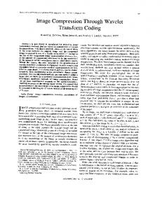
VI. Experimental Results We have implemented the proposed algorithms MHT, DCT and WT. These have been tested for the 1-D, 2-D and color images as follows:
The DTWT splits or decomposes the given signal into components of different scales. Thus, the grounding of wavelet transforms in multiscale decomposition would seem to provide a justification for its use in image compression and analysis in particular, our perception of edges, a crucial image feature, appears to be based on their detectability at multiple scales. Most of the wavelet coefficients in the details have very low values, consequently most of these can be quantized to zero without affecting the perceived quality of the reconstructed image significantly. All wavelet based image compression techniques take advantage of this phenomenon.
Figure I: Compression of 1-D signal (leleccum) using MHT
Algorithm for Compression The algorithm for compression of signals consists of the following steps : 1. The given signal is decomposed into approximate and details coefficients by using the equations.
1 2k
c(k , l) =
d(k,l) =
1 2k
2 k ( l +1)
∫
f ( t )dt …. (XII)
2k l
2k (l+1)
∫
−k
f(t)ψ(2 t −l)dt …. (XIII)
k
2l
The level of decomposition is chosen to be maximum
Figure II: Compression of 1-D signal (leleccum) using DCT
IJCSNS International Journal of Computer Science and Network Security, VOL.7 No.7, July 2007
277
Figure III: Compression of 1-D signal (leleccum) using Haar Wavelet Figure VI: The reconstructed 2-D using DCT.
image(Barbera)
Figure IV: The original 2- D image (Barbera)
Figure VII: The reconstructed 2- D image (Brabera) using WT.
Figure V: The reconstructed (Barbera) using MHT.
2-D
image
Figure VIII: The Original color Image (vinca)
278
IJCSNS International Journal of Computer Science and Network Security, VOL.7 No.7, July 2007
Figure IX: The reconstructed color(vinca)image using MHT.
VII. Comparison of MHT, DCT and WT techniques The Modified Hermite Transform is signal dependent one, signals with Gaussian like envelope could be represented accurately by a few terms in MHT. MHT has no DC component. MHT suffers from computational complexity, i.e generation of unitary matrix of size greater than 256 is difficult to compute, even the computer of 32-bit word length. In MHT, low frequency components are lost in zonal sampling, while high frequency components are lost in DCT. Thus, at low bit rates, transform coded images often exhibit blockings at borders. The DCT is signal independent. The DCT is well suitable for highly correlated signals. The DCT provides a good compromise between information packing ability and computational complexity. It packs most information into the fewest coefficients, and minimizing block like appearance, called blocking artifact, that results when the boundaries between sub images become visible. The Wavelet Transform takes minimum number of coefficients in reconstructing the image and it has least mean square error between the original and reconstructed images compared to the MHT and DCT. The MHT, DCT and WT techniques are applied to various images and their performance is compared and results are shown in Table1. Table I: Comparative Study of various Image Compression Techniques S. No . 1.
Figure X: The reconstructed color image using DCT.
(vinca)
2.
Figure XI: The Reconstructed color image (vinca) using WT.
Name of the Image Leleccum Total No. coefficients No. coefficients used No. coefficients discarded Compression Factor Cameraman Total No. coefficients No. coefficients used No. coefficients discarded Compression Factor
MHT
DCT
WT
of
1024
1024
1024
of
464
83
142
of
560
941
882
2.2120
12.3321
7.2110
of
65536
65536
65536
of
16142
5090
3860
of
49394
60446
61676
4.0599
12.8754
16.9782
IJCSNS International Journal of Computer Science and Network Security, VOL.7 No.7, July 2007
S. No . 3.
4.
5.
Name of the Image Lena Total No. coefficients No. coefficients used No. coefficients discarded Compression Factor Barbera Total No. coefficients No. coefficients used No. coefficients discarded Compression Factor Vinca Total No. coefficients No. coefficients used No. coefficients discarded Compression Factor
MHT
DCT
WT
of
262144
262144
262144
of
12146
4800
3586
of
249998
257344
258558
21.5827
54.6133
73.1020
of
24025
24025
24025
of
10061
5053
260
of
13964
18972
23765
2.3879
4.7574
92.4038
235929 6 235098 2
2359296
235929 6 140353
53314
63381
221894 3
1.0231
1.0276
16.8097
of of of
2295915
VIII. Conclusions and Future Directions We conclude that this work as a whole representation as a significant contribution to the application of wavelet transform to the problems of practical interest in image processing. This work may be extended for Embedded Zero-tree Coding. Using an Embedded code, an encoder can terminate the encoding at any point thereby allowing a target-bit rate .Similarly, the decoder can cease decoding at any point and can produce reconstructions corresponding to all lower rate encoding.
1. IX. References [1] J.Y.Tham, L.Shen, S.L.Lee and H.H.Tan, “A general approach for analysis and applications of Discrete Multiwavelet Transforms”,
279
IEEE Trans. Signal Processing, vol. 48.No.2, February 2000. [2] N. Akansu and Richard A. Haddad, “Multiresolution Signal Decomposition”, Academic press (2001). [3] A.N. Akansu and F.E. Wadas, “On Lapped Orthogonal Transform”, IEEE, Trans, Signal processing. Vol. 40, No. 2, pp.439-443, Feb, 1992. [4] Raghuveer M. Rao and Ajit S. Bopardikar, “Wavelet Transforms Introduction to Theory and Applications”, Addition – Wesley, Reading Massachesetts, 2000. [5] www.wavelet.org.
T.Sreenivasulu Reddy received the B.Tech degree in Electronics and Communication Engineering from Sri Venkateswara University in 1990 and M.Tech degree in Digital Electronics and communication from Karnataka University in 1996. Currently pursuing Ph. D from Jawaharlal Nehru Technological University, India. Research interests include Radar and Image signal Processing. He is working as Associate Professor in the Department of EEE, Sri Venkateswara University, Tirupati, Andhra Pradesh, India. K. Ramani received the B. Tech degree in Electronics and communication Engineering from Sri Venkateswara University in1998 and M. Tech degree in Computer Science and Engineering from Jawaharlal Nehru Technological University, in 2004. Currently pursuing Ph. D from Jawaharlal Nehru Technological University, India. Research interests include Image Processing and Network Security. Dr S Varadarajan received the B.tech degree in Electronics and Commn. Engg. from Sri Venkateswara University in 1987 and M.tech degree from NIT, Warangal. He did his Ph.D in the area of radar signal processing. He is fellow of Institute of Electronics & Telecommunication Engineers (IETE) and member IEEE. Currently working as Associate Professor in the Department of EEE, Sri Venkateswara University, Tirupati, Andhra Pradesh, Tirupati
280
IJCSNS International Journal of Computer Science and Network Security, VOL.7 No.7, July 2007
Dr B.C.Jinaga received the B.E. from Karnataka University, Dharwad, 1971 and M. Tech. from Regional Engineering College, Warangal, 1976.He did his Ph. D. from Indian Institute of Technology, Delhi, 1986. He is fellow of Institution of Engineers (India) and fellow of Institute of Electronics & Telecommunication Engineers. Currently he is working as Rector , JNTU, Hyderabad, India.