Image Processing for Monitoring Diagnostic Devices with. Automated Pipetting. Jun Yeon ... Department of Convergence Software, Hallym University, Korea. 2.
International Journal of Smart Home Vol. 9, No. 8 (2015), pp. 55-62 http://dx.doi.org/10.14257/ijsh.2015.9.8.07
Image Processing for Monitoring Diagnostic Devices with Automated Pipetting Jun Yeon1, 2, Hye-Jeong Song1, 2, Chan-Young Park1, 2, Yu-Seop Kim1, 2, KiBong Nahm3 and Jong-Dae Kim1, 2* 1
Department of Convergence Software, Hallym University, Korea 2 Bio-IT Research Center, Hallym University, Korea 3 Department of Electron Physics, Hallym University, Korea {mauver, hjsong, cypark, yskim01, kbnahm, kimjd}@hallym.ac.kr Abstract
This paper presents an image processing technique for monitoring diagnostic devices with an automated pipetting function. A video camera is employed to inspect whether the device operation, including the tip holder position, the absence of the tip, and the alignment of the holder and the tip, is appropriate. The processing results can be utilized for indicating the overall malfunction of the entire device or for warning that the user has forgotten to load the required tip. The image of the holder and the tip area is converted into a binary image with the fixed threshold obtained during device calibration. A horizontal projection analysis is utilized for robust identification of the tip and the holder area, and a vertical projection analysis is carried out for each area to detect the absence of the tip and the alignment of the tip and holder positions. The camera was added to a commercial diagnostic device, and the processing algorithm was implemented in the main controller of the device. Experimental results show that device monitoring with the proposed image processing technique worked well without failure. Keywords: Automated liquid handler, Image processing, Validation, Projection
1. Introduction Liquid handling is an important part of many experiments related to life sciences, and in particular, it is frequently used in genomic or proteomic research. In general, the liquid handling used in experiments related to life sciences requires accuracy or precision but is a very tedious task requiring a considerable amount of time if carried out manually. Therefore, automation has now become a very important research field [1]. Most of the Automated Liquid Handler (ALH) systems use a conveyor belt to optimize fast inspection of multiple samples at a large hospital. However, because small hospitals find it difficult to apply this system, clinical tests are manually performed or samples are sent to an institute equipped with the appropriate system. To solve these problems, a portable clinical test system using robotic automation has been recently developed. Although its throughput might be smaller than that of a conventional high throughput system, it is relatively flexible, small, and inexpensive. Moreover, such a point-of-care test (POCT) device performs the task of a portable clinical test while being suitable to carry out the selective diagnosis work required at small hospitals [2–3]. In this paper, an image-based validation method is introduced for POCT diagnostic devices with automated pipetting. Many devices require validation for device malfunction or user mistakes in addition to volume verification. The proposed method is applicable to systems that have a holder for mounting a tip. To carry out a diagnosis appropriately, we need to check whether the tip is appropriately inserted, the holder is at the correct position, *
Corresponding Author
ISSN: 1975-4094 IJSH Copyright ⓒ 2015 SERSC
International Journal of Smart Home Vol. 9, No. 8 (2015)
and the tip is aligned with the holder. These are essential validation issues for all devices having an automated pipetting function. Further, we need to notify the user of a device malfunction or a tip installation mistake by processing these validations in the device itself. Recently, because high-performance cameras for smartphones have become inexpensive, if an image processing approach method using such a camera works well, the validation can be conducted with a relatively simple and inexpensive method as compared to the conventional methods using sensors. Since the camera position and lighting are fixed in a device and the lighting condition can be known in advance, a stable function can be implemented without an algorithm error even when a fixed threshold value is employed for the binary conversion of the acquired image or a simple projection technique is applied for the image analysis. In this study, we investigated whether a device can operate without error by applying a simple image processing technology. The experimental test images were prepared by emulating the wrong positions of the tip and the holder. The rest of this paper is organized as follows: We describe the materials and methods in Section 2, discuss the results in Section 3, and present the conclusion in Section 4.
2. Materials and Methods 2.1. Experimental Image Preparation The device used in the experiment is a modified Boditech Med IChroma™ Smart Reader device shown in Figure 1. This device is a scanning device measuring the concentration of the target substance in human blood or blood serum or of other specimens by using a specially designed cartridge. For the diagnosis, a holder where a tip can be inserted is included in addition to the cartridge. The tip and the holder are the most important components in the experiment, and if a problem related to them occurs, the analysis cannot be carried out appropriately. After mounting a reagent and the tip in the cartridge, the user inserts cartridge in the device and the tip is mounted by the tip holder of the pump installed on the device, and the reagent can be sucked in. For an accurate diagnosis, the tip holder has to be placed at the correct position and we need to be check whether the tip is inserted and whether the tip and holder are aligned. To perform these checks, in this study, the camera was mounted in such a way that the pump’s tip holder would be positioned at the middle of the x-axis in the image. For the camera, the PO1150K module, which is a very inexpensive camera module used in smartphones, was used as shown in Figure 2. To emulate the absence of a tip due to a user’s mistake or an incorrect position of the tip or the tip holder due to device malfunction, images were acquired by adjusting the motor in the device. To emulate an absence of the tip, an image was acquired when the tip was not mounted, and for the error of the tip position, images were captured by dislocating the step motor moving the cartridge by a -50–+50 step from the correct position. To emulate the tip holder’s malfunction, several images were captured for a case wherein the tip did not appear on the image and the case wherein it was placed at the correct position, by moving the tip holder position motor.
Copyright ⓒ 2015 SERSC
56
International Journal of Smart Home Vol. 9, No. 8 (2015)
Figure 1. IChroma™ Smart Reader
Figure 2. PO1150K Smart Camera Module 2.2. Image Processing Figure 3 shows the overall flow of the algorithm for obtaining the positions of the tip and the holder. In an image acquired from the camera, since the x-axis position of the tip holder is always constant, the region of interest (ROI) is set in such a way that the tip and holder can be always seen on the basis of this position. Figure 4(a) shows an example of ROI. For an ROI image, the median filter is applied to reduce the noise after converting the image into grayscale. The filtered image is converted into a binary image by using a fixed threshold (Figure 4(b)). Binarization with a fixed threshold was sufficient because the imaging condition such as illumination and background matte finish could be sufficiently controlled through system production. The binary image is vertically separated into the tip part and the holder part. For the tip part, the position is obtained by using a horizontal projection as shown in Figure 5(a), and the holder position is obtained by using a vertical projection as shown in Figure 5(b). The simplest method for obtaining the tip position is the selection of the center of the function support where the profile function has a non-zero value. When there are many noises, this is not a stable method; however, this method can be applied when the imaging condition is good. Similarly, for the holder’s top position, a zero to non-zero transition position of the projection function is selected.
57
Copyright ⓒ 2015 SERSC
International Journal of Smart Home Vol. 9, No. 8 (2015)
Figure 3. Algorithm Flow
(a)
ROI of Tip and Holder
(b) Processed Binary Image
Figure 4. ROI and Binary Image
(a) Horizontal Projection of Tip Part (b) Vertical Projection Of Holder Part
Figure 5. Horizontal Projection of ROI Image for Tip Positioning (a) and Vertical Projection for Holder Positioning (b) 2.3. Data Preparation First, to find out how precise the algorithm is for finding the tip and holder positions, imaging was performed for various tip and holder positions by moving the pertinent stepper motors. The tip center or the holder’s top position was obtained for the acquired images and compared with the position of the stepper motor. The degree of precision was calculating by using a linear relationship between the stepper motor step and the image pixels because the stepper motor position is very precise. Next, to accurately determine the absence of the tip, 75 images were acquired when the tip was present and when it was absent. Some examples of these images are shown in Figure 6. The images taken in the tip presence images were acquired by having a variation
Copyright ⓒ 2015 SERSC
58
International Journal of Smart Home Vol. 9, No. 8 (2015)
of about 8 pixels on the basis of the tip center’s correct position. On the other hand, by always positioning the holder’s top position at the correct position, 25 holder images were acquired each when the holder was present, and when it was absent. Some examples of these acquired images are shown in Figure 7.
(a) Images Acquired In Presence of Tip
(b) Images Acquired In Absence of Tip
Figure 6. Images Acquired in Presence and Absence of Tip
(a) Images Acquired In The Presence Of Holder
(b) Images Acquired In the Absence of Holder
Figure 7. Images Acquired in Presence and Absence of Holder
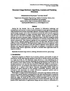
3. Results Figure 8 shows the relationship of the tip stepper motor position and the tip pixel position obtained by image processing. As shown in the figure, these two positions share a very linear relationship. As shown in Table 1, the slope is 0.46, implying a relation of about 2 motor steps per image pixel. The standard deviation of the error in pixel position is 0.79 pixels, which is less than 1 pixel position. Figure 9 shows the relationship of the holder motor position and the holder pixel position obtained by image processing. As shown in Table 1, the relationship between these two positions implies that there are about 5 motor steps per pixel position, and the standard deviation of the error in pixel position is 0.1 pixels. The position of the tip or the holder as obtained by the proposed image processing method is very linear to the pertinent stepper motor’s position (the coefficients of determination are 0.997 and 0.999 for the tip and the holder, respectively).
59
Copyright ⓒ 2015 SERSC
International Journal of Smart Home Vol. 9, No. 8 (2015)
The results of the experiments conducted in the presence and the absence of the tip are summarized in Table 2. As shown in the table, the minimum support length when the tip was present is 54 and the maximum support length in this case is 56. In the case of the absence of the tip, the values were all 0. Therefore, whether the tip was present or not in the ROI could be accurately determined on the basis of support length. The results of the experiments conducted in the absence of the holder are summarized in Table 3, and whether the holder was present or not could be accurately determined on the basis of the start position. From the above results, we concluded that the position information of the tip or the holder could be determined precisely by using simple image processing. This was possible because the imaging condition was highly controllable. The proposed image processing technique exhibited good performance with respect to estimating the tip and holder positions or determining the absence of these components. On the other hand, in the case of the x-axis of the motor, normal operation was confirmed to be performed in the range of -35–+35 steps, and if this range is decided as normal, the tip and the holder can be determined to be normally aligned when their position difference is in the range of 0–70.
Figure 8. Relationship between Tip Stepper Motor Position and Tip Position Obtained By Image Processing
Figure 9. Relationship between Holder Motor Position and Holder Top Position Obtained by Image Processing
Copyright ⓒ 2015 SERSC
60
International Journal of Smart Home Vol. 9, No. 8 (2015)
Table 1. Precision of Tip and Holder Positions Obtained by Image Processing Slope Tip Holder
0.461 0.191
Standard deviation of the error 0.79 0.10
R2 0.993 0.999
Table 2. Experimental Results Obtained in Absence and Presence of Tip Support length Minimu m Maximu m
Images acquired in absence of
Images acquired in presence of tip
0
54
0
59
tip
Table 3. Experimental Results Obtained in Absence and Presence of Holder Start position Minimu m Maximu m
Images acquired in absence of Images acquired in presence of holder holder 0 435 0
436
4. Conclusion In this study, an image-based validation method was introduced for diagnostic devices with automated pipetting, and its performance was verified. By verifying the linear correlation between image pixels and the motor positions, we confirmed that the absence and the alignment of the tip and the holder were able to be checked during the diagnosis by using an image processing technique on the images acquired by the device camera. The proposed simple image processing method using a camera sensor exhibited sufficient performance at a low cost for solving the validation problems that can occur in POCT devices as well. Recently, because of the widespread use of many highperformance camera sensors, this method can be applied to other similar devices. By applying the proposed simple image processing method to a device with a highly controllable imaging condition, user mistakes and/or device malfunction can be prevented by detecting a device failure. Furthermore, if an algorithm for liquid volume is additionally developed, it will be also possible to perform liquid volume verification.
Acknowledgments This work was supported by Bio-IT Research Center, funded by Boditech Med Inc.
References [1] [2] [3]
F. Kong, L. Yuan, Y. F. Zheng and W. Chen “Automatic liquid handling for life science: a critical review of the current state of the art”, J Lab Autom, vol. 17, no. 3, (2012), pp. 169-185. W. S. You, J. J. Park, S. M. Jin, S. M. Ryew and H. R. Choi, “Point-of-care test equipment for Flexible laboratory automation”, J Lab Autom, vol. 19, no. 4, (2014), pp. 403-412. B. Srinivasan and S. Tung, “Development and applications of portable biosensors”, J Lab Autom, (2015), pp. 1-25.
61
Copyright ⓒ 2015 SERSC
International Journal of Smart Home Vol. 9, No. 8 (2015)
Authors Jun-Yeon, He is enrolled in a master degree in Convergence Software in Hallym University. He currently studies for image processing and pattern recognition. His recent interests focus on embedded system and image pattern recognition.
Hye-Jeon g Song, She received the Ph.D. degree in Computer Engineering from Hallym University. She is a Professor in Department of Convergence Software of Hallym University, Korea. His recent interests focus on biomedical system and bioinformatics.
Chan-Young Park, He received the B.S. and the M.S. from Seoul National University and the Ph.D. degree from Korea Advanced Institute of Science and Technology in 1995. From 1991 to 1999, he worked at Samsung Electronics. He is currently a Professor in the Department of Convergence Software of Hallym University, Korea. His research interests are in Bio-IT convergence and sensor networks.
Yu-Seop Kim, He received the Ph.D. degree in Computer Engineering from Seoul National University. He is currently a Professor in the Department of Convergence Software of Hallym University, Korea. His research interests are in the areas of bioinformatics, computational intelligence and natural language processing.
Ki-Bong Nahm, She received the Ph.D. degree in University of Arizona. He is a Professor in Department of Electron Physics of Hallym University. His recent interests focus on biomedical system and bioinformatics
Jong-Dae Kim, He received the M.S. and the Ph.D. degrees in Electrical Engineering from Korea Advanced Institute of Science and Technology, Seoul, Korea, in 1984 and 1990, respectively. He worked for Samsung Electronics from 1988 to 2000 as an electrical engineer. He is a Professor in Department of Convergence Software, Hallym University. His recent interests focus on biomedical system and bioinformatics.
Copyright ⓒ 2015 SERSC
62