In this paper, we present an efficient method to locate the forged parts in a tampered JPEG image. The forged region usually undergoes a different JPEG ...
Image Tampering Localization via Estimating the Non-Aligned Double JPEG compression Lanying Wua, Xiangwei Kong*a, Bo Wanga, Shize Shanga School of Information and Communication Engineering, Dalian University of Technology, Dalian, China, 116024
a
ABSTRACT In this paper, we present an efficient method to locate the forged parts in a tampered JPEG image. The forged region usually undergoes a different JPEG compression with the background region in JPEG image forgeries. When a JPEG image is cropped to another host JPEG image and resaved in JPEG format, the JPEG block grid of the tampered region often mismatches the JPEG block grid of the host image with a certain shift. This phenomenon is called non-aligned double JPEG compression (NA-DJPEG). In this paper, we identify different JPEG compression forms by estimating the shift of NA-DJPEG compression. Our shift estimating approach is based on the percentage of non zeros of JPEG coefficients in different situations. Compared to previous work, our tampering location method (i) performances better when dealing with small image size, (ii) is robust to common tampering processing such as resizing, rotating, blurring and so on, (iii) doesn't need an image dataset to train a machine learning based classifier or to get a proper threshold. Keywords: image forensics, image tampering location, JPEG artifacts, non-aligned double JPEG compression
1. INTRODUCTION With the popularity of easy-to-use image processing tools, image tampering operation becomes an easy trick for ordinary people. It’s difficult to tell whether a given image is tampered by the naked eyes. The trustworthiness of photographs has an essential role in many fields, thus raise the issue of digital image forensics. What’s more, locating tampered region seems to become more and more important, cause it gives straightforward evidence where the tampered regions are. In resent years, various techniques have been proposed to expose tampering, including techniques for detecting artifacts of scaling [1], region duplication [2], etc. Some approaches locate the tampered region due to inconsistency of lighting [3], blurring [4], demosaicing artifacts [5], statistical correlation [6] and so on. Most of these techniques have achieved good performance on uncompressed images. Since JPEG is the most widely used image format, forensic tools designed specifically for JPEG images become indispensable. Paper [7] describes a technique to detect whether the part of an image was initially compressed at a lower quality than the rest of the image. Some other techniques are developed to distinguish between single and double JPEG compression, such as [8][9][10][11]. However, the effective image size or the robustness of these methods is not so satisfying. Besides, most double compression detection methods need a lot of images to train a machine learning based classifier or to get a proper threshold. So, the effectiveness of approaches based on classifier is influenced by the selected image database more or less. For the sake of tampering location, the approach should be robust to post processing operations such as scaling, rotating, blurring which make the tampered region fit well with the background. Besides, the effective image size is supposed to be as small as possible. In this paper, we focus on these two issues. The proposed method locates the tampered region by detecting the presence of non-aligned double JPEG (NA-DJPEG) compression. Here, the aligned double JPEG compression is considered as a specific form of NA-DJPEG compression. In classical image splicing scenario, a region from a JPEG image is pasted on to a host image and then recompressed in JPEG format. The tampered region usually exhibit NA-DJPEG artifacts. If the tampered region undergoes some postprocessing operations or the spliced image is cropped, the tampered region could be considered as singly compressed while the background region will still exhibit NA-DJPEG artifacts. Therefore, our work is based on the hypothesis that the tampered region undergoes different compression from the background region, which happens to most JPEG image forgeries. In comparison to previous work, our method is more stable when image size decreases. It is robust to common Media Watermarking, Security, and Forensics 2013, edited by Adnan M. Alattar, Nasir D. Memon, Chad D. Heitzenrater, Proc. of SPIE-IS&T Electronic Imaging, SPIE Vol. 8665, 86650R © 2013 SPIE-IS&T · CCC code: 0277-786X/13/$18 · doi: 10.1117/12.2003695 SPIE-IS&T/ Vol. 8665 86650R-1 Downloaded From: http://spiedigitallibrary.org/ on 10/27/2015 Terms of Use: http://spiedigitallibrary.org/ss/TermsOfUse.aspx
tampering processing such as resizing, rotating, and blurring and so on. What’s more, the proposed method doesn't require an image dataset to train a classifier or to get a proper threshold. The rest of the paper is organized as follows. In Section 2, we show the underlying clues of JPEG image forgeries. The NA-DJPEG is analyzed and then our method is presented in Section 3. Experiment designation and results are given in Section 4 to show the effectiveness and robustness of the proposed method. In the last section, a discussion and conclusion are provided.
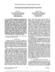
2. JPEG IMAGE TAMPERING CLUES 2.1 Blocking Artifacts by JPEG Compression The Joint Photographic Experts Group (JPEG) has been recommended as a standard compression scheme for continuous-tone still images. Lossy JPEG compression is a block-based compression scheme. During JPEG compressing, image is split into adjacent blocks of 8×8 pixels and each block is dealt separately. Quality factor (QF) is a parameter which determines the quality of JPEG image. It is well-known that JPEG compression will introduce some horizontal or vertical truncations into image. These truncations form an 8×8 grid. In Figure 1(a), the uncompressed image doesn’t have any blocking artifacts. After JPEG compressing, the blocking artifacts emerges. The 8×8 grid of Figure 1(c) is more obvious than Figure 1(b). The smaller the QF is, the more obvious the blocking artifacts is.
(a)
(b)
(c)
Figure 1. JPEG images with different QF: (a) uncompressed image, (b) QF = 70, (c) QF=20.
2.2 JPEG Image Tampering Model Usually, the purpose of image tampering is to interpolate or conceal specific object in original image by copy-pasting. It has been noticed that when the copy-pasting is done, the 8×8 grid of the copied slice (red lines) can hardly be aligned with the block grid of the background region (gray lines), as shown in Figure 2(a).
yb xb
xt yt (a)
(b)
Figure 2. Tampering clues: (a) block artifacts of the tampered and background region before resaving; (b) block artifacts after resaving in JPEG format.
SPIE-IS&T/ Vol. 8665 86650R-2 Downloaded From: http://spiedigitallibrary.org/ on 10/27/2015 Terms of Use: http://spiedigitallibrary.org/ss/TermsOfUse.aspx
The block artifacts after resaving in JPEG format is illustrated in Figure 2(b). The tampered region is misaligned with the final JEPG compression block grid (blue lines) by shift (xt, yt), while the background region is misaligned with the final JEPG compression block grid (blue lines) by shift (xb, yb). If the background region undergoes aligned double JPEG compression, i.e. (xb, yb)=(0, 0), it’s regarded as a specific form of NA-DJPEG. Thus we can utilize the shift to locate the tampered region.
3. TAMPERING LOCATION BASED ON SAM 3.1 Characteristics of JPEG Coefficients JPEG coefficients refer to the DCT coefficients after quantization, which can be extracted directly from the JPEG image file. According to [12], the number of zeros in JPEG coefficients is a critical feature to reflect the JPEG compression quality. Kai San Choi [13] have used the percentages of non-zero JPEG coefficients of the 64 DC/AC components as features to detect the source camera of a given JPEG image. We now analyze the average percentage of zero JPEG coefficients in each component of the 8×8 DCT block. Let m represent the number of DCT blocks , and n( j ) represent the sum of zero JPEG coefficients in the jth component. Then the percentage of zero JPEG coefficients in the jth component is as follows:
p( j )
n( j ) , j 1, 2,..., 64 . m
(1)
and the average percentage of zero JPEG coefficients is:
AVERAGE
64
1
p( j )
64
.
(2)
From Figure 1, we can see that if we compress a BMP image into its JPEG counterparts with different quality factors, the percentages of the zero JPEG coefficients are different, i.e. the larger the quality factor, the better image quality and the less percentage of zero JPEG coefficients. 0.8
AVERAGE
0.6
0.4
0.2
0 75
QF 80
85
90
95
100
Figure 3. The curve of AVERAGE to JPEG compression quality.
3.2 Effects of Non-Aligned Double JPEG Compression In stegonanalysis, there is a classical method to get the “calibrated” image[14]. The stego image is decompressed to the spatial domain, cropped by 4 pixels in each direction, and recompressed as the calibrated counterpart. By cropping, the 8×8 DCT block structure of recompression “does not see” the previous JPEG compression and thus the obtained DCT coefficients are not influenced by previous quantization in the DCT domain. Inspired by [14], we find a way to expose the relationship between AVERAGE and NA-DJPEG compression shift. For a given JPEG image I with quality factor QF, we crop it along a grid shift (x, y) and then compress it again with the same
SPIE-IS&T/ Vol. 8665 86650R-3 Downloaded From: http://spiedigitallibrary.org/ on 10/27/2015 Terms of Use: http://spiedigitallibrary.org/ss/TermsOfUse.aspx
quality factor QF to get image I_shift(x, y). In order to analyse the AVERAGE of image I_shift(x, y) under any shift (x,y), we define the shifted AVERAGE map (SAM) of the given image I as:
SAM( x, y ) AVERAGE(I _ shift ( x, y )), ��0 x 7, �0 y 7 .
(3)
SAM is a 8×8 matrix. For example, an original JPEG image Iori (quality facor QF1) is recompressed by quality factor QF2 as a NA-DJPEG image INA-DJPEG with JPEG grid shift (i, j). Figure 4 shows the SAM of INA-DJPEG with different shifts. We can find that the position of the peak value in SAM coincides with the JPEG grid shift of INA-DJPEG. In Figure 4, the peak position (0, 0) corresponds to aligned double JPEG compressed. Aligned double JPEG compression is treated as a specific form of NA-DJPEG here. Aligned double JPEG compression is a typical double JPEG compression which often occurs in the background region in a tampered image. 01234567
01234567
0 1 2 3 4 5 6 7
0 1 2 3 4 5 6 7
(a)
01234567 0 1 2 3 4 5 6 7
(b)
(c)
Figure 4. The position of peak in SAM for different NA-DJPEG shift. (a) shift (5, 3); (b) shift (1, 6); (c) shift (0, 0).
3.3 Tampering Location Algorithm As described in Section 2.2, the JPEG block grid shift in the tampered region is usually different from the background. This is the key to locate the tampered region. Our proposed tampering location algorithm proceeds in three steps: I. II. III.
Divide the given image into overlapped image blocks in size of N×N with step M. Each image block is denoted by IN×N(x), where x represents the xth block. Compute the SAM for each IN×N(x). Note every IN×N(x) by the position of the AVERAGE peak in the corresponding SAM.
In the first step, we advise that the size of the image blocks N and step M should be integer multiple of 8 to retain the 8×8 block structure caused by JPEG compression. Our algorithm is shown in Figure 5. For better illustration, we use a color map to represent all the shifts. Each block in I is corresponded with a color according to the peak position in the SAM of IN×N(x). Finally we can get the tampering location result of the given image.
-----
(a)
(b)
(c)
(d)
Figure 5. Tampering location procedure: (a) the given tampered image; (b) divide the given image into small blocks with M=N=256; (c) compute SAM for each block; (d) the tampering location result.
Note that there is no classifier used in this algorithm, such as SVM or threshold detector. When training a classifier, the effectiveness of the classifier is dependent on the chosen dataset. In classifier-based cases, the selection of dataset is crucial, and the classifier trained by one dataset usually performances differently on another dataset. No need for
SPIE-IS&T/ Vol. 8665 86650R-4 Downloaded From: http://spiedigitallibrary.org/ on 10/27/2015 Terms of Use: http://spiedigitallibrary.org/ss/TermsOfUse.aspx
tremendous images to get the model (or the threshold) of a classifier means that our method doesn’t rely on a specific dataset, i.e. we don’t need to consider the source dataset for any given image in this paper.
4. EXPERIMENTAL RESULTS In this section, we have conducted different experiments to testify the effectiveness of the proposed method. We selected a dataset containing 300 non-compressed TIFF images with the resolution of 1440×960. These images were taken in different light conditions and have various contents, including portraits, natural scenery, architecture, etc. These 300 TIFF images were compressed in JPEG format with quality factor QF1 = {75, 80, 85, 90, 95}, decompressed, cropped by 64 shifts (i, j) ( 0 £ i £ 7, 0 £ j £ 7 ) separately, and JPEG compressed with quality factor QF2 = {75, 80, 85, 90, 95}. Finally, we generated 300×5×64×5 = 480,000 images to test. First, we analyzed the effects of QF1 and QF2. Due to space limitation, we can not show all the accuracy of the 64 shifts under every QF1 and QF2. So, we computed the accuracy of each condition by average the accuracy of all the 64 shifts. The results are reported in Table 1. The accuracy in the case of QF2 > QF1 is much higher than in the case of QF2 £ QF1 . This is because the block artifacts of the previous compression is weakened after the post compression when QF2 £ QF1 . That is to say, the proposed method is not suitable for detecting the tampered images when QF2 £ QF1 .
Table 1. Average accuracy (%) of the proposed method under different QF1 and QF2 for block size 512×512
75
80
85
75
25.3
68.7
98.7
100
100
80
20.3
27.7
83.7
100
100
85
16
19
28.3
97.7
100
90
21
15.7
19.3
28
100
95
22
19.3
18.3
17
28.7
QF2
QF1
90
95
In order to locate the tampered region more accurately, the effective detecting size of image block is supposed to be as small as possible. In our experiment, the size of the image block ranged from 64 to 512. The accuracy of the proposed method was stable for different size of image block, as illustrated in Figure 6. When the image size decreased to 64×64, our method didn’t change much while the method in [15] dropped to 61.7%. 100 90
method in [15] our method
accuacy(%)
80 70 60 50 40 30 20 10 0
64
96 128 160 192 224 256 288 320 352 384 416 448 480 512 block size
Figure 6. Comparison between our method and the method in [15] when QF1=85 and QF2=95.
SPIE-IS&T/ Vol. 8665 86650R-5 Downloaded From: http://spiedigitallibrary.org/ on 10/27/2015 Terms of Use: http://spiedigitallibrary.org/ss/TermsOfUse.aspx
Let us see how the proposed method performances in practical situations. Take a tampered image for example. In Figure 7(a), the given image was tampered by pasting a drawing to the wall, and resaved by quality factor 95 afterwards. The detection size N was set to 128 with the step M = 64. Figure 7(d) shows the tampering location result of our method. Most region of the result image is black, referring to the shift (0, 0), i.e. the aligned double compressed region which is treated as the non tampered region. So, the black part corresponds to the background of the given image. Besides the black part, we can also see colorful part in the result image, which located the tampered region of the given image. In Figure 7(d), the proposed method located the tampered region properly, while the result of method in [8] (Figure 7(b)) and [15] (Figure 7(b)) were less clear.
_I :
(a)
(b)
(c)
(d)
Figure 7. (a) tampered image with no post processing; (b) result of [8]; (c) result of [15]; (d) result of the proposed method.
In order to cheating the human eyes, the tampering region often goes through some post-procession such as resizing, rotating, and blurring and so on. In Figure 8(a), the drawing was shrinked and rotated before pasting to the wall. Afterwards, the edge of the drawing was blurred. Our method proved to be effective in this situation, as demonstrated in Figure 8(d). i
,r:.,,ti ,
(a)
(b)
(c)
(d)
Figure 8. (a) tampered region with post-procession; (b) result of [8]; (c) result of [15]; (d) result of the proposed method.
After tampering, the forger may crop the region of interest in the image and resave it in JPEG format. In this situation, the tampered region still undergoes a NA-DJPEG compression different with the background. In this case, the approach in [8] was invalid while our method still worked, as illustrated in Figure 9. However, the result was not as satisfying as the results above. Because in the case of shift (0, 0), the detection accuracy is a little higher than in the case of other shifts. i
(a)
.
(b)
ir,.,
:,
(c)
(d)
Figure 9. (a) tampered image with background cropped; (b) result of [8]; (c) result of [15]; (d) result of the proposed method.
SPIE-IS&T/ Vol. 8665 86650R-6 Downloaded From: http://spiedigitallibrary.org/ on 10/27/2015 Terms of Use: http://spiedigitallibrary.org/ss/TermsOfUse.aspx
5. CONCLUSION In this paper, we presented an efficient method to locate the forged part in a tampered JPEG image. This work is done under the hypothesis that the tampered region undergoes a NA-DJPEG compression different with the host image region, which happens to most JPEG image forgeries. The proposed method doesn’t need a classifier like a machine learning model or a threshold detector, which makes the proposed method independent on the image dataset. The experimental results have demonstrated the effectiveness of the proposed method. Compared to the previous work in [15], our approach performances better when dealing with small blocks. This is important to precisely locate the tampered region. If the tampered image is cropped before resaving to JPEG format, the method in [8] can not work while our method shows a satisfying result. What’s more, the proposed method is robust to common tampering processing such as resizing, rotation, blurring and so on. Unfortunately, our method loses effectiveness when QF1 > QF2. We will try to solve this problem in future work.
ACKNOWLEDGMENT Thanks to the support of National Natural Science Foundation of China under Grants No. 61172109 and No. 60971095 f or this paper, and also the Fundamental Research Funds for the Central Universities.
REFERENCES [1] Matthias Kirchner, “Fast and reliable resampling detection by spectral analysis of fixed linear predictor residue,” Proceedings of the 10th ACM workshop on Multimedia and security, 11-20 (2008). [2] Sevinc Bayram, Husrev T. Sencar and Nasir Memon, “An Efficient and Robust Method for Detecting CopyMove Forgery,” IEEE International Conference on Acoustics, Speech, and Signal Processing, 1053-1056 (2009). [3] Eric Kee, Hany Farid, “Exposing Digital Forgeries from 3-D Lighting Environments,” Workshop on Information Forensics and Security, 1-6 (2010). [4] Pravin Kakar, Sudha Natarajan, Wee Ser, “Exposing Digital Image Forgeries by Detecting Discrepancies in Motion Blur,” IEEE Transactions on Multimedia 13(3), 443-452 (2011). [5] Ahmet Emir Dirik, Nasir Memon, “Image Tamper Detection Based on Demosaicing Artifacts,” IEEE International Conference on Image Processing, 1509-1512 (2009). [6] Hong Cao, Alex C. Kot, “Measuring the Statistical Correlation Inconsistencies in Mobile Images for Tamper Detection,” Transactions on Dating Hiding and Multimedia Security 7, 63-81 (2012). [7] H. Farid, “Exposing digital forgeries from JPEG ghosts,” IEEE transactions on Information Forensics and Security 4(1), 154-160(2009). [8] T Pevny, J Fridrich, “Detection of Double-Compression in JPEG Images for Applications in Steganography,” IEEE transactions on Information Forensics and Security 3(2), 247-258 (2008). [9] Fangjun Huang, Jiwu Huang, Yun Qing Shi, “Detecting Double JPEG Compression With the Same Quantization Matrix,” IEEE Transactions on Information Forensics and Security 5(4), 848-856 (2010). [10] Xiaoying Feng, Gwenael Doerr, “JPEG Recompression Detection,” Proc. SPIE 7541, 75410J (2010). [11] Chunhua Chen, Shi Y.Q, Wei Su, “A Machine Learning Based Scheme for Double JPEG Compression Detection,” 19th International Conference on Pattern Recognition, 1-4 (2008). [12] J.-Y. Lee and H. W. Park, “A rate control algorithm for DCT-based video coding using simple rate estimation and linear source model,” IEEE Transactions on Circuits and Systems for Video Technology 15(9), 1077–1085 (2005). [13] Kai San Choi, Edmund Y. Lam, Kenneth K.Y. Wong, “Source Camera Identification by JPEG Compression Statistics for Image Forensics,” IEEE Region 10 Conference, 1-4 (2006). [14] J.Fridrich, “Feature-Based Steganalysis for JPEG Images and its Implications for Future Design of Steganographic Schemes,” Proc. 6th Information Hiding Workshop, 67-81 (2004). [15] Tiziano Bianchi, Alessandro Piva, “Detection of Non-Aligned Double JPEG Compression Based on Integer Periodicity Maps,” IEEE transactions on Information Forensics and Security. 7(2), 842-848 (2012).
SPIE-IS&T/ Vol. 8665 86650R-7 Downloaded From: http://spiedigitallibrary.org/ on 10/27/2015 Terms of Use: http://spiedigitallibrary.org/ss/TermsOfUse.aspx