Imaging through aberrating media by computational ghost imaging ...
Recommend Documents
Feb 4, 2013 - arXiv:1212.3253v2 [physics.optics] 4 Feb 2013. Computational ... tational ghost imaging and an imaging laser radar for this application [14, 15].
Oct 4, 2011 - ... shown schematically in Fig. 1 [13]. Pseu- dothermal ghost imaging can be described quantitatively. arXiv:1110.0845v1 [quant-ph] 4 Oct 2011 ...
temporal ghost imaging system over a single optical fiber is derived, which is a ... light source bandwidth, resulting in a significantly distorted ghost image.
Abstract. Computational ghost imaging is a robust and compact system that has drawn wide attentions over the last two decades. Multispectral imaging ...
Introduction to computational ghost imaging. Computational ghost imaging (GI) is an alternative technique to conventional imaging and removes the need for a.
Feb 19, 2013 - immersed in turbid media via differential ghost imaging (DGI) in a backscattering configuration. The method has been applied, for the first time ...
May 26, 2011 - 1Department of Physics and Astronomy, University of Rochester, Rochester, New York ... 5Department of Ele
Oct 17, 2016 - [11] C. Q. Zhao, W. L. Gong, M. L. Chen, E. R. Li, H. Wang,. W. D. Xu, and S. S. ... [17] B. Sun, M. P. Edgar, R. Bowman, L. E. Vittert, S. Welsh, A. Bowman ... man, R. G. Dall, K. G. H. Baldwin, and A. G. Truscott, ... [24] W. Chen an
Jun 25, 2010 - We present a new technique, differential ghost imaging (DGI), which ... than the one achievable with the conventional ghost imaging (GI) ...
Oct 17, 2016 - path integral theory. It is found that ghost imaging with thermal fermions can be simulated by ghost imaging with thermal bosons and classical ...
Jun 25, 2010 - We present a new technique, differential ghost imaging (DGI), which dramatically enhances ..... Company, Greenwood Village, CO, 2006), pp.
Jan 23, 2018 - Abstract: Single-pixel imaging uses a single-pixel detector, rather than a ... It provides advantages for applications such as multi-wavelength,.
High quality computational ghost imaging using multi-fluorescent screen. Hossein Ghanbari-Ghalehjoughi,1,2 Sohrab Ahmadi-Kandjani,2,* and Mansour ...
Sep 29, 2009 - behind G(2)( Ïo, Ïi) made ghost imaging so special. ... through a convex lens of 400mm focal length and illuminates a chosen aperture (mask).
bandwidth and the near-field resolution of the reproduced image, ... field bandwidth of PDC. ...... in fact gives an unlimited bandwidth as when a spatial average ...
Dec 31, 2016 - Ghost imaging allows to image an object without directly seeing this object. ... Here, we improve significantly the resolution of ghost imaging.
A novel technique for polarization-multiplexing ghost imaging is proposed to simultaneously obtain multiple polarimetric information by a single detector. Here ...
Sep 28, 2006 - Honglin Liu,â Jing Cheng, Yanfeng Bai, and Shensheng Han. Key Laboratory for Quantum Optics and the Center for Cold Atom Physics of ...
Mar 22, 2013 - arXiv:1301.4390v3 [physics.optics] 22 Mar 2013 ... The advantages of both differential GI and time-correspondence GI are combined, plus less ...
Sep 29, 2009 - ... index or phase disturbance in the optical path has no influence to the type-two ghost image. 1. arXiv:0805.1166v5 [quant-ph] 29 Sep 2009 ...
Mar 1, 2014 - For conventional ghost imaging (GI) systems, the object image is obtained based on the reflective or transmissive character of the object.
Mar 23, 2016 - mean free path lt) are comparable with the bandwidth of common laser ... of 150 nm diameter are used to monitor the SHG enhancement ...
Imaging of an object hidden in random scattering media is achieved with cw broadband (white-light) inter- ferometry. The light source is an inexpensive, ...
Feb 24, 2015 - niques to synthesize and make sense of these âbig dataâ experiments. As ... analysis stages can be executed on the scale of minutes, which ...
Imaging through aberrating media by computational ghost imaging ...
Jan 10, 2014 - aberrating media by computational ghost imaging (CGI). An incoherent LED light source is used instead of the common pseudothermal light ...
COL 12(1), 011102(2014)
CHINESE OPTICS LETTERS
January 10, 2014
Imaging through aberrating media by computational ghost imaging with incoherent light
ÜÕ), Jianhong Shi (ê ) , Hu Li (o m), and Guihua Zeng (QBu)
Yinzuo Zhang (
∗
State Key Laboratory of Advanced Optical Communication Systems and Networks, Key Lab on Navigation and Location-based Service, Department of Electronic Engineering, Shanghai Jiao Tong University, Shanghai 200240, China. ∗ Corresponding author: [email protected] Received November 4, 2013; accepted November 28, 2013; posted online January 8, 2014 We demonstrate a series of experiments on imaging through both stationary aberrating media and moving aberrating media by computational ghost imaging (CGI). An incoherent LED light source is used instead of the common pseudothermal light source (laser light passing through a rotating ground glass). A digital micromirror device is used as a simple spatial light modulator to perform CGI. Moreover, a digital filtering method is introduced to improve imaging quality through moving aberrating media. This imaging modality may have potential applications in medicine and astronomy. OCIS codes: 110.0113, 110.1758. doi: 10.3788/COL201412.011102.
Imaging methods through aberrating media are highly interesting to biologists and astronomists, who are becoming closer to achieving this goal using various techniques. These techniques include optical phase conjugation[1,2] , spatial and temporal wavefront shaping[3−5] , and turbid lens imaging[6,7]. However, these methods require either complex experimental setups (e.g., femtosecond laser, electron multiplying charge-coupled device (EMCCD), etc.) or complicated numerical solution procedures. Drastic alterations in aberrating media are also forbidden in these methods. Different from classical imaging mechanisms, ghost imaging (GI)[8−13] is a novel imaging technique because of its second-order intensity correlation. After traditional GI (TGI), many improvements have been made. In terms of algorithm, differential GI (DGI)[14] and normalized GI (NGI)[15] have been proposed because of the better imaging performance than TGI. In terms of system complexity, computational GI (CGI)[16] that requires only one optical path is theoretically proposed by Jerey H. Shapiro in 2008, which requires only one optical path. Then, Silberberg et al. first utilized a spatial light modulator (SLM) to experimentally investigate CGI[17] in 2009. Recently, Sun et al.[18] used CGI to study object authentication and three-dimensinal computational imaging, respectively. Inspired by Gong’s work[19] , we investigate imaging in this letter imaging through both stationary and moving aberrating media through CGI with TGI algorithm (DGI algorithm has similar performance to TGI when the object is highly absorbing). A digital filtering method is also introduced to improve the image quality of certain moving aberrating medium situations. Recent work by Goy et al. demonstrated imaging in focusing Kerr media using digital holography and digital reverse propagation of the wave[20], which showed similar twopaths optical structure to GI except for different algorithms. The experimental schematic is shown in Fig. 1(a). A beam of incoherent light emitted by a cold white 1671-7694/2014/011102(3)
LED (MCWHL5 Thorlabs, USA), is first irradiated onto a digital micromirror device (DMD) consisting of 1024 × 768 independent addressable units. Each unit is a 13.68 × 13.68-(µm) micromirror with an adjustable angle of ± 12◦ and a maximum flipping frequency of 20 kHz. Then, the modulated light goes through a thin lens L1 with focal length f1 = 10 cm, and the distance from the DMD to L1 is Z = 16 cm. A reflection-type object (school badge of Shanghai Jiao Tong University; 1.3 × 1.3 (cm); Fig. 1(b)) is placed at a distance of L = 42 cm from the DMD to satisfy the Gaussian thin-lens equation 1/f1 ≈ 1/(L − Z) + 1/Z. After being reflected from the badge, the signal light then goes through an aberrating medium (a 2-mm-thick ground glass), and another lens L2 collects the scattered light onto a “bucket” detector simulated by a charge-coupled device (CCD). The modulation speed of DMD is set to 106 Hz (which could be higher using only a part of the micro-mirrors), synchronous with the CCD acquisition rate. During each acquisition, a pre-calculated random binary image of 1024 × 768 pixels (Fig. 1(c)) is first sent to the DMD where the minimum independent region is realized by 4 × 4 pixels. Figure 1(d) shows the image directly captured by the CCD behind the ground glass. In Fig. 1(d), we cannot recognize any information on the badge. The imaging result can be retrieved by g (x, y) = h(b (n) − hb (n)i) (rn (x, y) − hrn (x, y)i)i = hb (n) rn (x, y)i − hb (n)i hrn (x, y)i , (1) where h·i denotes an ensemble average over N times of acquisitions; b (n) and rn (x, y) (1 6 n 6 N ) represent the nth bucket detecting value (by summing over the CCD’s pixel values) and the nth reference path’s spatial pattern, respectively. Some other value can also be taken to represent b (n) to obtain the imaging result such as the central value or other value by summing over small blocks of the recorded image through CCD. Imaging results with different number of acquisitions are shown in
011102-1
c 2014 Chinese Optics Letters
COL 12(1), 011102(2014)
CHINESE OPTICS LETTERS
January 10, 2014 ∆T 2
Fig. 1. (Color online) (a) Schematic of imaging through aberrating media by CGI. (b) Imaging target (a school badge of Shanghai Jiao Tong University). (c) Random image sent to DMD. (d) Image captured by CCD behind the ground glass.
Fig. 2. (Color online) Reconstructed images of school badge of Shanghai Jiao Tong University through aberrating media (L=42 cm) from DMD by CGI. Ghost imaging results corresponding to different number of acquisitions: (a) N =3000, (b) N =30000, and (c) N =120000. (d) Enlarged image of parts of (c) marked in red.
Fig. 2. The image quality clearly improves with the number of acquisitions intuitively increasing. In terms of transverse resolution, based on the van Cittert-Zernike theorem, it is determined by transverse coherence length (i.e., the speckle size[17] ) of the light field. Specific to CGI with DMD, the resolution is mainly determined by two elements: the minimum independent region of preset random image and the magnifying effect of lens. In the above experiment, we choose 4 × 4 micromirrors with an edge length of a = 4 × 13.68 = 54.72 µm as the minimum independent region. Thus, the transverse resolution δx can be recognized as an approximation of δx (L = 42 cm)=a × (L−Z) /Z ≈ 90 µm. Two parallel lines marked in red in the central part of the badge (Fig. 2(c)) are well resolved from Fig. 2(d). The vertical distance between the double lines is approximately 200 µm, larger than δx . Thus, we can detect objects with more details using this imaging system. Regarding signal-to-noise ratio (SNR), it can be expressed
N min as SNR= N , where T 2 and ∆Tmin denote the avs T2 erage quadratic transmission function of the object and the minimum variation of the object transmission function, respectively[14] ; Ns denotes the average number of speckles reflecting from (or transmitting through) the ob= Abeam , where ject and can be derived from Ns = AAbeam 2 δx coh Abeam denotes the beam area in the position of the object; δx and Acoh (Acoh = δx2 ) denote the speckle size also in the position of the object. In this letter, ∆Tmin ≈ 0.5, Abeam ≈ 275 mm2 , and δx ≈ 90 µm; thus, Ns ≈ 34 000 speckles. After some calculations, the SNR values corresponding to N = 3000, 30000, and 120000, are 1.68, 10.06, and 20.14. According to the analysis above, we can improve the resolution of this imaging system by reducing the minimum independent region of the preset random image to 2 × 2 or 1 × 1 pixels, but this process may cause a decrease in SNR. Thus, a tradeoff clearly exists between resolution and SNR[17] . We can also improve the image SNR by simply taking more acquisitions. The above experiment mainly focuses on the situation of stationary aberrating media. However, image quality may be dramatically affected in cases of moving aberrating media such as body fluid flow in medical inspections and atmospheric dust movements in astronomical observations. Thus, we perform another experiment of rotating the ground glass (driven by a programmable stepper motor) during detection to simulate imaging through moving aberrating media. The angular velocity ω is set 1 π and 13 π rad/s. The experto be changeable between 24 imental setup is the same as in Fig. 1(a). The DMD modulation speed and CCD acquisition rate remain at 106 Hz (frames/s). Figure 3(2)(c) shows the imaging result through a rotating ground glass with N = 60 000 acquisitions, whereas Fig. 3(1)(c) is the result of imaging through a stationary ground glass. Figure 3(2)(c) reveals that almost all details of the badge are submerged in the background compared with Fig. 3(1)(c). The reason for this phenomenon is that the original bucket detecting values are polluted by noises aroused by rotatng ground glass. However, considering the original bucket detecting values and the fact that noises may have different distributions in the Fourier-transform domain (or other domains), we may be able to improve the image quality by suppressing noise components. In the present letter, we propose a digital filtering method to reduce the negative effects of moving aberrating media. The analysis process is demonstrated as follows:
B(k) = FFT(b(n)), ˜ B(k) = H(k)B(k),
(2)
˜b(n) = IFFT(B(k)), ˜
(4)
(3)
where b(n) and ˜b(n) (1 6 n 6 N ) denote sequences of bucket detecting values before and after filtering; H(k) (1 6 k 6 N ) denotes a frequency-selective filter with which we could suppress the noise frequency components; FFT and IFFT denote the Fast Fourier-transformation and its inverse transformation, respectively. By substituting ˜b(n) to Eq. (1), we get the imaging result after filtering g˜(x, y) = h˜b(n)rn (x, y)i − h˜b(n)i hrn (x, y)i.
011102-2
COL 12(1), 011102(2014)
CHINESE OPTICS LETTERS
January 10, 2014
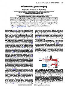
as a simple example but without loss of generality of imaging through moving aberrating media. In conclusion, compared with conventional optical imaging, imaging through stationary aberrating media can achieve improved image quality by CGI. Furthermore, in terms of imaging through moving aberrating media, the digital filtering technique helps reduce the negative effects of moving media as long as the noises introduced by moving media can be distinguished in the Fourier-transform domain (or other domains). These experiments use only a set of simple experimental apparatuses: a simple and low-cost LED light source, a convenient binary SLM DMD and an ordinary CCD. Moreover, we introduce a simple, mature, and adaptive digital filtering algorithm that shows wide range of applications in industrial control and voice processing to improve the image quality of imaging through moving aberrating media. The CGI modality with digital filtering technique may have potential applications in clinical monitoring and astronomical observations. Fig. 3. (Color online) Comparisons of three cases in the experiment of imaging through aberrating media. From top to bottom, row (1) is the stationary ground glass case, row (2) is the rotating ground glass case, and row (3) is the rotating ground glass with digital filtering case. From left to right, column (a) is the distribution of bucket detecting values corresponding to the three cases, respectively; column (b) is the FFT result of bucket detecting values of the three cases; column (c) is imaging result of the three cases.
To verify the availability of the digital filtering method based on Eqs. (2)−(4), we compare the three cases shown in Fig. 3. The first case is a stationary ground glass, the second is a rotating ground glass, and the third is a rotating ground glass with digital filtering. Figure 3(1)(a) shows the fluctuation distribution of N = 60 000 bucket detecting values (denoted by b1 (n), 1 6 n 6 N ) of the first case, and Fig. 3(2)(a) shows that of the second case (denoted by b2 (n), 1 6 n 6 N ). The standard deviation of b1 (n) is 5.1404 ×10⁵ smaller than that of b2 (n) (1.1946 ×10⁶ ), which obviously results from the noise brought in by the rotating ground glass. Figures 3(1)(b) and 3(2)(b) show the FFT results of b1 (n) and b1 (n), denoted by B1 (k) and B1 (k), respectively. Figures 3(1)(b) and 3(2)(b) show that B1 (k) is very uniform compared with most of the frequency components, whereas B2 (k) shows richness (peaks) in some specific frequency components (Fig. 3(2)(b)). Then we use a low-cut digital filter, denoted by H(k) (red line in Fig. 3(2)(b)), to suppress these frequency components. The result after filtering, ˜2 (k), is shown in Fig. 3(3)(b) (more unidenoted by B form than Fig. 3(2)(b)). Figure 3(3)(a) shows the IFFT ˜2 (k), denoted by ˜b2 (n). Column (c) in Fig. result of B 3 shows reconstructed images of the three cases where in terms of image quality, Fig. 3(1)(c) is intuitively the best, Fig. 3(2)(c) is the worst, and Fig. 3(3)(c) shows markedly improved quality compared with Fig. 3(2)(c). The SNR values of the three cases in Fig. 3 are 16.58, 2.13, and 6.12. Therefore, based on intuition and quantitative analyses, the method of digital filtering helps improve the quality of imaging through moving aberrating media as long as the noise introduced by moving media can be distinguished in the Fourier domain (or other domains). This experiment is demonstrated just
This work was supported by the National Natural Science Foundation of China under Grant Nos. 60970109 and 61170228. References 1. E. N. Leith and J. J. Upatnieks, J. Opt. Soc. Am. 56, 523 (1966). 2. Z. Yaqoob, D. Psaltis, M. S. Feld, and C. Yang, Nat. Photon. 2, 110 (2008). 3. O. Katz, E. Small, Y. Bromberg, and Y. Silberberg, Nat. Photon. 5, 372 (2011). 4. A. P. Mosk, A. Lagendijk, G. Lerosey, and M. Fink, Nat. Photon. 6, 283 (2012). 5. G. Lerosey, J. de Rosny, A. Tourin, and M. Fink, Science 315, 1120 (2007). 6. Y. Choi, M. Kim, C. Yoon, T. D. Yang, K. J. Lee, and W. Choi, Opt. Lett. 36, 4263 (2011). 7. Y. Choi, T. D. Yang, C. Fang-Yen, P. Kang, K. J. Lee, R. R. Dasari, M. S. Feld, and W. Choi, Phys. Rev. Lett. 107, 023902 (2011). 8. T. B. Pittman, Y. H. Shih, D. V. Strekalov, and A. V. Sergienko, Phys. Rev. A 52, R3429 (1995). 9. R. S. Bennink, S. J. Bentley, and R. W. Boyd, Phys. Rev. Lett. 89, 113601 (2002). 10. A. Gatti, E. Brambilla, M. Bache, and L. A. Lugiato, Phys. Rev. Lett. 93, 093602 (2004). 11. R. S. Bennink, S. J. Bentley, R. W. Boyd, and J. C. Howell, Phys. Rev. Lett. 92, 033601 (2004). 12. B. Cao, C. Zhang, and P. Ou, Chin. Opt. Lett. 9, 081102 (2011). 13. D. Duan and Y. Xia, Chin. Opt. Lett. 10, 031102 (2012). 14. F. Ferri, D. Magatti, L. A. Lugiato, and A. Gatti, Phys. Rev. Lett. 104, 253603 (2010). 15. B. Sun, S. S. Welsh, M. P. Edgar, J. H. Shapiro, and M. J. Padgett, Opt. Express 20, 16892 (2012). 16. J. H. Shapiro, Phys. Rev. A 78, 061802 (2008). 17. Y. Bromberg, O. Katz, and Y. Silberberg, Phys. Rev. A 79, 053840 (2009). 18. B. Sun, M. P. Edgar, R. Bowman, L. E. Vittert, S. Welsh, A. Bowman, and M. J. Padgett, Science 340, 844 (2013). 19. W. Gong and S. Han, Opt. Lett. 36, 394 (2011). 20. A. Goy and D. Psaltis, Photon. Res. 1, 96 (2013).