Line Integral. Convolution (LIC) is a new technique that possesses many of these
properties. Its generality allows for the introduction of a com- pletely new family ...
Imaging Vector Fields Using Line Integral Convolution Brian Cabral Leith (Casey) Leedom* Lawrence Livermore National Laboratory
ABSTRACT Imaging vector fields has applications in science, art, image processing and special effects. An effective new approach is to use linear and curvilinear filtering techniques to locally blur textures along a vector field. This approach builds on several previous texture generation and filtering techniques[8, 9, 11, 14, 15, 17, 23]. It is, however, unique because it is local, one-dimensional and independent of any predefined geometry or texture. The technique is general and capable of imaging arbitrary two- and three-dimensional vector fields. The local one-dimensional nature of the algorithm lends itself to highly parallel and efficient implementations. Furthermore, the curvilinear filter is capable of rendering detail on very intricate vector fields. Combining this technique with other rendering and image processing techniques — like periodic motion filtering — results in richly informative and striking images. The technique can also produce novel special effects. CR categories and subject descriptors: I.3.3 [Computer Graphics]: Picture/Image generation; I.3.7 [Computer Graphics]: Three-Dimensional Graphics and Realism; I.4.3 [Image Processing]: Enhancement. Keywords: convolution, filtering, rendering, visualization, texture synthesis, flow fields, special effects, periodic motion filtering. 1. INTRODUCTION Upon first inspection, imaging vector fields appears to have limited application — confined primarily to scientific visualization. However, much of the form and shape in our environment is a function of not only image intensity and color, but also of directional information such as edges. Painters, sculptors, photographers, image processors[16] and computer graphics researchers[9] have recognized the importance of direction in the process of image creation and form. Hence, algorithms that can image such directional information have wide application across both scientific and artistic domains. Such algorithms should possess a number of desirable and sometimes conflicting properties including: accuracy, locality of calculation, simplicity, controllability and generality. Line Integral Convolution (LIC) is a new technique that possesses many of these properties. Its generality allows for the introduction of a com* Authors’ current e-mail addresses are:
[email protected] and
[email protected].
pletely new family of periodic motion filters which have wide application (see section 4.1). It represents a confluence of signal and image processing and a variety of previous work done in computer graphics and scientific visualization. 2. BACKGROUND There are currently few techniques which image vector fields in a general manner. These techniques can be quite effective for visualizing vector data. However, they break down when operating on very dense fields and do not generalize to other applications. In particular, large vector fields (512x512 or greater) strain existing algorithms. Most vector visualization algorithms use spatial resolution to represent the vector field. These include sampling the field, such as with stream lines[12] or particle traces, and using icons[19] at every vector field coordinate. Stream lines and particle tracing techniques depend critically on the placement of the “streamers” or the particle sources. Depending on their placement, eddies or currents in the data field can be missed. Icons, on the other hand, do not miss data, but use up a considerable amount of spatial resolution limiting their usefulness to small vector fields. Another general approach is to generate textures via a vector field. Van Wijk’s spot noise algorithm[23] uses a vector field to control the generation of bandlimited noise. The time complexity of the two types of implementation techniques presented by Van Wijk are relatively high. Furthermore the technique, by definition, depends heavily on the form of the texture (spot noise) itself. Specifically, it does not easily generalize to other forms of textures that might be better suited to a particular class of vector data (such as fluid flow versus electromagnetic). Reaction diffusion techniques[20, 24] also provide an avenue for visualizing vector fields since the controlling differential equations are inherently vector in nature. It is possible to map vector data onto these differential equations to come up with a vector visualization technique. Here too however, the time complexity of these algorithms limit their general usefulness. Three-dimensional vector fields can be visualized by threedimensional texture generation techniques such as texels and hypertextures described in [11, 15]. Both techniques take a texture on a geometrically defined surface and project the texture out some distance from the surface. By definition these techniques are bound to the surface and do not compute an image for the entire field as is done by Van Wijk[23]. This is limiting in that it requires a priori knowledge to place the surface. Like particle streams and vector streamers these visualization techniques are critically dependent on the placement of the sampling surface. The technique presented by Haeberli[9] for algorithmicly generating “paintings” via vector-like brush strokes can also be thought of as a vector visualization technique. Crawfis and Max[5]
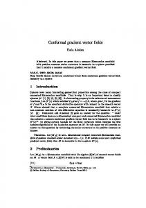
describe a three-dimensional variation on this in which blurred cylinders represent three-dimensional brush strokes whose directions and colors are controlled by a three-dimensional vector field. Both techniques represent a conceptual extension of traditional icon placement, where the icons are more sophisticated shapes. However, these techniques break down as the density of the field increases since they require spatial resolution to work. What is needed is a technique that can image dense vector fields, is independent of both predefined sampling placement constraints and texture generation techniques and can work in two and three dimensions. Such a technique would be very general and have wide application. 3. DDA CONVOLUTION One approach is a generalization of traditional DDA line drawing techniques[1] and the spatial convolution algorithms described by Van Wijk[23] and Perlin[14]. Each vector in a field is used to define a long, narrow, DDA generated filter kernel tangential to the vector and going in the positive and negative vector direction some fixed distance, L. A texture is then mapped one-to-one onto the vector field. The input texture pixels under the filter kernel are summed, normalized by the length of the filter kernel, 2L, and placed in an output pixel image for the vector position. Figure 1, illustrates this operation for a single vector in a field. This effectively filters the underlying texture as a function of the vector field. The images in figure 2 are rendered using the DDA convolution algorithm. On the left is a simple circular vector field; to its right is the result of a computational fluid dynamics code. The input texture image in these examples is white noise. Although the description above implies a box filter, any arbitrary filter shape can be used for the filter convolution kernel. It is important to note that this algorithm is very sensitive to symmetry of the DDA algorithm and filter. If the algorithm weights the forward direction more than the backward direction, the circular field in figure 2 appears to spiral inward implying a vortical behavior that is not present in the vector field. 3.1 LOCAL FIELD BEHAVIOR The DDA approach, while efficient, is inherently inaccurate. It assumes that the local vector field can be approximated by a
Figure 2: Circular and turbulent fluid dynamics vector fields imaged using DDA convolution over white noise.
straight line. For points in vector fields where the local radius of curvature is large, this assumption is valid. However, where there are complex structures smaller than the length of the DDA line, the local radius of curvature is small and is not well approximated by a straight line. In a sense, DDA convolution renders the vector field unevenly, treating linear portions of the vector field more accurately than small scale vortices. While this graceful degradation may be fine or even desirable for special effects applications, it is problematic for visualizing vector fields such as the ones in figure 2, since detail in the small scale structures is lost. Van Wijk’s spot noise algorithm[23] also suffers from this problem since the spots are elliptically stretched along a line in the direction of the local field. If the ellipse major axis exceeds the local length scale of the vector field, the spot noise will inaccurately represent the vector field. An accurate measure of local field behavior would require a global analysis of the field. Such techniques currently do not exist for arbitrary vector fields, would most likely be expensive to calculate[13] and are an area of active research[7]. 4. LINE INTEGRAL CONVOLUTION The local behavior of the vector field can be approximated by computing a local stream line that starts at the center of pixel (x, y) and moves out in the positive and negative directions.1 The forward coordinate advection is given by equation (1). P 0 = ( x + 0.5, y + 0.5 )
Vector field
Pi = Pi − 1 +
∆s i − 1
(1)
∞if V|| e ( top, y ) Pc − Pc