ARTICLE IN PRESS Computer-Aided Design (
)
–
Contents lists available at ScienceDirect
Computer-Aided Design journal homepage: www.elsevier.com/locate/cad
Immersive modeling system (IMMS) for personal electronic products using a multi-modal interface Yong-Gu Lee a , Hyungjun Park b , Woontaek Woo c , Jeha Ryu a , Hong Kook Kim c , Sung Wook Baik d , Kwang Hee Ko a , Han Kyun Choi a , Sun-Uk Hwang a , Duck Bong Kim a , HyunSoo Kim a , Kwan H. Lee a,∗ a
Department of Mechatronics, Gwangju Institute of Science and Technology(GIST), Gwangju, South Korea
b
Department of Industrial Engineering, Chosun University, Gwangju, South Korea
c
Department of Information and Communication, GIST, Gwangju, South Korea
d
School of Computer Engineering, Sejong University, Seoul, South Korea
article
info
Article history: Received 31 May 2007 Accepted 11 November 2009 Keywords: Multi-modal interface Immersive modeling Haptics Augmented reality Human machine interaction
abstract In developing new personal electronic products, the development time has shortened to a few months due to high competition in the market. Now it has become very hard to meet the time to market by evaluating products by making physical prototypes. To overcome this problem, we propose an immersive modeling system (IMMS) that enables us to interact with a digital product model in the augmented virtual environment using a multi-modal interface. The IMMS allows the user to evaluate the product model realistically using visual, auditory, and tactile/force senses. The architecture and main modules of the system are described in detail. The integration problems encountered during the development of the test bed are discussed. Application examples to personal electronic products are also included. © 2009 Elsevier Ltd. All rights reserved.
1. Introduction In the electronics industry, due to the advance of communication technology and miniaturization of component parts, various kinds of personal electronic products are being developed such as mobile phones, MP3 players, and personal data assistants, to name a few. While the types of them is increasing, their development time becomes shorter as the needs of customers are diversified. For example, a mobile phone manufacturer has to develop hundreds of different models every year to satisfy the customers but only a small percentage of the models survive in the market. Furthermore, the manufacturer often has to present its new models to customers on the other side of the globe. As such it becomes harder and harder to meet the time to market by making physical prototypes of a new product model. In order to overcome this problem, we need to develop a digital product model that can be evaluated and tested like the real physical counterpart.
∗ Corresponding address: Department of Mechatronics, Gwangju Institute of Science and Technology, 1 Oryong-dong, Buk-gu, Gwangju, 500-712, South Korea. Tel.: +82 62 970 2386; fax: +82 62 970 2384. E-mail addresses:
[email protected] (Y.-G. Lee),
[email protected] (H. Park),
[email protected] (W. Woo),
[email protected] (J. Ryu),
[email protected] (H.K. Kim),
[email protected] (S.W. Baik),
[email protected] (K.H. Ko),
[email protected] (H.K. Choi),
[email protected] (S.-U. Hwang),
[email protected] (D.B. Kim),
[email protected] (H. Kim),
[email protected] (K.H. Lee).
In an effort to deal with such a problem, virtual prototyping systems have been developed to test many features of a new product such as form, fit, and function requirements [1,2]. These systems usually use CAD models and could resolve some unforeseen problems that are only revealed after the physical prototypes are developed. But their roles are mainly limited to visual inspection of parts and interference checking between the component parts. Another attempt started at the beginning of the 1990s to use virtual reality based techniques to enhance the product development process [3–7]. Some of these systems use a head-mounted display to get a stereoscopic view of a product model. While they give a three dimensional view of the product, the resolution of the display needs to be set low for real-time computation. Other systems use a haptic device to get force feedback or a touch feeling of the product model. These systems are designed to provide more realism for the users in viewing and handling the product model by providing a touch feeling. The use of the haptic device also requires a lighter product model to achieve real-time interaction. Furthermore, most of these systems are designed to focus on one modality, and do not provide multi-modal interactions. In this paper, an immersive modeling system to provide multimodal interaction for personal electronic products is described. The immersive modeling system (IMMS) aims to achieve a realistic interaction with a product model using multi-modal senses that include visual, auditory and touch senses. As the number of modalities increases, it is expected that more realistic interactions with the product model will be provided although they increase
0010-4485/$ – see front matter © 2009 Elsevier Ltd. All rights reserved. doi:10.1016/j.cad.2009.11.003 Please cite this article in press as: Lee Y-G, et al. Immersive modeling system (IMMS) for personal electronic products using a multi-modal interface. Computer-Aided Design (2009), doi:10.1016/j.cad.2009.11.003
ARTICLE IN PRESS 2
Y.-G. Lee et al. / Computer-Aided Design (
the computational load and cause more complications in the integration task. Among the five senses, the visual sense plays the most important role during interaction since it recognizes the appearance of the product, menus, and many other video data. The auditory sense is also important since most personal electronic products use music, speech, and various sound effects. Finally, the tactile sense greatly enhances the realism by providing a touch feeling of the product such as pressing different types of buttons and slides, and touching of surface textures. In this immersive modeling system, the senses of taste and smell are not included since they do not contribute to the realism of the personal electronic products. The immersive modeling system is designed to be a generic system so that it can operate on different personal electronic products if the CAD models are prepared and their functions are defined by the HMI (Human Machine Interaction) modules which can simulate all possible functions and menus of the given product. In this study, we demonstrate the operations of three different personal electronic products (MP3 player, game phone, and PMP (Portable Media Player)) using the proposed system. In the immersive modeling system, we can see the 3D product model, hear the sounds and music, and touch and press the buttons of the product; we can do all these things in one platform. The system is also portable in that it does not require big pieces of hardware and heavy computing power. Using this system it is possible for a remote customer to evaluate a new product model by interacting with it in an immersive environment. The rest of the paper is organized as follows. Previous work related to immersive modeling is reviewed in Section 2. In Section 3, the architecture of the proposed immersive modeling system is described. Section 4 describes the major components of the immersive modeling system that include visual, touch, auditory, and functional realism. Section 5 describes the example operations of the system and also discusses major integration issues encountered during integration. Finally, in Section 6 the paper is concluded with some discussions on future work. 2. Related work People have been looking for a more intuitive, efficient and easy-to-use human–computer interaction, which leads to a growing interest in multi-modal interface technology [8,9]. Especially, for the development of new products, the multi-modal interface technology has been expected to provide innovative methods compared to traditional ones. Many researchers have attempted to use the technology for a wide range of product development processes such as in conceptual design [4], geometric modeling design [5], assembly planning [1,3,6] and manufacturing process simulation [7]. Immersive systems usually require installation of large-scale hardware systems such as CAVE [10] and Powerwall [11] for applications in the automotive and aerospace industries and for dealing with virtual heritages. These systems allow one or more users to perceive stereoscopic images with depth using mechanisms like shutters or polarized glasses for separating left-eye and right-eye channels. They give excellent immersion to the users and also allow them to do collaborative work. But they are installed at VR centers or showrooms of big companies or institutes due to high cost, high level of complexity and large installation space. 2.1. Related systems While there exist numerous multi-modal systems for new product design and development, relatively little work has been done to integrate different modalities into a single platform due to the complexities and difficulties of integration. In this section, we review previous systems that have used multi-modality for product design and development.
)
–
The Mini-VR [12] developed at the Virtual Reality Center of Barcelona in Spain presents a small semi-immersive interaction system by using a movable stereoscopic projection screen and a tracking system. It captures the movement of the screen with respect to virtual objects. The system is portable and is designed to allow collaborative work. It is designed to perform interactive inspection of 3D models. The system gives some level of immersion, but only provides very simple interactions with virtual objects. The Co-star [3] system developed at Scottish Manufacturing Institute, Heriot-Watt University in UK uses an HMD (Head Mounted Display), a body motion tracking device and a hand-gesture controlled interface. The cable harnesses can be designed using a direct 3D user interaction with a product model. This system gives good immersion and is also portable. The system, however, lacks the support for collaborative operation. For example, the use of the HMD in the system does not allow other members of the group to see each other, which causes difficulty in performing collaborative operations. The PI-casso [13] was developed at the Fraunhofer Institute in Germany as a part of the VIEW of the Future project funded by the European Commission. It is a compact immersive system which can be used on a classic desktop workspace. It is portable and ergonomically designed, and can be built at a relatively low cost. It uses a stereoscopic display using a single projection screen, an optical tracking system, polarized glasses, and new interaction metaphors called ‘Dragonfly’ and ‘Bug’. The interaction devices, however, only include the visual sense and do not support multimodal senses. They use many reflection balls to locate the position and orientation of interaction devices but they make the system cumbersome and cause some discomfort. The VE-VIEW [14] developed at VTT Technical Research Center of Finland is also a part of the VIEW of the Future project. It is a modular and scalable system that can be used for both desktop and projector-based systems. It uses a stereoscopic display, and multimodal interaction interfaces that include data gloves, speech input, head and hand tracking, audio feedback and physicallybased real-time simulation. The system is intended to test assembly sequence training for astronauts. It requires the users to learn a pre-defined complex gesture language to use the dataglove. The LUCID [4] developed at The University of Warwick in UK provides the user with a new interaction paradigm that handles visual, auditory and tactile sensorial channels. The system allows the user to create, view, touch, manipulate and listen to CAD digital models. It offers natural and intuitive interactions between the designer and the CAD system, thus enabling a rapid and more straightforward approach to creation and evaluation of conceptual design. The system is desktop-based and is also portable. However, the system is semi-immersive at the moment. As reviewed above, each multi-modal interface system has its own strengths and limitations. The number of sensorial modalities, the level of integration between different modalities, the size and the portability are different from system to system. As shown in Table 1, the multi-modal interface systems can take various forms, which usually heavily depend on applications. The symbol ‘‘×’’ in Table 1 denotes the features possessed by each system in terms of visual interface, auditory interface, haptic interface, functional simulation, tangible object for interaction, portability and collaborative work. Our proposed system, the IMMS, supports a multi-modal interface that includes visual, auditory, and tactile senses. In our system, the multiple modalities are integrated into a single platform that is also portable. It is designed to be used by designers or distant customers to evaluate different types of new personal electronic product on a single platform. Especially, a tangible object is used to perform interaction between the user and the product model [15]. It enhances the immersion by providing tactile and weight senses
Please cite this article in press as: Lee Y-G, et al. Immersive modeling system (IMMS) for personal electronic products using a multi-modal interface. Computer-Aided Design (2009), doi:10.1016/j.cad.2009.11.003
ARTICLE IN PRESS Y.-G. Lee et al. / Computer-Aided Design (
)
–
3
Table 1 Comparison between multi-modal interface systems. System
Modality
Functional simulation
Visual interface Stereoscopic MiniVR Costar PI-casso VE-VIEW LUCID IMMS
× × × × × ×
Visual immersion
Image quality
Auditory interface
Haptic interface
2D sound
Force feedback
3D sound
Tangible object for interaction
Tactile Dataglove
× × × × ×
× × ×
× × × ×
× ×
× ×
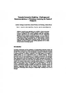
of the product model when the 3D image of the model is overlaid on it. Since the tangible object is designed with generic features, many different types of personal electronic product can be successfully simulated in the IMMS. 3. The overall architecture of immersive modeling system The IMMS consists of several hardware components and software modules as shown in Fig. 1. There are several important issues to be considered when it is developed. The hardware components are carefully selected based on their performance characteristics, ease of integration and flexibility for future enhancement. Each software module is also developed by using a modular design concept and taking performance optimization into consideration. In the design and development of hardware components and software modules that are integrated into a single platform, we aim to achieve truly immersive real-time interaction with a product model, that is natural, intuitive and easy-to-use. Software modules of multi-modal interface systems usually consist of many different toolkits and software libraries. The software modules of the IMMS are no exception in that respect. The IMMS has been developed using freeware including CHAI 3D [16], an open haptic tool kit, ARToolKit [17], a software library for building Augmented Reality (AR) applications, and Open source Graphics Language (OpenGL) application programming interface (API). We also use modules developed by ourselves for visual realism, auditory realism, force feedback and tactile realism, and functional realism. Each module has been developed under the Microsoft Visual Studio.NET 2003 environment. In this research, we aim to integrate three major sensory modalities seamlessly. The visual realism module provides the user with stereoscopic visualization of 3D CAD product models. It allows the user to manipulate, test and evaluate them. A stereoscopic display is then used to provide the user with a more realistic 3D visualization. We use an ARvision-3D HMD [18] (video see through) that gives ‘left’ and ‘right’ eye views, from which the user can see a stereoscopic image of the 3D model. The ARToolKit, a software library for building augmented reality applications, Open source Graphics Language (OpenGL) application programming interface (API) and OpenCV [19] are used for a stereoscopic display interface. The force and tactile module increases the realism by providing the users with a more natural and intuitive interface using the touch sense. Moreover, it adds more realism especially when it is synchronized with the visual and auditory senses. Any haptic device can be used to implement a haptic interface with the 3D model. The Omni model from SensAble Technologies Inc. is used since it is portable and can be easily integrated with other modules. In the IMMS, we use an open source haptic toolkit, the CHAI 3D SDK, to implement the haptic interface with the 3D model. Force and tactile realism for personal electronic products is presented to the user with kinesthetic feedback (force, motion) and tactile display (cutaneous touch). The kinesthetic feedback enables the
Portability Collaborative work
×
× ×
×
× × × × × ×
× × × × ×
user to have a perception of object shape, buttoning effects, and mechanical properties and the tactile display expresses vibration. The auditory realism module plays an important role in increasing the immersion by complementing the visual and tactile realism. The auditory sense can be processed in parallel with the visual and touch senses. In this study, the auditory sense for interacting with personal electronic products is represented by the control and spatial sounds. The control sound enhances the auditory realism by generating sounds when the user interacts with the 3D model when pressing a button on the model. The spatial sound adds more realism to the user by enhancing the user’s perception to the position of sound sources. The effect of interaction with the sound source is achieved by using audio processing techniques such as head-related transfer function (HRTF) [20], crosstalk cancelation [20], and room reverberation [21]. The functional realism module enables the user to test and evaluate all the functions of the product model. Functional realism is implemented by the human machine interaction (HMI) model [22–24] which can represent the functional behavior of a personal electronic product. The HMI functional model is an information model that represents the functional behavior of a product while the user interacts with it. The functional behavior is acquired by using a finite state machine that can represent the transitions between the states of the product. 4. Design of the multi-modal interface Conventional AR methods mainly focus on visual feedback. However, the addition of touch and auditory senses can give better immersion. In this study, we use multi-sensory feedback that includes visual, auditory and tactile senses to enhance immersion. The user wearing a 3D HMD on his head interacts with a virtual object by grasping and manipulating a tangible object. The tangible object is a mock-up model of a product with multiple fiducial markers attached on it to provide 3D information. A 3D model is overlaid on the whole area of the tangible object excluding the hand area, and vibro-tactile feedback and sound feedback are provided to the user based on various events occurring during operations. 4.1. Visual realism Visual realism allows the user to be immersed in the product model through the visual sense. Visual realism for personal electronic products is achieved by an immersive stereoscopic display of the model using an HMD. 4.1.1. Generation of a 3D geometric model A 3D geometric model of a product must be generated before adding more visual realism on the product model. We can generate the 3D geometric model of the product by sampling the surface
Please cite this article in press as: Lee Y-G, et al. Immersive modeling system (IMMS) for personal electronic products using a multi-modal interface. Computer-Aided Design (2009), doi:10.1016/j.cad.2009.11.003
ARTICLE IN PRESS 4
Y.-G. Lee et al. / Computer-Aided Design (
)
–
e a
b
c
d
Fig. 1. The overview of the immersive modeling system: (a) Visual realism, (b) Force tactile realism, (c) Auditory realism, (d) Functional realism, (e) IMMS.
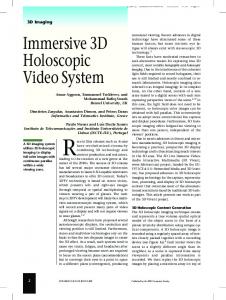
data of the mock up model. The recent technological advances in acquisition systems enable us to acquire both geometry and color of the given model as 3D clouds of points with high density and accuracy [25]. We acquire 3D geometry data from the real object using a commercial 3D scanner, the OptoScan from Breukmann [26]. A post processing step is then required to filter the noise from the clouds of points that represent different views of the object and to merge them. Once they have reached the required degree of quality, the surface reconstruction of the product model is performed. In our study, we reconstruct the model using meshbased representations since they are better suited for immersive modeling due to their simplicity and efficiency in rendering speed and quality. The QEM [27] (Quadric Error Metrics), a mesh simplification method, is used to maintain a high level of geometric detail while reducing the mesh size greatly. 4.1.2. 3D visualization using augmented reality In the conventional desktop-based product design environment, users view a virtual object through a monitor in a fixed position. In such a situation, the view space is in the monitor and the interaction space is constructed through the mouse or the keyboard on the table. This can cause an unnatural interaction because each space is not coordinated. But in an AR [15,28,29] based product design environment, viewpoints between the virtual object and user interaction are integrated, so that the user wearing an HMD can directly touch or observe the virtual model by using their hands. This allows more intuitive and immersive interactions. However, several problems exist in applying AR technology to the product design. First, an augmented virtual object usually has no physical entity so that we cannot touch it, which reduces immersion. In our proposed system, the user can interact with the virtual object which is overlaid on a tangible object. By registering the nonphysical virtual object with the physical tangible object on a corresponding scale, a significant immersion can be achieved. The virtual object now has a physical entity, thus reducing the gap between the virtual and the real environments. In our study, a tangible object is designed and interaction methodologies are developed. Basically, multiple markers are attached to the tangible object so that the virtual object can be augmented when one of the markers is detected. It is often unavoidable for the markers to be
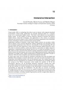
obstructed by the hands when the user grasps the tangible object. The tangible object is designed as shown in Fig. 2(a); it can simulate many different handheld personal electronic products that have a folder-type structure such as a game phone. Another annoying problem occurs when the virtual object occludes users’ hands. Such an occlusion effect by computer graphics objects causes visually awkward images and thereby reduces the level of immersion. Our method reduces the occlusion phenomenon by using hand segmentation. In addition, the segmentation method works well under changing lighting conditions. As a result, the proposed method provides better immersion to the user when he/she interacts with the virtual object. The proposed hand segmentation works as shown in Fig. 3. At first, we reduce the processing time by processing only the hand area on the tangible object instead of processing an entire image. To process locally, the 3D outer points of the tangible object are projected to a 2D image, and then the convex hull points are extracted [30]. Using these points, contours (upper surface, bottom surface) are extracted and skin-regions are segmented. Then, we apply the statistical approach to segment the hand from the area of the tangible object. The hue and saturation components of the HSV color space are used to minimize the lighting effects. Through ‘‘Kernel Density Estimation’’ using ‘‘Parzen Windows’’ [31], we can estimate an unobservable underlying probability density function based on the observed data. The first peak of the distributions can be easily found in the histogram, being the bin with the largest value. The second peak is then detected by multiplying the histogram values by the square of the distance from the first peak. This is the peak that is not close to the maximum. The valley between the distributions is obtained from the minimum histogram value between the two peaks [32]. From this data, threshold values are chosen and segmentation is executed. Finally, the extracted hand objects are overlaid again on the augmented virtual object. In order to achieve this, a processor is added to the graphic pipeline. If pixels in the silhouette image exist, corresponding input pixels are overlaid on the augmented virtual object again. As a result, users interacting with augmented virtual objects by hand will experience better immersion and more natural images. A survey of the usability test was done using visitors who participated in the next generation computer industry exhibition, KINTEX (Korea International Exhibition Center), Korea, on Nov, 2006.
Please cite this article in press as: Lee Y-G, et al. Immersive modeling system (IMMS) for personal electronic products using a multi-modal interface. Computer-Aided Design (2009), doi:10.1016/j.cad.2009.11.003
ARTICLE IN PRESS Y.-G. Lee et al. / Computer-Aided Design (
)
–
5
Fig. 2. (a) A folder-type tangible object. (b) Registration of a virtual object to the tangible object with corresponding scale.
Fig. 3. Proposed hand segmentation process.
The number of subjects was 45, and the gender ratio of male-tofemale was 40:60, respectively. The age ratio of 10/20/30/40 age groups was 12:76:4:8, respectively and most of the subjects were in their twenties. 38% of subjects had heard about the AR/MR research area or experienced relevant systems. Excepting one item about priority, each survey item was evaluated at 5 levels, 1 being the lowest value and 5 the highest value. (1: not very immersive/easy, 2: not immersive/easy, 3: normal, 4: immersive/easy, 5: very immersive/easy). The questionnaire was about the degree of immersion with respect to a reduction of the hand occlusion effect. The experienced subjects who had heard about new research into AR or had used it scored on average 4.29 points. The inexperienced subjects scored on average 3.83. Both the experienced and inexperienced subjects showed positive responses about the hands being shown for more immersion. According to experiments, the additional image processing for hand segmentation results in a bit slower rendering of AR contents. Note however that the advantages of the proposed method using hand segmentation outweigh the increased computational cost and resulting slower rendering. Also to explain the different responses of the experienced and inexperienced subjects, it appears that most experienced subjects were already interested in visual effects and fully understood the problem of the hand occlusion effect. 4.2. Force feedback and tactile realism Haptic sensation can be roughly classified into two modalities: kinesthetic feedback (force, motion) and tactile display (cutaneous
touch). The kinesthetic feedback encompasses the perception of large scale details as object shape and mechanical properties [33]. This is achieved by feedback from the muscular and skeletal system. The tactile perception is through the mechanoreceptive nerve ending in the skin. It is primarily a means of relaying information regarding small scale details that cause skin stretch, compression and vibration. With graphic visualization and auditory information, haptic interaction helps to have deeper recognition of the object, and enhances the sense of immersion. For immersive interaction with a personal electronic product model, we provide models of haptic material properties (stiffness and friction) to represent the surface feeling of the 3D model and the haptic widgets (button, slider and joypad) that are commonly used in general electrical appliances as shown in Fig. 4. The placement of haptic widgets is accomplished by low level programming and no interactive or scripting input is available. The stiffness is the resistance of an elastic body to deflection by an applied force. Once a haptic probe makes contact with the surface of a 3D model, a contact response force is calculated by the spring model with a stiffness using Hooke’s equation. The surface stiffness coefficient is assigned to each surface of the personal electronic product. The friction can be roughly divided into two categories: static and dynamic friction. The static friction, also called starting friction, is the friction between two objects that are in contact but are not moving. On the other hand, the dynamic friction is the resistance to relative movement of two bodies that are already in motion. When the user touches the body of the personal electronic product or moves while contacting the surface of the body, the user can feel the friction force. The friction is simulated by
Please cite this article in press as: Lee Y-G, et al. Immersive modeling system (IMMS) for personal electronic products using a multi-modal interface. Computer-Aided Design (2009), doi:10.1016/j.cad.2009.11.003
ARTICLE IN PRESS 6
Y.-G. Lee et al. / Computer-Aided Design (
Fig. 4. The haptic widgets in a personal electronic product.
adding a lateral force to the movement of the haptic probe. Fig. 5(a) shows a force profile of friction with respect to the user’s contact movement. Effective forces in CHAI3D represent haptic surface properties such as stiffness, static friction, and dynamic friction. These coefficients are modeled for each part of the personal electronic model and applied to the user when the contact response force is computed. In order to model the mechanical functions of the haptic widgets, we use dynamic property models that can effectively display the dynamic motion and force characteristics of each haptic widget. The dynamic property models are implemented as a haptic module in CHAI3D by creating dynamic mesh structures and surface property structures. The dynamic mesh structure represents the characteristics of mechanical dynamic motion of the 3D haptic widgets. It simulates the motion of push buttons, a slider, and a joypad haptically as well as graphically. The haptic module simulates various push button effects on the personal electronic product. In this study, we use a basic push button whose force profile consists of three stages as shown in Fig. 5(b): an initial springy region where the force increases linearly with displacement; a mid region of a sudden decrease in resistive force and transition to a dead band where the resistive force is constant; a final hard stop region where the force approximates the hard surface. When no force is applied, the button returns to its initial position. The parameters of the spring coefficients, the button’s traveling distances, and the dead band force can determine the dynamic properties of a specific mechanical button. A slider is usually used for selecting one of the functions in an electronic product. The slider has a number of notches that represents the slider’s fixed position along its travel axes as shown in Fig. 6(a). It can therefore be modeled with the force profile according to the notch region and position. Fig. 6(a) shows the force magnitude versus a slider position with notches in the travel axis. Each notch is evenly spaced along the entire travel of the slider.
)
–
The force increases linearly in the center of the notch region and then it decreases linearly to the next notch shown in Fig. 6(a). As a result, the user can locate the slider notch by notch and feel the interaction force of the slider. When no force is applied, the slider returns to the center notch. We have also developed a haptic joypad model that is usually used to scroll and navigate user interface menus. The joypad can be modeled based on the haptic button force model in the moving direction. The joypad movement represented in Fig. 6(b) corresponds to upward, downward, left, and right directions. Typically, the joypad rotates about two axes in response to the applied force location. When the joypad is touched, collision detection and contact force calculation are first performed in CHAI3D, and then the magnitude of the force along the two axes is compared. If the force along the first axis is greater than the second one, the second axis is selected and vice versa. When the applied force is greater than the prescribed threshold by the spring coefficient, the joypad starts to rotate at the pre-specified rotating rate. After rotating by a certain angle, an event is triggered for working specific functions in the 3D model. When the joypad is not being touched it returns to the home position with a different spring coefficient. In addition, we have utilized a bump-mapping technique to give the tactile feedback that mimics the surface roughness when a user scratches the specific surface of a virtual object with the haptic device. The bump-map surface, which is an array of height values for generating the surface textures, is made from two dimensional texture images used in visual rendering. The bump-mapping technique, in combination with haptic material properties (stiffness, frictions) closely simulates the haptic sensation of a surface with certain materials and roughness. To achieve more immersion, additional vibrotactile haptic sensation is embedded in the tangible object. The inside of the tangible object is mainly composed of five parts as shown in Fig. 7: vibration motors, a micro-controller, a Bluetooth module, a battery, and a shooting button. When the server sends the intensity of vibration, the Bluetooth module receives the data and the micro-controller activates the vibration motors. When the user pushes the shooting button, the micro-controller sends a shooting signal to the server through Bluetooth. Tactile realism is significantly influenced by human feeling. However, it is difficult to intuitively find out the optimal haptic parameters that induce the realistic tactile feeling for certain objects. For this, we conducted the experimental tuning of the haptic parameters in advance for every part of the personal electronic product model to enhance the quality of tactile realism. 4.3. Auditory realism A profound immersion can be delivered to the user when auditory realism is added. Such auditory realism can be presented to the user with different sounds. One of them is the control sound that is played when the user manipulates a personal electronic
Fig. 5. (a) Force profile of friction, (b) Force profile of a haptic button. Please cite this article in press as: Lee Y-G, et al. Immersive modeling system (IMMS) for personal electronic products using a multi-modal interface. Computer-Aided Design (2009), doi:10.1016/j.cad.2009.11.003
ARTICLE IN PRESS Y.-G. Lee et al. / Computer-Aided Design (
)
–
7
Fig. 6. (a) Force profile of a slider with three notches, (b) Force profile of the Joypad.
Shooting Button 3.7V Li-ion Battery Vibration Motor Microcontroller
Bluetooth Module
Fig. 7. The tactile display embedded in the tangible object.
product [34]. The control sound can enhance realism by adding the appropriate sound effect while manipulating the product model. For example, when the user pushes a button strongly the control sound is played more loudly and vice versa. We provide different sounds to the user depending on the user’s action on the immersive model [35–37]. Another type of sound interaction is multidimensional or spatial sound which allows the user to perceive the position of sound sources and the effect of the sound sources in the immersive environment [38]. This sound interaction is realized with the assistance of spatial audio recording, sound processing, and sound reproduction techniques. We describe the two major sound effects below. 4.3.1. Auditory realism using control sounds Since the types of interaction with the product model are huge, the number of control sounds required is also numerous. It is timeconsuming to generate and store a huge number of control sound files. An efficient method is proposed to overcome this problem. The method consists of two steps: a preprocessing step and a sound generation step. In the preprocessing step, different types of sound of interaction with the product model are prepared by considering possible circumstances and classifying them into different event types, such as pushing the power-on button, dropping the model on the floor, and opening the battery cradle. Each event type has several different attributes and a default value is assigned to each attribute. Then a sound appropriate to each event type with a different attribute is collected. In the sound generation step, an event is classified and assigned a proper attribute value of the corresponding event type. Finally, the sound file with default attributes is transformed to the proper sound and is played out on the speaker system. Table 2 shows the list of attributes used for generating control sounds in this study. Different types of control sound can be generated using these attributes. Detailed novelty of the used method is given elsewhere [39]. Fig. 8 shows the procedure of generating the control sound by adjusting the attributes, in this case, intensity and contact area. The intensity attribute represents the pressure force level that the user exercises on the product model. The control sound is played
louder as the value of the intensity attribute increases. The contact area indicates the friction area that the user makes contact with the product model. The change in the size of the contact area influences the spectrum of the control sound. Our method processes the control sound by transforming the spectrum of the sound in the case of changing the contact area. A simulator that can generate different control sounds in real-time is developed when changing the button type and the attribute values. The above control sound generating process is similar to a sonification approach for making MIDI audio signals. However, the control sound generating method described above cannot be implemented using existing sound file formats since the existing sound files do not have any information on the situation where the sound is recorded. Therefore, the sound system cannot determine whether the sounds are suitable to the user’s action with the digital mock up product model on the IMMS. To solve this problem, we used a new sound file format that contains some information on the characteristic of the sound, and defines some sound factors for the machine control sound to simplify the information about the situation. 4.3.2. Auditory realism using spatial sound In the IMMS, the auditory realism is enhanced using the spatial sound (3D) effect [36]. We develop a binaural rendering technique based on the head-related transfer function (HRTF) [20] to obtain a 3D sound from monaural or stereo sounds. A crosstalk canceler is applied to the generated 3D sound to improve the 3D effect on a stereophonic loudspeaker system, where the filters used for the crosstalk cancelation are generated by using the HRTF. In addition, a reverberation effect is added to the generated 3D sounds considering the configuration of the room environment. Fig. 9 shows the overall structure of the 3D sound reproduction system in the IMMS. A sound source, typically the output of an MP3 player, is given as input to the 3D sound generator and is rendered into a 3D sound. To reflect the listener’s preference about the 3D effect, three parameters can be chosen: azimuth, distance, and elevation. If the listener wears a headphone, then the 3D sound goes directly to the reverberator. Otherwise, the crosstalk canceler followed by the reverberator is applied to the 3D sound to play it out on a loudspeaker system. In the IMMS, a reverberation simulator is developed, where an environment model can be chosen from predefined types including a room, studio, stage, club, and hall or it can be defined by the user. 4.3.3. Real-time implementation of the auditory realism for the IMMS We aim to implement the 3D sound processing in real-time. For example, the number of taps for the finite impulse response (FIR) implementation of the reverberation filters should be around 48,000 to handle one second delay of the reflected sounds in the reverberation environment. This implies that we have to perform 2.3 giga multiplications and additions per second when the sound signals are sampled at a rate of 48 kHz. Such a huge number
Please cite this article in press as: Lee Y-G, et al. Immersive modeling system (IMMS) for personal electronic products using a multi-modal interface. Computer-Aided Design (2009), doi:10.1016/j.cad.2009.11.003
ARTICLE IN PRESS 8
Y.-G. Lee et al. / Computer-Aided Design (
)
–
Table 2 The list of attributes used for generating control sounds. Attribute
Description
Sound characteristics (example)
Material Surface Hardness
Type of material used for the model Condition of the model surface Solidness of the model surface
Mass Contact area
Weight of the model Size of the frictional area between the model and the user (e.g., finger) Strength of operating the model Location where the model is contacted by the user
Sound quality (metal, plastic, rubber, wood, glass, and so on) Noisy or clear sound (rough or fair) Frequency component of the sound such as high-frequency or low-frequency sound (soft or hard) Intensity of the sound (light or heavy) Length of the sound (wide or narrow)
Intensity Direction
Loudness of the sound (weak or strong) Location of the sound in an acoustic space (angle; −180◦ to +180◦ )
Fig. 8. Procedure of generating control sounds by changing attributes.
Fig. 9. The sound reproduction system in the IMMS.
of multiplications cannot be done even with a high-speed PC. We could achieve a real-time implementation by applying a fast Fourier transform to the sound signals and using an overlap-andadd method for filtering.
auditory realism. However, if the user touches the object in different ways with respect to the simulated scenarios, there may exist a dissociation between the tactile and auditory realism. 4.4. Functional realism
4.3.4. Connection of tactile and sound realism In real life, human behaviors inducing tactile feeling often accompany corresponding sounds when a human touches the surface of an object with his/her hand. This tactile feeling and the corresponding sounds are closely related to each other because both are the consequence of human hand manipulations for the object. However, because the human behavior to touch the object is complex, associating the tactile feelings with corresponding sounds seamlessly for various hand interactions remains one of the difficult tasks. For this reason, in the presented work, we limited the tactile and auditory realism modules to be individually operated, without having a close relationship. For example, when a user scratches the specific surface of a virtual object with a haptic device, the corresponding 3D sound is triggered to enhance the
Every personal electronic product has an embedded computer chip that contains all needed functions of the product, many of which are human–machine interaction (HMI) tasks. Some software tools such as TM Rapid Plus and TM PlayMo 3D are available for modeling and simulation of product’s functional behavior, but they do not provide an open architecture that allows the functionality to be easily integrated into immersive environments, and it is not easy to represent the functional behavior of complex products in detail using the tools. In order to realize the immersive experience of a personal electronic product, it is very important for the user to understand the functional behavior of the product with ease and clarity. Fig. 10 shows the overall process of the HMI function simulation module
Please cite this article in press as: Lee Y-G, et al. Immersive modeling system (IMMS) for personal electronic products using a multi-modal interface. Computer-Aided Design (2009), doi:10.1016/j.cad.2009.11.003
ARTICLE IN PRESS Y.-G. Lee et al. / Computer-Aided Design (
)
–
9
Fig. 11. Control flow of the finite state machine.
Fig. 10. The overall process of HMI functional simulation.
that is used in this study. We capture the functional behavior of the product into an information model and utilize it using a finite state machine to simulate the functional behavior in an immersive environment. 4.4.1. Generation of HMI functional model The HMI functional model of a product is an information model that represents the HMI-related functional behavior of the product. In this study, we adopt a state transition methodology [22–24] to capture the functional behavior of a personal electronic product by breaking it down to the following entities: – – – – –
All HMI events to occur in the product All states in which the product can be Activity information related to each state State transitions occurring in each state Event-condition-action information related to each state transition.
Every personal electronic product has some components such as lamps, switches, buttons, sliders, indicators, displays, timers, and speakers that are used during interaction between the user and the product. They are called the objects making the basic building blocks of functional simulation. Every object has a pre-defined set of properties and functions for a real-time situation. The overall behavior of the product is broken down into separate units of behavior, which are called states. A state can be as brief as a fraction of a second, or extend for several seconds, minutes, or hours. Each state, no matter how brief, is a distinct unit within the system’s life cycle. The state of the product can be changed to another state. This is called the state transition. Every state transition is triggered by one or more events associated with it. A transition occurs when events are activated and some specified conditions are met. Some tasks called actions can be performed before the transition to a new state. In order to define the actual behavior of the product, all the tasks performed in each state are specified. These tasks are called activities. They only occur when their state becomes active. Actions and activities are constructed using the objects’ properties and functions. Each action or activity consists of a set of statements. Each statement can be either the assignment of some value to a variable or the calling of a function of an object. In this study, we have devised a simple markup language to represent the functional behavior of a product. After analyzing and gathering the above-mentioned entities of the functional behavior, we write them into a set of text files based on the markup language
to build the HMI functional model. In the HMI functional model, each action or activity consists of a set of logical statements expressed with the objects’ properties and functions. The concrete execution according to each action or activity is conducted during the functional simulation. 4.4.2. Construction of a finite state machine The finite state machine (FSM) is used as an engine to control the transition between the states of a product based on the HMI functional model. In this study, we have developed a module to compile the text files for the HMI functional model and to operate the FSM. Fig. 11 shows the control flow of the FSM module. Note that the actions or activities, logically defined in the HMI functional model, are invoked during the functional simulation. Some function libraries for processing audio/image/video data are often required to perform functions related to image synthesis and display, playing audio sounds, and handling video animation data. 4.4.3. Acquisition of multimedia contents data Multimedia contents data are used to create visual and auditory display information required for vivid simulation of the functional tasks. We use three kinds of multimedia content data in this study: graphical images, audio sounds, and video animations. Every personal electronic product has at least one LCD display to show visual information related to its specific states. Such visual information includes graphical images and video animations. Also, the product has audio sounds specific to its states. We use the JPEG file format for graphical images, MP3 or WAV file formats for audio sounds, and the AVI file format for video animations. The multimedia contents data, which can be purchased or acquired by audio/video recording, are managed by a database management tool for their adequate use in the immersive virtual environment. 4.4.4. Simulation of functional behavior The functional behavior simulation of a product is completed as shown in Fig. 10. When the user creates an input event, the HMI functional simulator checks if the event is related to the functional behavior of the product or not. If so, the FSM module refers to the HMI functional model of the product and determines if the event triggers a state transition. If the state transition is confirmed, the FSM module does the specified actions and changes the state to a new one, and performs the activities of the new state. The execution of the actions and activities yields state-specific visual and auditory data. The state-specific visual data are sent to the functional simulator to update the visual image of the product, and the state-specific auditory data are sent directly to auditory output devices.
Please cite this article in press as: Lee Y-G, et al. Immersive modeling system (IMMS) for personal electronic products using a multi-modal interface. Computer-Aided Design (2009), doi:10.1016/j.cad.2009.11.003
ARTICLE IN PRESS 10
Y.-G. Lee et al. / Computer-Aided Design (
Fig. 12. The IMMS hardware configuration.
5. System integration The IMMS platform consists of many hardware components and software modules. The hardware components of our IMMS platform are shown in Fig. 12. The PC-based IMMS platform uses AMD Opteron Dual Core175 (2.2 GHz) CPU and 4 GB PC2-3200 ECC DDR2 SDRAM for high speed computing. To accelerate the graphics rendering speed, we use Quadro FX4500 manufactured by nVIDIA. To give a stereoscopic display of 3D models, ARvision-3D [18] video see through head-mounted display is used. A PHANTOM Omni [37] haptic device from SensAble Technologies Inc. is used to provide force and tactile realism. A tangible object is also designed with an embedded Bluetooth module and two vibration motors. A universal computer-supported speaker Britz BR-5100D is used to implement auditory realism. 5.1. The operation of main modules The diagram in Fig. 13 shows the main modules of the Immersive Modeling System. The core management module plays the central role and manages the four realism modules. To monitor events or messages generated by the modules, the core management module runs at 30 Hz. First, it calculates the transformation matrix of a tangible object and a 3D product model, and applies it to accommodate the motions of the 3D model. Second, it checks dynamic object ID when a user interacts with buttons of the 3D model, and sends the pressed button ID to the functional realism module to activate specific functional simulation. Finally, it executes the corresponding 3D sound converted by the auditory realism module according to the state of the FSM. The visual realism module utilizes the augmented reality technique to present the stereoscopic view of a product model to the user. After a 3D model is loaded, it is continuously rendered by a graphic thread which operates at 30 Hz. To manipulate the 3D model by using a tangible object, the module performs a calibration to coordinate the operations of haptic and graphic modules and tries to reduce noise to prevent the tangible object from trembling. The visual realism module uses the transformation matrix calculated by the core management module to overlay the 3D model on the tangible object that is being moved. The loaded 3D model consists of two types of object: dynamic objects and static objects. The static objects denote non-movable parts such as the main body, LCD panels and speakers. The dynamic objects denote moving parts and are composed of buttons, sliders and a joypad. To achieve realistic tactile realism, haptic material properties of each object need to be well tuned in advance. When a user interacts with the dynamic objects, the selected object can be moved or rotated in proper directions following the movement direction of the haptic device. The user can simultaneously see the movement of the object while sensing the force feedback from it.
)
–
The auditory realism module presents stereoscopic sound to the user. When the functional realism module produces a 3D sound generation message, the core management module delivers the corresponding sound ID and commands the auditory realism module to generate corresponding 3D sound according to the FSM state. The sound source is given as input to the 3D sound generator and it is rendered into a 3D sound. The functional realism module simulates the functionality of the personal electronic product. When the user presses the button on the 3D model, the HMI functional simulator checks if the event is related to the functional behavior of the product. If so, the FSM module refers to the HMI functional model of the product and determines whether the event triggers a state transition. If the state transition is confirmed, the FSM module performs the specified actions. During execution of the specific actions, the corresponding visual data are sent to the visual output device and the corresponding auditory data are also sent to the auditory output devices. 5.2. Integration issues Each realism module has been developed and tested independently. When these modules were integrated using a seamless multi-modal interface to give high level of immersion, however, there are many important integration issues to resolve. The major issues of a multi-modal interface system can be categorized as follows: – – – – –
Real-time implementation Optimal resource management Unification Stability Connection of hardware and software.
For the real-time implementation, we describe a real-time interaction problem with a 3D model. For the optimal resource management, we present a multi-thread system that can optimize the use of computing resources. Many different modules need to be unified in a multi-modal interface system, but the registration of coordinate systems is a critical one, so we discuss it along with the unification problem. The stability is also very important not to decrease the level of immersion. We describe a reduction of visual noise, correction of collision detection, and marker tracking problems that we have experienced while enhancing the stability of the system. There are also connection problems of hardware as well as software, which have been encountered frequently during the development. However, the details are not presented in order to highlight the first four major difficulties in this paper. 5.2.1. Real-time interaction with a 3D model Real-time interaction is necessary to achieve a natural, intuitive and comfortable interaction with a 3D model. But, it is very difficult to render the 3D model or interact with it using a haptic device in real-time due to the size of the data sets. Therefore, the size of the data sets needs to be reduced for the real-time interaction. In the IMMS, QEM [27] technique is used to reduce the size by simplifying the model. In representing the 3D model, a polygonal mesh is used, since it gives the most appropriate geometry representation for interactive 3D graphics applications due to its simplicity, flexibility and efficiency. In addition, the OpenMesh [40] data structure is employed due to its flexibility and memory efficiency. To represent texture, a single texture image is mapped onto the 3D geometric model. If we use the vertex color instead of a texture image for appearance, the file size of 3D model increases considerably. This causes a great overload in data handling and rendering. When integrating the haptic interface into the IMMS platform, the most important issue is to render the 3D model in real-time
Please cite this article in press as: Lee Y-G, et al. Immersive modeling system (IMMS) for personal electronic products using a multi-modal interface. Computer-Aided Design (2009), doi:10.1016/j.cad.2009.11.003
ARTICLE IN PRESS Y.-G. Lee et al. / Computer-Aided Design (
)
–
11
Fig. 13. Architecture of the IMMS platform.
for visualization as well as haptic interaction. It is generally accepted that the update of visual rendering of the model must be done with a frequency of at least 30 Hz to avoid flickering. However, the haptic rendering must be updated at 1000 Hz in order to have realistic force feedback and vibro-tactile display. So the haptic rendering algorithm should be implemented as efficiently as possible since the haptic rendering takes much more hardware resources. In the IMMS platform, the CHAI 3D SDK [16], an open source haptic toolkit, is used to implement the haptic interface. 5.2.2. The integration of hardware and software components IMMS is composed of various hardware such as a haptic device, a tangible object and a camera module. The system also uses open software libraries which are CHAI 3D and ARToolKit for the haptic device and the camera module, respectively. These two libraries have to be embedded in the multi-threaded application to avoid hardware and software conflicts caused by different frame rates. As mentioned before, at least a 30 Hz frame rate is required for graphic rendering while a 1 kHz frame rate is needed for haptic rendering. The software modules of the IMMS platform are designed to be operated using multiple threads by having dedicated threads for each module. The IMMS also provides a cross-platform thread class to allow developers to further divide computations into more threads. By dedicating separate threads with different capacities for different realism modules, the IMMS can be executed without overspending computing resources on a specific module. A Bluetooth software module for the tangible object is independently executed to avoid conflicts with other components. Consequently, the data is exchanged using the shared memory for communication between the Bluetooth software module and the tangible object. This method can avoid a conflict problem efficiently because the software module is not embedded in IMMS. IMMS also uses the shared memory when it communicates with other software module such as a game module. For example, if a car collides with other object, the vibration mode is triggered and this data is transmitted to IMMS using the shared memory. Then IMMS sends a signal to the Bluetooth software module to vibrate the tangible object. Contrarily, if the user presses a button on the tangible object, this data is transmitted from the Bluetooth module to IMMS and the data is again delivered to the game module and then a gun associated with the button is fired in the game. The software integration using the shared memory is easy to implement, which can efficiently remove the conflicts among various components.
5.2.3. Registration of different coordinate systems Accurate registration and positioning of a 3D model require accurate tracking and sensing the location of a tangible object in the immersive environment. The IMMS uses several different coordinate systems: the OpenGL coordinate system for handling graphics, the camera coordinate system for realizing augmented reality and the coordinate system for haptic devices. The use of multiple coordinate systems causes many unexpected results. For example, if the 3D model is not displayed where the real tangible object is, the user will miss the tangible object. Due to a mismatch of the coordinate systems, the user cannot touch the 3D model, which will lead to a wrong interaction. To resolve this kind of problem, we calibrate each coordinate system with respect to a single world coordinate system. Each coordinate system is suitably transformed using the same projection matrix. However, there still exists a mismatch between the camera and the OpenGL/haptic coordinate systems due to the different view points between the camera and the OpenGL/haptic coordinate systems, as shown in Fig. 14. We resolve the mismatch of these coordinate systems by rotating the y-axis of the camera coordinate system using the homogeneous coordinate transformation. 5.2.4. Reduction of visual noise Noises such as flickering or shaking in the stereoscopic images during tracking a 3D model seriously hamper immersion for the multi-modal interface. Even when a tangible object is stationary, noticeable flickering or shaking occurs on the 3D model overlaid on it. This results in unsatisfactory visual quality and makes the user very uncomfortable during the interaction with the 3D model. This flickering or shaking problem is not easy to measure and eliminate, since it is often non-systematic and difficult to characterize. In order to alleviate this problem, we apply low pass filtering techniques that reduce noise that is generated from the tracking and sensing system. The low pass filter eliminates the high frequency noise beyond the filtering threshold of 50 Hz, since it successively calculates the errors between the values in advance. 5.2.5. Correction of collision detection During haptic interaction with a 3D model, users may feel force discontinuities and abrupt force feedback. These phenomena originate from the triangle mesh artifacts e.g., holes, cracks, overlap, inconsistent normal orientation, and gaps between separate
Please cite this article in press as: Lee Y-G, et al. Immersive modeling system (IMMS) for personal electronic products using a multi-modal interface. Computer-Aided Design (2009), doi:10.1016/j.cad.2009.11.003
ARTICLE IN PRESS 12
Y.-G. Lee et al. / Computer-Aided Design (
)
–
Fig. 14. Camera calibration for visual and AR and haptic view.
geometric models. When a user explores with the 3D model haptically, the user interacts with the object through the tip of the haptic probe i.e. HIP (Haptic Interaction Point). At the same time, we may also consider another point called a proxy (also called the godobject, or the ideal haptic interaction point (IHIP)). While the haptic probe can penetrate into the 3D model, the proxy stays on the surface of the virtual object. The reaction force is then computed by a penetration vector that is multiplied by the prescribed virtual stiffness. Since collision between the haptic probe and the 3D model conventionally detects the point of the physical haptic interface on the position in the triangular mesh of the 3D model, the collision may fail due to the above triangle mesh artifacts. For eliminating these artifacts, Ruspini et al. [41] proposed the virtual proxy as a massless sphere that moves among the objects. The radius of the proxy is large enough to avoid falling through the holes in the underlying 3D model. In addition, they compute a possible path of the proxy when the proxy collides with the 3D model and then creates the volume that covers the geometry of the 3D model. This approach may able to prevent falling of the proxy when the 3D model is not divided into different parts. However, the personal electronic model is composed of different models such as body, buttons, slider, etc. Thus, an abrupt or unwanted force can be generated in the haptic rendering computation. To overcome these drawbacks, we first improved the quality of the 3D model by eliminating the holes and cracks in the CAD modeling process by using 3DMax or Maya. However, there is still abrupt force feedback due to the gaps between separate geometric models. Fig. 14(a) shows two buttons side by side in the 3D model, and represents that the proxy is located on the top of the gap between the two button models. When the proxy is located there, the proxy may fall into the gap because an inconsistent mesh exists. In addition, it is very difficult for the user to escape from the gap and hole between the buttons or the buttons and the body at current time (t) as shown in Fig. 15(b), which represents another view point of Fig. 15(a). To overcome this problem, we monitor the surface normal and the penetration vector between the proxy and the haptic probe as shown in Fig. 15(c) and (d). If each normal of the surface and the penetration vector is in the same direction, the collision detection becomes false and thus the reaction force becomes zero (see Fig. 15(d)) and vice versa. On the other hand, the normals of the surface and the penetration vector are in the opposite direction, a reaction force is generated as well as the collision being detected. Using this scheme, the haptic probe can smoothly escape the hole or gap between two objects in the personal electronic product model. 5.2.6. Enhancement of marker tracking The IMMS system uses a marker-based tracking system which uses an optical tracking technique. When using a 3D video seethrough HMD [18], output images are captured at 30 fps and
their resolution is 640 ∗ 480 pixels. However, detection of the markers on the tangible object often fails when the light condition changes. This problem is caused by the shades generated from the hands or spot light sources. To reduce these noises, ‘local adaptive threshold’ [42] is used to obtain the binary image from the output image. Then, the threshold value of each pixel of the binary images is assigned by the mean value of each block unit. The size of the block is adaptively chosen with respect to the size of the marker. By applying these steps, the marker is detected robustly regardless of lighting conditions. 5.3. Application examples to personal electronic products In the IMMS, the user can manipulate a personal electronic product and test every function using the multi-modal interface. In order to test the given functions of a product, its 3D model has to be created and all states, state-transitions and activities have to be provided as input to the HMI functional realism module. Fig. 16 shows various states of different product models. For example, Fig. 16(a) shows four major menus of an MP3 player. The HMI functional model is used to create a state transition chart, which represents all the states and possible state transitions between them. Fig. 17 shows a state transition chart for the MP3 player where we consider only two main functional features: playing MP3 music and listening to an FM radio. The user can select any of them by pressing a button using a haptic interface, and Fig. 16(b) shows the LCD window while playing MP3 music. To further demonstrate the applicability of the IMMS to personal electronic products, we also created 3D models of a game phone and a portable media player (PMP), and also prepared all the functions related to these products. These three personal electronic products can be fully operated using 3D models and the IMMS platform without making real physical models. Fig. 16(c) and (d) show two games that can be played using the IMMS. The games are played by pressing buttons and also tilting the tangible object. The user can feel that he/she is operating a real game phone while he/she is playing these games in the IMMS. For example, the user can play a racing game displayed on an augmented virtual object by tilting its tangible object in all directions. These directions control the speed and direction of a car in the game. If the car collides with the wall or other cars, then 3D sound effects (e.g. an explosion) are played. The background sound is played by default. To provide more realism, if a collision occurs during the game, it makes the tangible object vibrate. Fig. 18 shows the racing game in action. The games can also be played on a different electronic product, PMP. Fig. 16(e) and (f) show most popular functions implemented in PMP. The advantage of the IMMS using the tangible object is that we can simulate many different types of personal electronic product
Please cite this article in press as: Lee Y-G, et al. Immersive modeling system (IMMS) for personal electronic products using a multi-modal interface. Computer-Aided Design (2009), doi:10.1016/j.cad.2009.11.003
ARTICLE IN PRESS Y.-G. Lee et al. / Computer-Aided Design (
)
–
13
Fig. 15. Escaping from the hole and gap in a product model.
a
b
c
d
e
f
Fig. 16. Application to MP3 player, game phone and PMP.
Fig. 17. State transition chart of the MP3 player.
using one tangible object as was demonstrated in this paper. The MP3 player, the game phone, and the PMP are quite different in terms of their design such as the configuration of the keypads and the shape of the LCD windows, and the mechanical design of
components, but they can be simulated using one tangible object. Since the tangible object is designed with generic features, it can accommodate a wide range of new personal electronic products. If the configuration of a new product is significantly different
Please cite this article in press as: Lee Y-G, et al. Immersive modeling system (IMMS) for personal electronic products using a multi-modal interface. Computer-Aided Design (2009), doi:10.1016/j.cad.2009.11.003
ARTICLE IN PRESS 14
Y.-G. Lee et al. / Computer-Aided Design (
)
–
Fig. 18. Playing games using a tangible object in the IMMS.
Table 3 Result of user evaluation tests. Experiment test
Mean value result, 1 (bad)–5 (good)
System integration
1. 3D interface for the visual, auditory, and force/tactile realism? 2. Immersiveness? 3. Overall system integration
3.9 3.8 3.9
Visual realism
4. Visual comfort without flickering? 5. Modeling of a PMP, a game-phone and an MP3? 6. Immersiveness when you play games in an AR environment? 7. Overall visual realism
3.6 4.0 3.7 3.8
Force/tactile realism
Auditory realism Overall
8. Haptical comfort without flickering? 9. Immersiveness of the pressing and sliding effect? 10. Immersiveness of the tactile effect? 11. Overall force/tactile realism
3.6 3.9 4.0 3.8
12. Control sound when you press a button? 13. 3D sound effect? 14. Reverberation effect? 15. Overall auditory realism 16. Overall system
3.6 3.7 3.6 3.6 3.7
then we must design a new tangible object, but most products will be handled by a few different types of tangible object. The use of tangible objects in the IMMS significantly increases the usability of a multi-modal interface system. It will greatly help the users to evaluate different product models without purchasing real products. 6. User evaluation To make a practical application for the IMMS system in design of personal electronic products, a user evaluation test was undertaken with 20 participants. All of the participants were volunteers; one was a university staff member, two were from an engineering institute, two were from a company, and the others were engineering students. Twelve participants had experience in an immersive environment. Two were aged 40–43, seven were aged 30–39, and the others were aged 20–29. The user evaluation test gave user feedback based on the questionnaire of the 16 features as shown in the second column in Table 3. It took approximately 5–10 min to make an experiment for the personal electronic products in the immersive environment. The user evaluation test was immediately followed by a questionnaire and interview session. The questionnaire listed 16 features of the IMMS system and the participants were asked to rate their opinions of each listed feature as ‘very positive’ (5), ‘positive’ (4), ‘neutral’ (3), ‘negative’ (2), and ‘very negative’ (1). The mean values of the questionnaire results obtained for each feature are given in the last column of Table 3. The result varies from 3.6 to 4.0. Among 16 features, the ‘Haptical comport without flickering (8)’ and ‘Reverberation effect (14)’
have the lowest scores as 3.6 while the ‘Modeling of PMP, gamephone and MP3 (5)’ and ‘Immersiveness of the tactile effect (10)’ have the highest scores as 4.0. The final ‘overall system (16)’ in the table gives the mean value as 3.78 obtained for each feature. The results from the user evaluation test demonstrate the usability and efficiency of our proposed IMMS system in the immersive modeling process. Although our proposed system cannot satisfy every requirement of practical applications in CAD field, we believe that it has particular strengths to designers in the early design stage of modeling for the personal electronic products. For instance, designers can save cost and time since they can estimate the preference of users by evaluating and testing the personal electronic products in the early design stage. The final ‘overall system (16)’ in the table gives the mean value as 3.78 obtained from each feature. Based on the results of the user evaluation test, we can know that the IMMS system can give better support capabilities for the immersive modeling through its multimodal interface integration and performance in the immersive environment. 7. Conclusion In this study, a novel multi-modal interface called the IMMS has been developed. The system consists of five main modules: visual realism, auditory realism, force/tactile realism, functional realism and the core management modules. In the system, visual, auditory and tactile/force feedback interfaces are handled by different realism modules while the overall scheduling of activities is taken care of by the core management module. In the IMMS, the interfaces using different senses are combined into a single platform.
Please cite this article in press as: Lee Y-G, et al. Immersive modeling system (IMMS) for personal electronic products using a multi-modal interface. Computer-Aided Design (2009), doi:10.1016/j.cad.2009.11.003
ARTICLE IN PRESS Y.-G. Lee et al. / Computer-Aided Design (
The system is also portable in that it can be built with a minimal set of hardware and can be used in the product development process as well as in the evaluation process of personal electronic products. It provides natural, intuitive and comfortable interactions for the user with a 3D product model in an immersive environment. As demonstrated by the example applications of the MP3 player, the game phone and the PMP, the user can test and evaluate the functions that each product offers using the multi-modal interface. The tangible object used in the study is generic in nature so that it can provide excellent immersion for simulating different electronic products. During integration, many integration issues that have been encountered could be resolved to some extent. In order to visualize a 3D model with photorealistic quality, the reflectance property of materials called BRDF [43,44] (Bidirectional Reflectance Distribution Function) needs to be measured and used for rendering the model. This photorealistic data, however, could not be integrated into the IMMS because of its large file size, which could compromise the performance of the system. Further research effort is required to build a multi-modal interface system that runs in real-time with a 3D product model having a photorealistic quality. Moreover, the IMMS has not been implemented for a distant user. Further work in networking and data compression and decompression is needed to realize this remote operation. There is also a limitation in the particular modality in terms of immersiveness and fidelity. Unlike the auditory modality which requires no device to put on and the sound is very close to the true sound, the haptic modality is limited in that one has to use a stylus to touch and feel something. In other words, the haptic cue is always indirectly felt by the stylus or gimbal and the point of contact is not collocated with the operator’s hands and fingers. An interesting extension to our system would be an ability to sense the weight of the personal electronic products and this would require a specialized force actuator and accompanying mechanisms on the mockup being held. The visual cues are quite realistic but the lack of photorealistic rendering and the wide field of view prevents the system from achieving enhanced realism. Acknowledgements This work was supported by Korea Science and Engineering Foundation (KOSEF) through the National Research Laboratory (NRL) Program funded by the Ministry of Education, Science and Technology, Korea (Grant No. 20090083091). References [1] Gupta Rakesh, Whitney Daniel, Zeltzer David. Prototyping and design for assembly analysis using multimodal virtual environments. Computer Aided Design 1997;29(8):585–97. [2] Choi SH, Chan AMM. A virtual prototyping system for rapid product development. Computer Aided Design 2004;36:401–12. [3] Robinson G, Ritchie JM, Day PN, Dewar RG. System design and user evaluation of Co-Star: An immersive stereoscopic system for cable harness design. Computer Aided Design 2007;39(4):439–45. [4] Ye J, Campbell RI, Page T, Badni KS. An investigation into the implementation of virtual reality technologies in support of conceptual design. Design Studies 2006;27(1):77–97. [5] Bao JS, Ritchie JM, Gu MQ, Yan JQ, Ma DZ. Immersive virtual product development. Journal of Materials Processing Technology 2002;129(1–3): 592–6. [6] Zhang Ying, Travis Adrian R.L., Collings Neil. Evaluation of multi-sensory feedback on the usability of a virtual assembly environment. Journal of Multimedia 2007;2(1):38–47. [7] Talaba D, Mogan G, Antonya Cs, Girbacia F, Butnaru T, Sisca S. et al. Virtual reality in product design and robotics. Workshop on virtual reality in product engineering and robotics: Technology and applications. 2006.
)
–
15
[8] Reeves Leah M., Lai Jennifer, Larson James A., Oviatt Sharon, Balaji TS, Buisine Stephanie, et al. Guidelines for multimodal user interface design. Communications of the ACM 2004;47(1):57–9. [9] Sarter Nadine B.. Multimodal information presentation: Design guidance and research challenges. International Journal of Industrial Ergonomics 2006; 36(5):245–57. [10] Cruz-Neira C, Sandin DJ, DeFanti TA. Surround-screen projection-based virtual reality: The design and implementation of the cave. In: Computer graphics proceedings of SIGGRAPH 93. 1993. p. 135–42. [11] University of Minnesota PowerWall, 1998. http://www.lcse.umn.edu/ research/powerwall/powerwall.html. [12] Fairén Marta, Brunet Pere, Techmann Torsten. MiniVR: A portable virtual reality system. Computers and Graphics 2004;28(2):289–96. [13] Hoffmann Hilko, Stefani Oliver, Patel Harshada. Extending the desktop workplace by a portable virtual reality system. International Journal of Human-Computer Studies 2005;24(3):617–25. [14] Rönkkö Jukka, Markkanen Jussi, Launonen Raimo, Ferrino Marinella, Gaia Enrico, Basso Valter, et al. Multimodal astronaut virtual training prototype. International Journal of Human-Computer Studies 2006;64(3):182–91. [15] Lee W, Park J. Augmented foam: A tangible augmented reality for product design. ISMAR 2005. p. 106–9. [16] Chai3D. http://www.chai3d.org. [17] ARToolKit. http://www.hitl.washington.edu/artoolkit. [18] ARvision-3D HMD. http://www.trivisio.com/techARvision3DHMD.html. [19] OpenCV. http://www.intel.com/technology/computing/opencv. [20] Brown CP, Duda RO. An efficient HRTF model for 3-D sound. In: Proceedings of ieee workshop on applications of signal processing to audio and acoustics. 1997. p. 298–301. [21] Allen JB, Berkley DA. Image method for efficiently simulating small-room acoustics. Journal of the Acoustical Society of America 1979;65(4):943–51. [22] Feng H, Vangheluwe H. Modeling and simulation based design with Dcharts. In: Proceedings of conference of conceptual modeling and simulation. 2004. [23] Harel D. Statecharts: A visual formalism for complex systems. Science of Computer Programming 1987;8(3):231–74. [24] Rumbaugh J. State trees as structured finite state machines for user interfaces. In: Proceedings of the 1st annual ACM SIGGRAPH symposium on user interface software. 1988. p. 15–29. [25] Levoy M., Pully K., Curless B., Rusinkiewicz S., Koller D., Pereira L.. et al. The digital Michelangelo project: 3D scanning of large statues. In: Proceedings of SIGGRAPH. 2000. p. 131–44. [26] Breuckmann . http://www.breuckmann.com/. [27] Garland M, Heckbert Paul S. Surface simplification using quadric error metrics. In: Proceedings of SIGGRAPH 97. p. 209–16. [28] Klinker G, Dutoit AH, Bauer M, Bayer J, Novak V, Matzke D. Fata Morgana—A presentation system for product design. ISMAR 2002. p. 76–85. [29] Fiorentino M, de Amicis R, Monno G, Stork A. Space-design: A mixed reality workspace for aesthetic industrial design. ISMAR 2002. p. 86–318. [30] Avis D, Toussaint G. An optimal algorithm for determining the visibility of a polygon from an edge. IEEE Transactions on Computers 1981;30:910–4. [31] An introduction to kernel density estimation. http://www.maths.uwa.edu.au/ duongt/seminars/intro2kde. [32] Parker JR. Advanced methods in grey-level segmentation, Algorithms for image processing and computer vision. John Wiley & Sons; 1996. [33] Salisbury K, Conti F, Barbagli F. Haptic rendering: Introductory concepts. IEEE Computer Graphics and Applications 2004;24(2):24–32. [34] Rocchesso D, Fontana F. The sounding objects. Firenze, Italy: Phasar Srl; 2003. [35] Avanzini F, Rocchesso D. Controlling material properties in physical models of sounding objects. In: Proceedings of international computer music conference. 2001. p. 91–4. [36] Avanzini F, Rocchesso D. Modeling collision sounds: Non-linear contact force. In: Proceedings of COST-G6 conference on digital audio effects. 2001. p. 61–6. [37] Avanzini F, Rath M, Rocchesso D. Physically-based audio rendering of contact. In: Proceedings of IEEE int’l conf on multimedia and expo. 2002. p. 445–8. [38] Kapralos B, Jenkin MRM, Milios E. Auditory perception and spatial (3d) auditory systems. Technical report CS-2003-07 2003. Ontario (Canada): York University. [39] Kim HK, Oh YR. An apparatus and method for reproducing acoustic signal, Korean Patent No. 10-0792006-0000. Dec. 2007. [40] Botsch M, Steinberg S, Bischoff S, Kobbelt L. OpenMesh—A generic and efficient polygon mesh data structure. OpenSG Symposium; 2002. [41] Ruspini DC, Kolarov K, Khatib O. The haptic display of complex graphical environment. In: Conf. proc. ACM SIGGRAPH. vol. 1. 1997. p. 295–301. [42] Adaptive threshold. http://homepages.inf.ed.ac.uk/rbf/HIPR2/adpthrsh.htm. [43] Ershov Sergey, Durikovic Roman, Kolchin Konstantin, Myszkowski Karol. Reverse engineering approach to appearance-based design of metallic and pearlescent paints. The Visual Computer 2004;20:586–600. [44] Matusik Wojciech, Pfister Hanspeter, Brand Matt, McMillan Leonard. A data-driven reflectance model. ACM Transactions on Graphics 2003;22(3): 759–69.
Please cite this article in press as: Lee Y-G, et al. Immersive modeling system (IMMS) for personal electronic products using a multi-modal interface. Computer-Aided Design (2009), doi:10.1016/j.cad.2009.11.003