tion Wireless Networks, Performance Analysis. ... through project RAMON and by the Center for Wireless Multimedia Commu- ..... Extensions to large values.
IEEE TRANSACTIONS ON VEHICULAR TECHNOLOGY, VOL. XX, NO. Y, MONTH 2002
1
Impact of ARQ Protocols on QoS in 3GPP Systems Carla-Fabiana Chiasserini, IEEE Member, Michela Meo, IEEE Member Abstract— Traffic transmission over the radio channel requires appropriate techniques to preserve information integrity while maintaining the desired QoS and energy constraints. In this paper, we focus on a possible configuration of the ARQ protocol defined in 3GPP (Third Generation Partnership Project) technical specifications. A Markov model is developed in order to study the protocol behavior as channel characteristics change. Through this model, we evaluate the impact of the 3GPP ARQ scheme on the QoS of traffic services such as data file transfer and IP telephony. In the case of data transfer, a trade-off between loss probability and energy efficiency is derived. In the case of IP telephony, we investigate the possibility to guarantee low maximum delay and low jitter by adopting the ARQ protocol as error-recovery scheme. Keywords— Wireless Quality of Service, ARQ Protocols, Third Generation Wireless Networks, Performance Analysis.
I. I NTRODUCTION Recently, a great effort has been made to provide a common standard for next generation wireless networks. The Third Generation Partnership Project (3GPP) is currently producing technical specifications for a third generation mobile system based on both an evolved GSM network and novel radio access technologies [1]. Besides offering all the anytime, anywhere GSM features, 3GPP specification based systems will offer advanced multimedia applications, mobile Internet services, and data communication with rates as high as 2Mbps. Here, we focus on the information transfer techniques specified in 3GPP at the link layer and evaluate their performance in the presence of different classes of traffic. Several papers dealing with ARQ (Automatic Repeat Request) schemes have appeared in the literature. Performance analysis of ARQ protocols is presented in [2], [3], [4]. In [5], the authors study the trade-off between energy constraints and average traffic delay that can be achieved by dynamically adapting ARQ schemes to channel characteristics and traffic QoS (Quality of Service). Energy efficiency at the data link layer is addressed also in [6], [7], where the behavior of ARQ protocols is studied when transmissions in the presence of disadvantageous channel conditions are avoided. A similar approach is used in [8], where channel conditions and packet deadline constraints determine whether transmissions are deferred, as well as the best error-correcting code to select. In this paper, we consider an ARQ scheme configuration obtained by applying the control mechanisms defined for the acknowledged transfer mode in the 3GPP Radio Link Control (RLC) specification [9]. In addition, we consider that the transmitter is allowed to operate in two different modes: greedy or saving mode. In greedy mode, the transmitter is always active, regardless of the radio channel conditions. On the contrary, in saving mode the transmitter defers the information transfer whenever disadvantageous channel conditions are detected [6], This work was supported by the Italian Ministry for University and Research through project RAMON and by the Center for Wireless Multimedia Communications (CERCOM), Torino, Italy. C.-F. Chiasserini and M. Meo are with the Dipartimento di Elettronica, Politecnico di Torino, Torino, Italy. Email: chiasserini,michela @polito.it �
[7]. We introduce the saving mode as an enhancement to the 3GPP specification to let the system ‘save’ radio resources as well as energy in the case of bad channel conditions. The impact of the ARQ scheme on the traffic QoS of both loss-sensitive and delay-sensitive services is evaluated by developing an analytical model based on standard Markov techniques. For loss-sensitive services, such as data file transfer, QoS requirements are expressed in terms of throughput and traffic loss probability. QoS of delay-sensitive services is mainly based on parameters such as maximum delay and jitter; conversational and interactive real-time services belong to this class. In order to estimate the impact of the ARQ scheme on the QoS of loss- and delay-sensitive traffic, we identify two case-studies. First, we consider data file transfer over a wireless link and, besides traditional QoS metrics for data traffic, we study the energy efficiency of the ARQ scheme by using a realistic model of the battery behavior. Then, as an example of delay-sensitive traffic, we consider IP telephony. Typically, such a traffic is supported by RTP (Real-time Transport Protocol), which is implemented on top of UDP as a transport protocol. Since UDP and RTP do not have error control functions, efficient mechanisms for loss recovery should be implemented at the link layer [10]. We therefore evaluate the capability of the 3GPP ARQ protocol to satisfy delay-sensitive QoS requirements. The choice of separately analyzing loss-sensitive and delaysensitive traffic derives from the indication that the design of near future multi-service networks will most likely be based on traffic segregation [11]. Since traffic segregation is based on the acknowledgment that different services exhibit highly different sensitivity to the system performance parameters, it achieves efficient system resource utilization while providing QoS guarantees. The remainder of the paper is organized as follows. Section II presents the ARQ protocol configuration; Section III describes the system and the assumptions introduced in order to develop the analytical model. Section IV presents the Markov model of the ARQ scheme. The QoS metrics and the numerical results showing the impact of the ARQ scheme on the system performance are presented in Sections V and VI in the case of data file transfer and IP telephony, respectively. Finally, Section VII concludes the paper. II. T HE ACKNOWLEDGED T RANSFER M ODE
IN
3GPP
The reference network scenario assumed in the 3GPP specification of the RLC (Radio Link Control) protocol [9] consists of a mobile station and an access point to the terrestrial core network, communicating with each other through the radio channel. Here, we focus on the acknowledged information transfer mode [9], which implements a selective ARQ scheme. According to [9], we denote by PDU (Protocol Data Unit) the data unit exchanged between the RLC layer and the MAC layer, and by STATUS PDU the data unit used by the receiver
IEEE TRANSACTIONS ON VEHICULAR TECHNOLOGY, VOL. XX, NO. Y, MONTH 2002 TX
� � � � �� � ttx�� �� � � �� � ttx
�� � ��� � ����� �� ������ ����
�� � �� � �� � ��
RX
TX
����
PDU1
���� ��
trx
PDU2 Status PDU
PDU3
�� �� ��� ����
����� ���
� �� ttx��� ���� ��� ��� ttx
Status PDU
RX
���
��
PDU1
��
trx
�
PDU2 Status PDU
PDU3
Poll
ttx
���
PDU2 PDU4
������ ���� ���������� ���������� ������ ���� ���������� ���������� ��� ��
ttx
��� ��
trx
PDU transmission time STATUS PDU transmission time + 2 (propagation time)
Poll Status PDU
���
PDU2
trx
��
����
����
���
trx
PDU3 PDU4
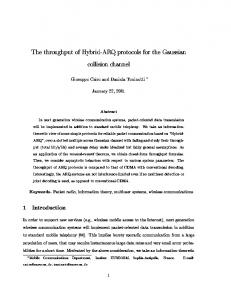
Fig. 1. Temporal diagram of the ARQ scheme when one or more consecutive PDUs are lost and the sender is in saving mode.
entity to require the transmission of missing PDUs and to send feedback information to the transmitter. The loss of a PDU is detected by the receiver either because an out-of-sequence data unit is delivered or no data unit is received by a certain time, �!#" . At the sender, the acknowledged mode involves the use of transmission and retransmission buffers. Upon the reception of a negative acknowledgment, the sender retransmits only the PDUs that have been indicated as missing by the receiver, giving to retransmissions higher priority than data units transmitted �!$%" the delay between the end for the first time. We denote by of a PDU transmission and the reception of the STATUS PDU notifying that the PDU was lost, and by & the number of PDUs �!$%" transmitted during time �!$%" (including the PDUs whose transmission started during ). Moreover, the sender can check on the receiver’s status by polling the receiver until it receives a reply; the receiver must reply to the sender’s poll with a STATUS PDU. In addition to the transfer mechanisms described above, we consider that whenever the sender detects disadvantageous channel conditions, it can enter two different operational modes: greedy or saving mode. In the case of greedy mode, upon the reception of a STATUS PDU notifying that some PDU was lost, the sender retransmits the missing data units at once and then goes on with the information transfer. In the case of saving mode the sender stops transmitting and starts periodically polling the receiver to probe the channel status. The sender starts retransmitting the missing data units only when good channel conditions are detected; i.e., when the sender receives a reply to its poll. The evolution of the protocol in the case of PDU loss and considering the sender in saving mode and &('*) , is illustrated in Fig. 1, where dashed lines represent lost data units. In the diagram on the left side, PDU + is lost and a STATUS PDU trans� ," mission is triggered at the receiver by the expiration of timer . �!$%" After a time interval equal to , the STATUS PDU arrives, the sender ends the transmission of PDU - and stops transmitting. � $%" the sender receives a STATUS PDU inBy time interval
2
dicating that PDU - arrived successfully; thus, the information transfer is resumed and PDU + is retransmitted. In the diagram on the right side, two consecutive PDUs are lost. In this case, the sender receives only the first STATUS PDU indicating that �!$%" PDU+ is missing. After time period , not having received any other STATUS PDUs, the sender starts polling the receiver until the poll transmission goes through and the receiver replies with a STATUS PDU. The missing data units are then retransmitted. Saving mode allows for a better usage of the radio resources as well as of the available energy, since the energy cost of polls and STATUS PDUs are negligible compared to the cost of transmitting PDUs. However, saving mode is less reactive than greedy mode to changes in the channel conditions, and therefore it may cause QoS degradation. In order to dynamically trade-off between QoS provisioning and energy saving, we introduce a control mechanism on the sender such that, if the number of PDUs in the transmission buffer is less than a given threshold .0/ , the sender operates in saving mode, otherwise it enters greedy mode. Under low load conditions which are not critical for QoS provisioning, we privilege energy saving; on the contrary, when queue fills up and QoS deteriorates, we favor QoS provisioning. By varying the value of .1/ , we can easily establish the desired trade-off between energy saving and QoS as radio channel conditions change. III. S YSTEM D ESCRIPTION
AND
A SSUMPTIONS
Let us focus on the information transfer taking place over the uplink radio channel, where, with reference to the ARQ scheme described above, the mobile station acts as sender and the access point acts as receiver. (Notice however that the developed model can represent the reverse situation as well.) We represent the system as sketched in Fig. 2, and we study its behavior by developing a discrete-time Markov chain (DTMC) model, in which the time is slotted according to the PDU transmission time, denoted by 2 .
traffic generator
PDU flow
B
greedy Th
saving wireless channel
transmission buffer retransmission buffer
Fig. 2. System under analysis.
While constructing the ARQ model, the following assumptions are introduced: 1. A single buffer models the presence of both the transmission and retransmission buffers. 2. There is not a maximum number of retransmissions per PDU. 3. STATUS PDUs are always correctly received. 4. The inter-polling time is equal to one PDU transmission time. The model, that we develop, focuses on the following aspects of the system: i) the traffic generator, which represents the arrival process of PDUs to the RLC layer; ii) the transmission and retransmission buffers, although the retransmission buffer is only implicitly represented in the model as is described below; iii) the radio channel; iv) the energy consumption and the battery behavior at the mobile station.
IEEE TRANSACTIONS ON VEHICULAR TECHNOLOGY, VOL. XX, NO. Y, MONTH 2002
TABLE I
A. Traffic Generator and Transmission Buffer
�
�
�
'
�
�
) idle
�
�
'
2 .
and idle
�
� '
) active
' .
2 active
�
(1)
α 1−α
1−β
active
idle
�
�
C HANNEL BEHAVIOR :
The traffic generator is modeled as a discrete-time activeidle Markov process with time granularity equal to the PDU transmission time, 2 . A graphical representation of the process is shown in Fig. 3. During active periods, one PDU is generated during a time slot with probability ; whereas, no PDUs are generated during idle periods. Let . active and . idle denote the average active and idle periods, respectively, and active and idle denote the active and idle periods in slot units: active ' . active 2 and idle ' . idle 2 . Then, the parameters of the traffic generator are
�
3
PROBABILITIES
AND
AVERAGE ERROR PROBABILITY, TRANSITION
, AVERAGE LENGTH OF THE
BURST OF ERRORS ,
�
AND AVERAGE TRANSMIT POWER .
�
0.075287 0.076295 0.122688 0.128128 0.159866 0.175809 0.199287 0.231275 0.265145 0.293261 0.334144 0.372904 0.420459 0.421107 0.455887 0.567886
0.029687 0.022623 0.045430 0.046739 0.056124 0.058466 0.064498 0.077703 0.080407 0.093798 0.099239 0.110713 0.121956 0.122935 0.128343 0.176178
�
0.364635 0.273903 0.324859 0.318043 0.294946 0.274087 0.259145 0.258275 0.222850 0.226047 0.197755 0.186181 0.168098 0.168998 0.153181 0.134057
�
2.742469 3.650927 3.078258 3.144229 3.390451 3.648476 3.858843 3.871842 4.487323 4.423859 5.056763 5.371117 5.948912 5.917230 6.528224 7.459514
� ���
[W] 0.019412 0.019633 0.022188 0.021043 0.022464 0.021279 0.022618 0.021183 0.022584 0.022314 0.022623 0.023179 0.022993 0.023151 0.023001 0.023240
β active
PDU flow
idle
active
probability λ
Fig. 3. Traffic generator.
�
Given that the maximum service capacity of the system (with noiseless channel) is one PDU per time slot, we denote by the traffic load normalized to the system capacity, i.e., the average number of PDUs generated per time slot,
� '� . . � . (2) � . � . � is the probability that the where the ratio . generator is active. Observe that the presence of a single traffic active
idle
active
idle
active
active
generator is justified by the assumption that a traffic segregation policy is employed. Thus, different kinds of traffic generators (in particular loss-sensitive and delay-sensitive traffic generators) are separately treated. Instead of describing both the transmission and retransmission buffers, we model a single buffer from which PDUs are removed only after they are successfully delivered to the receiver. This assumption has negligible impact on the performance measures since retransmissions have priority over new transmissions and, therefore, only a few PDUs are waiting in the retransmission buffer at the same time. B. Radio Channel The radio channel is modeled as a Gilbert channel. Two states, good and bad, represent the state of the channel during the transmission time of one PDU: the PDU transmission is successful if the channel is in state good, and unsuccessful otherwise. We denote the transition probability from state good to state bad by and the transition probability from state bad to state good by ; and have been obtained by using the results in [12]. The procedure adopted is as follows. We consider the channel traces derived in [12] for a WCDMA air interface. As described in [12], channel traces are obtained through a UMTS
UTRA-FDD simulator, which accounts for signal propagation, open and closed loop power control, intra- and inter-cell interference, Doppler frequency, and interleaving. The parameters in input to the simulator are set according to [13]. By using the UMTS simulator, the Signal to Interference plus Noise Ratio (SINR) trace is derived for each simulated user; then, by fixing a SINR threshold, the corresponding sequence of PDU error probabilities is computed for each SINR trace. Let denote the number of samples per sequence (i.e., the simulation duration expressed as number of time slots), the probability of receiving the -th PDU correctly, and the probability of receiving the -th PDU in error. For each sequence of PDU error probability, and are derived as,
�
�� � �� �� � ��� �
�
���
"�(*#%),$'+ & + �-� �� � �-� �� � ) � � � � ) � ' )! (3) " (�#-),$.+ &0/ �%� 1� � � � � "�(*#%),$'+ & + � � �� � � � 1� � ) � � � � ) �
' )! " (�# ),$ + &0/ � � �� � � � � � (4) The average error probability, denoted by 2 , and the � average length� of a burst of errors, denoted by 3 , are derived as � � and ) , respectively.
The results obtained by using the above channel representation were found in good agreement with simulation results, as shown in [14]. As an example, the average error probability, the values of and , the average length of a burst of errors, and the $%" average transmit power for the uplink channel are reported in Table I, for different mobile stations. These results were obtained by assuming thermal noise equal to -132 dBW, the exponent in the path loss model equal to 3.5, log-normal shadowing with standard deviation equal to 4 dB, Doppler frequency set to 6 Hz, the SINR threshold fixed to 6 dB, and Rayleigh fast fading [12].
�
C. Energy Consumption and Battery Behavior We consider both the energy consumption at the mobile station due to the transmission of data units and the phenomenon of
IEEE TRANSACTIONS ON VEHICULAR TECHNOLOGY, VOL. XX, NO. Y, MONTH 2002
VALUES OF ENERGY GAIN ��
�
TABLE II AS THE MOBILE STATION TRANSMISSION RATE VARIES .
Transmission rate
��
0.1
0.2
0.3
0.4
0.5
2.1
1.4
0.92
0.65
0.43
charge recovery, which takes place in real batteries during idle periods. The energy consumption per PDU transmission is computed $%" $%" 2 , where as is the power consumed by a mobile station in transmitting mode. Clearly, the energy consumption per information data unit transfered over the radio channel increases with the increase of the number of PDU retransmissions. On the contrary, charge recovery may lead to a significant improvement in battery lifetime when a pulsed discharge is implemented instead of a continuous discharge [15], [16]. As shown by several experimental tests [17], [18], [19], [16], the performance gain due to this phenomenon depends on the amount of time spent by the mobile station in idle state. The lower the radio terminal activity rate, the greater the improvement in battery lifetime obtained through pulsed discharge. ��� To account for charge recovery, we define the energy gain as the ratio of the total amount of available energy at the radio terminal when a pulsed discharge is applied to the amount of energy available in the case of continuous discharge. By considering that the transmission of a packet is the operation with the highest energy cost, we take the terminal activity rate to be equal to the number of PDU transmissions per time slot. In Table II, ��� obtained in the case of a lithiumwe report the values of ion battery as the PDU transmission � � rate of the radio terminal varies; as an example, a value of equal to 1.4 corresponds to a gain of 40% in battery lifetime relatively to the case where a continuous discharge is performed.
�
�
IV. A NALYTICAL M ODEL In this section, we describe the DTMC model for the case �!$%"��*�!#" . Extensions to large values with & equal to 1; i.e., of & will be discussed at the end of this section. In order to model the system behavior, the following dynamics have to be carefully described: i) the PDU generation process, ii) the buffer occupancy, iii) the working mode of the transmitter, and iv) the channel state. Accordingly, let the DTMC state be defined by the vector
&
4
&
'�
������ � � � �� ����� ��
where � is the state of the traffic generator; can assume two values only which represent the activity and the idle periods of the traffic generator, respectively denoted by � and � : ����������! ; � � is the transmission buffer occupancy in number of PDUs (remember that � includes the PDUs in the retransmission buffer), �� can � assume all integer values between 0 and " ; is the state of the transmitter, either active or idle; when active, the transmitter is sending PDUs over the radio channel; on the contrary, the transmitter is idle when it has no PDUs to transmit or when, being in saving mode, it has detected bad channel � conditions, ���������# ;
�
&
&
in slot $ the value of � denotes the state that the transmitter ) , �%�&�'���# ; assumed in slot $ � � � is the channel state, ���%�( *)+)+,-���/.*,# ; in slot $ the value of � denotes the state that the channel assumed in slot $ ) , � �%�( *)+)+,-���/.*,# . Observe that, in order to properly take into account the delay between the transmission of a PDU and its acknowledgment, the introduction of some memory about the past history of the � system is necessary; therefore, we introduced the variables and � . &� 10 denote the probability that the chain moves in Let � � one-step from source state ' ��� � � ��� ��� to desti� � nation state 0 ' 0 �2� 0 � 0 � 0 ��� 0 ��� 0 . In determining proba &� 10 ’s notice that the behaviors of the channel and bilities of the traffic generator are independent of the rest of the system; thus, their stochastic description can be a-priori specified by input parameters. On the contrary, changes in the transmitter mode and in the buffer occupancy can be deterministically derived from the actual state of the system and from the channel and generator behavior. Hence, we write the following expressions
&
&
&
&
� � � � � �
� & � & � � �& � �& � �
� �� � *0 � ' 3� �&�546� �879� 0 ;: �3�< =4� �>7? 0 1: @ 0 � : A &� � *0 � (5)
where �
that the channel state �B�&�546� �>79� 0 is0 the probability changes from � � to � , with � ����� 0 �C�( *)+)+,-���D.1,# ; � �B�< =4+ � 7E 0 is0 the probability that the traffic generator changes � from � to , with � �F 0 ���������# ; � @ 0 � is the probability that a PDU is generated in state 0 ; A �&� G0 � is an indicator, which is equal to 1 if state !0 is a possible successor of state � ; and equal to 0 otherwise. � �(�546� � 7H� 0 , 3� �D �4+ � 7E 0 and As already mentioned, 3 0 @ � are independent of the state of the system. The value of � changes according to the two-state model of the channel,
�3�(�546� �
79� 0
K '
IJJ
JJL
! )
!
if � if � if � if �
)
� � � �
'M G)+)+,�NO� 'M G)+)+,�NO� 'R�/.*,�NS� 0 'R�/.*,�NS� 0
0 'P *)+)+, 0 'Q�/.*, 'P G)+)+, 'Q�/.*,
�
(6) Changes in the state of the traffic generator (see Fig. 3) determine changes in the value of ,
�
�
B���54+ 87? 0 '
K JJL
IJJ
�)! � )! �
�
if if if if
� � � �
'T��N� 0 'T��N� 0 'T�BN� 0 'T�BN� 0
'Q� ' � Q 'Q� 'Q�
�
(7)
According to our traffic model, when the generator is active, a new PDU arrives at the buffer with probability ,
�
@ 0 'VUXW
if if
0 'Q� 0 'Q�
�
�
(8)
Table III reports the transitions from state to its successors *0 , with A �� *0 ' ) . In the Table, the third column denotes the conditions that states and *0 have to satisfy in order to have A � 0 '*) . Notice that not all the possible transitions
� � � �
�
IEEE TRANSACTIONS ON VEHICULAR TECHNOLOGY, VOL. XX, NO. Y, MONTH 2002
5
TABLE III ��� P OSSIBLE ONE - STEP STATE CHANGES FROM STATE ���� � �� � �� �� �� �� � ������������ � � State �� ���
��� �� � ��� ��� ��� ���
�� %� Successor $ �%$ �����!� $ ��!���� ������� � ��� ��(�� ��!���� �����)� � ��� �������!���!���� $ ����� � � �%$ � �� �,$ + (�� �� � ��� � ��� � � ��� �� � � $ �� �$ � ��� ������� � �%$ ���� � � � $ ��� $ ������� � ��� �� �98 (�$ � � ��� � ��� � � �%$ � �� � ��!�� ��� $ � ��� � � ��� �� � 8 $ (���!�� ����� �� "*"�����# � � � � � �
� � � � � ! � � � � � � �%$ $ � "�� "�# � ��� �� �98 (�� ��!���� ��# � � � � �
� � � � ! � � � ! � � � � � � �
: � �%$ # �%$ �� � 8 $ (���!���!���� ����# : � �%$ ��2 4 � $ ��!� $ ��� ���� : � ��� ��2 4 � $ � $ ����������� � �%$ � �� � � � $ ��$ � � ��� � � ��� �� 8 $ (�� $ � ����������� � ��� ����D=� � $ ��� ��$ ��� � � �%$ � �� �,$ + (�$ � � ��� � ��� � � �%$ �� � � � $ ��� �� $ ���)� � ��D + (�� � ��� ������� �
� "�"�# �������!���!�������� � $ ��"*"�# � � (���!�� $ ��� � � � "�"*� # � �� � �� � � ��� � � � $ � "�"�# ���� ��� ��!�������� � $ $ # � �� � � � ��� � �� : � � "�"�# ���� ����!��� �� � � ������ � � # ���� ����!��� �� � �� : � ���, � �
��� �� � �� ��2 4 + �� � �� ��2 4 $ + � �� � � ��� $ ��� � ��D6� $ � �� � � ��� $ ����D6�
# (���!� �# � $ �� �� � �� : ������ (�$ � �� �� � ��#������ : � � ��� � �� : � $ # � $ ��� � �� ��: "*"�� # � ��� � � � $ � "�"�# � ������� �
are listed in the Table. Transitions corresponding to losses are explicitly indicated. � The state variables and � are, by definition, determined � by the value of and � in the previous slot, so that for each � � transition from state to 0 , we have 0 ' and � 0 ' � . � Changes in the value of and � depend deterministically on the channel and generator behavior, as well as on the current state. Let us first focus on the saving mode of the transmitter. Since & ' ) , the transmitter chooses its working mode according to the most recent estimate of the channel state, which is the value of � . If during slot $ , while the transmitter is active and sending a PDU, a STATUS PDU arrives notifying that the PDU sent in slot $ ) is missing, the transmitter completes the current PDU transmission, and switches to idle at the beginning ) . Thus,� as reported in Table III, in saving mode of slot $ from states with ' � and � ' �/.*, the chain moves � to states with 0 ' � . On the contrary, if the transmitter is idle in slot $ , it sends a short poll message at the beginning of slot $ , receives a STATUS PDU still in slot $ and switches to active at the beginning of slot $ ) . These are the transitions � from states with and � ' *)+)+, , to states *0 with ' � �0 'Q� . When in greedy � mode, the transmitter is always active. Therefore, states with 'R� and �FE W are not possible. The buffer dynamics are governed by the PDU generation process and by the successful transmission of PDUs over the radio channel. In particular, during a transition from to 0 a PDU is generated with probability @ 0 ' if the traffic generator in the destination state is active (states with 0 ' � ). A PDU is successfully transmitted if the transmitter is active and the channel is good. However, as mentioned above, a successful PDU transmission in slot $ ) is notified during slot $ , and the PDU is removed from the buffer only at the beginning of ) . Thus, during a transition from to 0 , a PDU is slot $ � ' � and � ' *)+)+, . Finally, removed from the buffer if we adopt the convention that at the beginning of a slot, the generation of a new PDU precedes the removal of a PDU from the buffer. This implies, for example, that the transition from state
&
&
&
�
&
�
&
� � �
�&
�
��
�
�
�
�
�&
&� �
�
���
TO STATE
���
���� ����� ����� �� � ����������� � � .
Condition �
&
�
& � &
� & �
& � & � &
�
& � & � & � & � & � & � & � & � & � &
�'��������� � � � � � ����� � ��� � � � � � ��� � ��� � �� �.- (0/1 � /3254 � � � �'� �����)����� � - 6/7 ��/32 4 � � � � � � ��� � ��� �,� - 6/7 � /3254 � �'��������� � � - 6/7 �;/E W ; the PDU is the slot duration. By expressing
size is equal to ����� , 2 ����� as bits and 2 as milliseconds, � is the throughput in Kbps. The PDU loss probability � is the probability that a PDU can not be accommodated in the buffer. We compute �� as the fraction of PDUs which are lost. The sum of the probabilities
�
�
� By considering that a PDU transmission time is equal to 10 ms and the peak data rate is equal to 384 Kbps, we have ������� �!#"%$'&)(+*-,�� . +/ �(0< , � $1"' bytes.
6
of the transitions in which a PDU is lost represents the average number of PDU which are lost during a time slot. In a time interval of $ slots, the average number of lost PDU is equal to this sum multiplied by $ . In the same time interval, the average number of PDUs arriving at the buffer equals $�: , where is the normalized traffic load as defined in (2). Thus, �� is given by,
�
�
� '38:25979� 0 : �< =4� 87E 0 . By ordering states according to Q as in (9), we collect in the row vector �*' ��� the probability that the buffer empties from state , with ' )6��NG�(: