Impact of Software Fault Tolerance to Fault Effects in OS-Driven RT Systems. 759 the timeliness is not affected. There are many techniques belonging to the FT.
Computing and Informatics, Vol. 33, 2014, 757–782
IMPACT OF SOFTWARE FAULT TOLERANCE TO FAULT EFFECTS IN OS-DRIVEN RT SYSTEMS ˇ´ık Josef Strnadel, Frantiˇsek Slimar Brno University of Technology, Faculty of Information Technology IT4 Innovations Centre of Excellence Boˇzetˇechova 2, 612 66 Brno, Czech Republic e-mail: {strnadel, islimarik}@fit.vutbr.cz
Abstract. Real-time kernels are often utilized to simplify the design of embedded time/safety-critical applications. However, embedded systems are sensitive to transient and other faults, each of which can lead to various errors at various system levels and can potentially result in system failure. In existing works, the real-time kernels sensitivity to transient SEU errors was studied only with the goal to classify SEU impacts to system behavior. In this paper, the study is extended to permanent faults being injected into the persistent program (firmware) memory and into the volatile data memory. Moreover, it is studied there how the sensitivity is affected if combination of software fault-tolerant techniques is built into various levels of the system. On the experimental basis, it is shown that some fault impacts are difficult to be softened by common fault-tolerant techniques. Keywords: Fault, effect, error, fault tolerance, real time, operating system, kernel, task, software, firmware Mathematics Subject Classification 2010: 68M15, 68N25
1 INTRODUCTION Many systems exist, which need to satisfy stringent constraints being derived from systems they control. The paper is dedicated to the systems, perfection of which is based on both the correctness and the timeliness of the outputs [7, 8, 17]. A system able to produce the correct response to given stimuli on time is called a real-time (RT) system.
758
J. Strnadel, F. Slimaˇr´ık
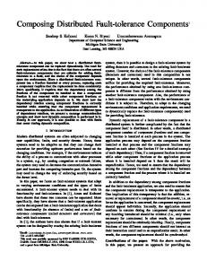
1.1 Real-Time Operating Systems High complexity of many RT applications has made the adoption of RT operating systems (RTOS, RT kernels) to simplify the application design [8, 7]. RT applications running over an RTOS can be designed by the means of mechanisms [17] able to manage crucial resources such as time, memory, tasks etc. Thus, an RTOS can be seen as an abstraction layer between an application software (SW) and a platform hardware (HW). In this paper, it is supposed the application is embedded and its HW is realized by a microcontroller unit (MCU). For the abstraction, an RT system is typically modeled as a set (Γ = {τ1 , . . . , τn }) of n RT tasks, each of which (τi ) is described by the parameters such as priority (Pi ), release time (ri ), worst-case execution time (Ci ), period (Ti ) and response deadline (Di ) required by a scheduling policy able to organize the task executions in such a way the timeliness of responses produced by the tasks is guaranteed [8]. 1.2 Fault Tolerance As embedded systems are sensitive to many faults, each of which potentially results in the system failure, proper fault-tolerant (FT) techniques must be built into such systems. A failure characterizes wrong service delivered by a system, i.e., actual behavior that is not in compliance with the expected behavior. A fault, i.e., a deviation in a component from its intended function, is a failure case and can manifest itself as an error. Faults can be classified in several ways, e.g., by their duration as permanent, transient and intermittent [4]. However, latencies related to the techniques (Figure 1) can cause a significant problem if they are involved in RT systems. It is because efforts of the techniques can result in a situation in which timing of the reactions does not comply with the system specification. Especially in the area of critical systems it holds that any violation of the system specification (i.e., a failure) can have serious consequences [11] during the system runtime. Fault
Error Fault latency
a s-a-0 fault occurs
Error detection Error latency
1 written into the bit with the s-a-0 fault
Recovery/Failure
Fault tolerance mechanism latency
wrong value (0) read instead of correct value (1)
System reaction latency
service execution continues or fails
system reaction to failure (fail-safe, fail-stop, fail-operational)
Figure 1. Typical latencies related to dependability mechanisms
As RT systems can be considered to be a subclass of critical systems, then a subset of FT techniques must be applied in a way that faults are mitigated while
Impact of Software Fault Tolerance to Fault Effects in OS-Driven RT Systems
759
the timeliness is not affected. There are many techniques belonging to the FT group (e.g., fault masking, recovery, correction). In fact, all of them are inspired by the redundacy concept applicable at both the HW and the SW levels of a system. Basically, the redundancy can be clasified to spatial redundancy and time redundancy classes. Within the spatial class, the following sub-classes can be distinguished: • technical redundancy realized in the HW part of the system (e.g., N-modular redundancy), • information redundancy realized in the data part of the system (e.g., detection/correction codes) and • program redundancy realized in the SW part of the system (e.g., control-flow checking). The techniques from the second class (i.e., inspired by the time redundancy concept) are typically based on the re-execution of HW and/or SW actions that previously resulted in an error. The paper is focused on techniques applicable mainly at the SW level – those can be divided to kernel-level and task-level techniques. 1.3 Structure of the Paper The paper is organized as follows. In Section 2, key terms related to the paper are presented such as classification of effects and misbehaviors induced by faults (2.1), existing works representatives (2.2) and motivation and goals of our research (2.3). Experimental framework details related to operating system, development platform, FT techniques, fault injection principle and types of experiments performed in relation to the paper are presented in Section 3. Section 4 summarizes the experimental results and Section 5 concludes the paper. 2 DETAILED BACKGROUND OF OUR RESEARCH Operating systems (OS) dependability has been studied for more than three decades [9], but remains a major concern today [35]. 2.1 Fault Effects OS errors can be caused by faults such as programming bugs, aging, temperature or other phenomena induced by the system environment such as radiation-induced bit-flips in memory and registers, called Single Event Upsets – SEU s, and many others [15]. The error caused by an SEU fault (strike) is called an SEU or – maybe more frequently – a soft error (SE ). Functionality of a system is not permanently damaged by a SEU, unlike by single event latchup, single event gate rupture, or single event burnout, which are examples of other radiation effects observed in electronic devices. Such effects are typically grouped into a single event effect class. In relation
760
J. Strnadel, F. Slimaˇr´ık
to RT systems, SEs – which are typically of transient behavior – can temporarily affect an RT application as well as an RTOS over which they are executed. 2.2 Representatives of Existing Works Several solutions have been proposed to deal with reliability w.r.t. embedded RT systems controlled by an RTOS. In [2, 14], the problems are solved at the scheduler level in order to improve robustness of RT embedded systems. In [28, 18], checkpointing with rollback recovery and active replication is implemented to tolerate SEs at the application (i.e., SW) level. In [37, 10], techniques able to detect and correct control flow errors without a program interruption are presented. Different SW approach based on an introduction of additional tasks responsible for checking other tasks is presented in [31]. Another principle is inspired by microrebooting [6]: recovery from a microkernel failure is realized by restarting it – the main idea is that reinitializing data structures by restarting them usually fixes a transient fault. Further technique, able to automatically identify runtime failures, locate faults, and find a way to bring the system back to an acceptable behavior can be found in [12]. On top of the SW solutions to the problems, several HW solutions exist. For example, in [19] a special HW/SW architecture is presented making services robust in term of SEs; two approaches are presented, each of which offers feasible solution for a given limited amount of resources: the first one assumes that the error detection is deployed on static reconfigurable FPGAs, while the second is based on partial dynamic reconfiguration capabilities of FPGAs. Further approach, based on a HW scheduler able to detect faults changing tasks execution times and/or execution flows can be found in [36]. In [27], a hardware-based RTOS-Guardian (RTOS-G) intellectual property core designed to monitor the RT-task executions in order to detect faults was presented. Also, many special RT kernel frameworks such as model-driven [20] or common RT kernels such as [29] were developed to simplify the design of dependable embedded RT applications either by means of a special model utilized for the purpose or by narrowing the set of kernel functions. Special works are related to design or selection of a fault injector utilized to check properties of the proposed reliability solutions; well-written summary related to the fault injection concepts can be found in [5]. 2.3 Motivation and Goals of Our Research We decided to limit the research related to this paper to the approaches applicable at the SW level [30, 33]. We did so because we found that these approaches suffer from many shortcomings – especially, they have focused to SEU effects only and/or tried to mitigate the SEU effects using a single FT technique embedded either into the task or the kernel level of an RT system. At this point, it should be noted that 1. transient SEUs are not the only faults which can impact embedded systems, 2. the fault effects can manifest themselves at various system levels and
Impact of Software Fault Tolerance to Fault Effects in OS-Driven RT Systems
761
3. multiple FT techniques can be built into various system levels to mitigate propagation of the fault effects. Our research w.r.t. this paper was motivated maily by the fact that fault effects induced by multiple fault types are not studied in context of FT mechanisms implemented at various RT system levels. Typically, embedded systems are realized on the basis of a microcontroller (MCU) or a field-programmable gate array (FPGA). Among others, such systems can be prone to high-level faults such as bugs introduced by a human programmer or faults related to communication interfaces able to update the device firmware. In FPGA based systems, the latter faults can lead to an unwanted bitstream or memory change causing permanent or temporal system behavior errors; but, effects of bitstream-related faults are usually minimized because of bitstream-checking mechanisms typically present in many FPGAs. In MCU based systems, a fault can be manifested by change of a program being updated by a bootloader interface. Here, the situation is worse than in the FPGA area because MCUs are not typically equipped with similar firmware-checking mechanisms. As a result, practically any sequence of bytes can be programmed into MCU’s flash provided that a fault is injected to flash-cell contents, but not to the robust flash access control protocol. The above-mentioned facts (especially those related to MCU area) have motivated us to set the following research goals: • to define a set of FT techniques suitable for implementation into an embedded RT system controlled by an RTOS. Each of the techniques has to lead to a deterministic and short time overheads as they are important to avoid the decrease of an RT system reactivity, • to define RT system parts which are the most critical from the overall point of view to an RT application and to select a set of suitable FT techniques to increase dependability of the parts, • to design and realize an RTOS-driven FT architecture, experimentally verify its impact to distribution of effects induced by various types of faults introduced into various parts of the system and finally, to interpret and sum achieved results. 2.4 Main Idea of Our Experiments To achieve the goals specified in Section 2.3, we have decided to utilize the experimental framework configured as follows (for an overview, see Figure 2). The faults of the following classes were introduced (and their effects were observed) during experiments: transient (such as bit-flip in a memory element), permanent (such as programming error) and firmware (such as illegal operating code or address) faults. Each of the faults, being introduced to low-level parts of the embedded system (such as CPU registers, memory cells or RT kernel structures from Table 1), can manifest itself as an error at higher levels of the system (such as OS service calls, task/memory management services or data/timing misbehaviors).
762
J. Strnadel, F. Slimaˇr´ık
FI manager
Seeddriven FI control
Tasks
MCU
BDM FI seed generator BDM controller Fault effect analyzer
Fault effect
uC/OS-II
CPU
RAM/ Flash
Figure 2. Overview of the experimental framework utilized w.r.t. the paper
In [24, 23] the following error classes were distinguished: effectless, application hang, exception, memory, access malfunction, system crash, incorrect output results, realtime problems (timing errors), scheduling malfunctions (task scheduling errors). In relation to this paper, it was decided to take the above-mentioned classification as a basis for our experimental setup. The goal of our experiments was to study the relation among injected faults, fault effects and FT techniques implemented into the system. First, the effects were observed at the kernel-level only to observe their impact to the kernel (OS services) behavior, i.e., independently from the application realized (related experiments are denoted as kernel-level experiments in Sections 3.4 and 4). Afterwards, the effects were observed at the application (task) level to observe impacts of their propagation up to the level (related experiments are denoted as Task-level experiments in Sections 3.4 and 4). For the the latter (applicationspecific) experiments special sorting application was created to show the propagation effects. For the fault-effect and error detection purposes, the embedded application was designed in a way it would be possible to (dis)activate a given combination of fault-tolerant techniques in selected portions of the embedded system – details to the implemented techniques can be found in Section 3.2. Experiments were driven and evaluated by a PC. The PC was utilized as 1. storage for descriptions of faults to be injected into the system and 2. storage of observed fault effects. The fault-description list is generated randomly and for each of the faults; the following information is stored there: injection time (in µs), fault type (transient, permanent, firmware) and fault location – for details related to the fault-list encoding, see Section 3.3. Our embedded system (for details, see Section 3.1) utilized as an RTOS-driven basis for the experiments was running on a microcontroller unit (MCU). The MCU is equipped with the background debug module (BDM) operating in parallel with the CPU, both implemented on chip of the MCU; the BDM can be utilized to read the state of an embedded application at runtime or to stop the application in a predefined time in order to change a register/memory content (i.e., to inject a fault in our case) and afterwards to resume the run of the system.
Impact of Software Fault Tolerance to Fault Effects in OS-Driven RT Systems
763
The injection principle can be summarized as follows. After the PC is initialized and the fault-list becomes ready, the MCU is reset and run until the forthcoming injection time. At the time, a fault is injected into the embedded system according to the information stored in the list. Let it be noted there that just one fault is injected at a time. Then, the MCU is started to run until the farthest task deadline is over. In this interval, behavior of the application is monitored by the PC via the BDM interface (running in parallel with the application code) – any unexpected behavior of the application such as wrong (late, no) data/reaction or reset because of wrong memory access or illegal operating code etc. is stored on the PC side. After the deadline is over (or after the MCU is reset because of the fault) the next fault is read from the list and the MCU is reset (if not done so yet) and run until the forthcoming injection time. Details related to the experiments can be found in the following section. 3 EXPERIMENTAL FRAMEWORK 3.1 Platform Details For the experiments, it was decided [30, 33] to utilize the µC/OS-II kernel [16, 22] running on the 8-bit MCU embedded in the Freescale DEMOQE128 board [21]. The kernel was chosen due to the following reasons. First, it was because of inherent properties of the kernel – it is a portable, scalable, multitasking, preemptive, deterministic RTOS that is freely available in a well-documented source-code form (for non-commercial and peaceful purposes only). Second, it is robust, reliable and since 2000 it is certified by the Federal Aviation Administration (FAA) for use in safety-critical systems. Third, many works in the area based their experiments just on the kernel [3, 13, 26, 32, 37]. The board was selected because of its BDM support and its USB port allowing easy connection to a PC in order to drive the experiments. 3.2 Selected Software Fault-Tolerant Techniques Since this article considers the implementation of FT by means of SW then it was necessary to select representative techniques from the software FT group before experiments can be performed. Because it generally holds that FT techniques are based on the redundancy concept, it was decided [30, 33] to select their representatives on the basis of the corresponding redundancy type. In the SW area, two redundancy types are typically utilized: time redundancy and program redundancy, each of which can be realized by means of forward and backward recovery mechanisms. The following representatives of software FT techniques were selected for the experiments w.r.t. the paper: N-version programming technique (3.2.1), Primary backup technique (3.2.2), Control flow checking technique (3.2.3) and SW Watchdog technique (3.2.4). Principle w.r.t. each of the representatives is summarized below, followed by description of its setup in the experiments.
764
J. Strnadel, F. Slimaˇr´ık
3.2.1 N-Version Programming This technique (inspired by the technical N-Modular Redundancy, NMR) is based on the following design diversity principle (see Figure 3 a)): to solve a problem, n different algorithms are implemented as separate tasks, each of which is able to generate the correct solution (output) to a given instance of the problem (input). After the results are produced, they are analyzed by the voter (selector ) for both their correctness and timeliness. Experiment setup: During our experiments [30, 33], the problem of sorting a kelement array (k = 1 000) of 32-bit integers was solved by means of 3 different sorting algorithms (Bubble sort, Counting sort and Insertion sort). All the algorithms, as well as the voter were implemented to run independently (i.e., in separate address spaces). Since MCU present in the Freescale DEMOQE128 board does not contain an on-chip memory management unit able to separate memory spaces of the 3 running tasks, 3 boards were utilized each of which running one of the tasks. For communication (synchronization) of the tasks, shared memory (mutexes) were utilized. The voter was designed either to output an array which was both sorted correctly and on time or to signalize an error to its superior module. Also, overall statistics (incorrect output ratio, deadline miss ratio) were collected by the voter. In order to automate the experiments, the voter was designed so that it was able to generate new input data just after the output to last input was produced by the tasks. 3.2.2 Primary Backup This technique is based on the data diversity principle and can be described as follows (see Figure 3 b)). Two identical implementations (primary, secondary) of the same task are executed on the same platform in order to achieve high availability of a service despite an error is detected in one of the tasks. While the primary task is active – i.e., able to provide its service as well as to backup its correct state – the secondary task is inactive. If an error is detected by the Switch task then the primary task is suspended, the backup memory is read by the secondary task and the service starts to be provided by the secondary task, which becomes primary and active now. Thereafter, the functionality of the suspended primary task can be tested. If an error is not detected during the testing, the task becomes secondary; otherwise, it must be replaced by an error-free version (moved to a different memory space, reinitialized etc.). Experiment setup: In our experiments [30, 33], the tasks were designed to sort a k-element array (k = 1 000) of 32-bit integers. Both the correctness and the timeliness of results produced by the primary task was checked by the Switch task responsible for switching from an erroneous primary to an error-free secondary task. To minimize the overhead w.r.t. switching between the tasks, backup states are stored
765
Impact of Software Fault Tolerance to Fault Effects in OS-Driven RT Systems backup signal i n p u t d a t a
sync.
Method_A
Primary task
state
error
result result
Method_B
Backup memory
Voter
Switch result
result
state
Method_n result
start/stop
start/stop
input data error
Secondary task
read signal
a)
b)
Figure 3. An illustration to a) N-version and b) Primary-backup programming
into a shared memory with access synchronized by means of mutexes. Moreover and w.r.t. the experiments the Switch task is responsible to 1. produce arrays to sort, 2. signal the correct and on time outputs or an error signaled to the superior module and 3. collect statistics such as incorrect outputs ratio and deadline misses ratio. 3.2.3 Control-Flow Checking (CFC) The principle of this technique can be summarized as follows. The program (code) to be checked for the control-flow (CF) corectness is decomposed into basic blocks first. Each such block (Bi ) is the longest continuous sequence of non-branch instructions within the code. So, each program (P ) can be described by means of the program graph GP = (V, E), whose set of vertices (V ) contains all Bi s of P and whose set of edges (E, where E ⊆ V × V ) contains edges (Bi , Bj ) ∈ E, each of which represents an allowed (valid) transition from Bi to Bj . The method variants differ in the way they check validity of the transitions at runtime. For example, the Enhanced Control-Flow Checking Using Assertions (ECCA) method [1] assigns a unique prime (BIDi , block identifier) to each of a program Bi s along with the NEXTi value equal to product of BIDs of all valid successors of Bi in the program. The global variable (id) is utilized to store results of the SET (TEST ) operation performed at the beginning (end) of each Bi . Wrong CF leads to division by zero. Similar principle can be found w.r.t. the Control-Flow Checking by Software Signatures (CFCSS) method [25]. It assigns a unique identifier bi (prime values are not required) to each of the program blocks (Bi ) along with the di value equal to the difference of a valid bi ’s predecessor (Bj ) and bi – i.e., di = bj − bi . The transition from block Bj to block Bi is valid if (Bj ⊕ di ) = bi holds, where ⊕ is a symbol representing the binary xor operation.
766
J. Strnadel, F. Slimaˇr´ık
01 void OS_Sched (void) 02 { 03 /* --- B1 (block #1) --- */ 04 OS_ENTER_CRITICAL(); 05 if (OSIntNesting == 0) { 06 /* --- B2 (block #2) --- */ 07 /* Schedule only if all ISRs done and ... */ 08 if (OSLockNesting == 0) { 09 /* --- B3 (block #3) --- */ 10 /* ... scheduler is not locked */ 11 OS_SchedNew(); 12 if (OSPrioHighRdy != OSPrioCur) { 13 /* --- B4 (block #4) --- */ 14 /* Ctx-sw if current task is not the HPT */ 15 OSTCBHighRdy = OSTCBPrioTbl[OSPrioHighRdy]; 16 OSTCBHighRdy->OSTCBCtxSwCtr++; 17 OSCtxSwCtr++; /* Increment ctx-sw counters */ 18 OS_TASK_SW(); /* Perform a ctx-sw */ 19 } 20 } 21 } 22 /* --- B5 (block #5) --- */ 23 OS_EXIT_CRITICAL(); 24 } a)
Experiment setup: In our experiments [30, 33], the techniques were implemented into the following µC/OS-II kernel functions: OS Init() designed to initialize the kernel structures, OS Sched() performing the scheduler function, OS Sched- Lock() able to lock the scheduler, OS SchedUnlock() able to unlock the scheduler, OS TimeTick utilized to manage the operating system time. Let their implementation be demonstrated on OS Sched() only – the original code of OS Sched() can be seen in Figure 4 a) while the corresponding CF graph can be seen in Figure 5. It can be seen in Figures 4 and 5 there are 5 blocks (B1 , . . . , B5 ) and 7 valid (allowed) transitions among them in total. The node marks assigned to each of the blocks are visualized in Figure 5 (BIDs/NEXT s for ECCA together with bi s/bj s for CFCSS technique). Because of limited space in the paper, it is only illustrated how the CFCSS is implemented in each of the blocks (Figure 4 b)). 3.2.4 Watchdog Task This technique is inspired by a common embedded instrument, which is an on-chip HW module – running in parallel with an on-chip CPU – called watchdog (WDG)
Impact of Software Fault Tolerance to Fault Effects in OS-Driven RT Systems
767
01 void OS_Sched (void) 02 { 03 OS_ENTER_CRITICAL(); 04 /* B1 */ 05 GSched=b1; 06 if (OSIntNesting == 0) { 07 /* B2 (src: B1) */ 08 CheckFlow(&GSched,b2,d12,NULL,0); 09 if (OSLockNesting == 0) { 10 /* B3 (src: B2) */ 11 CheckFlow(&GSched,b3,d23,NULL,0); 12 OS_SchedNew(); 13 if (OSPrioHighRdy != OSPrioCur) { 14 /* B4 (src: B3) */ 15 CheckFlow(&GSched,b4,d34,NULL,0); 16 OSTCBHighRdy = OSTCBPrioTbl[OSPrioHighRdy]; 17 OSTCBHighRdy->OSTCBCtxSwCtr++; 18 OSCtxSwCtr++; 19 OS_TASK_SW(); 20 } 21 } 22 } 23 /* B5 (src: B1, B2, B3, B4) */ 24 CheckFlow(&GSched,b5,d15,Dsched,(INT8U)3); 25 OS_EXIT_CRITICAL(); 26 } b) Figure 4. µC/OS-II scheduler – a) the original and b) its CFCSS modification
or computer operating properly (COP ); we outlined its principle in [34]. Principle of the WDG module can be described as follows. After the WDG module is enabled its inner free-running counter is reset and then started. If the WDG module is not signaled before the counter reaches its maximum value (i.e., before it overflows), the MCU is reset with no chance for backup, recovery or graceful degradation of its operation. Otherwise, the free-running counter is reset only, so new WDG timeout is set. In other words, an embedded application must be written in such a way the WDG module is signalled on time, i.e., before its WDG timeout is over. The WDG module is typically utilized to exit an embedded system from the deadlock state, in which the probability of sending the signal is very low. As the consequence, the deadlocked system is reset and afterwards it starts to run from its initial state, which is supposed to be deadlock-free.
768
J. Strnadel, F. Slimaˇr´ık b1 = 0001 BID = 3 NEXT = 65
B1
b2 = 0010 d12 = 0011
B2
BID = 5 NEXT = 91
b3 = 0011 d23 = 0001
b5 = 0101 d15 = 0100
BID = 7 NEXT = 143
B3
b4 = 0100 d34 = 0111
B4 BID = 11 NEXT = 13
B5
BID = 13
Figure 5. µC/OS-II scheduler CF graph with ECCA/CFCSS node labels priority
WDG_i_TIMEOUT
WDG_i_TIMEOUT
WDG_i_TIMEOUT
WDG_i_TIMEOUT
WDG_i_RST
WDG_i WDG create (1)
task_i
WDG_i_REC
WDG execution (Wi)
(2) WDG wait
WDG (3) delete WDG (4) reset
(5) WDG create
WDG overflow (7) (6) WDG wait
TASK recovery (8)
WDG_i_TIMEOUT
WDG (9) delete WDG (10) reset
task execution (Ci)
error-free task
task period (Ti)
faulty task
recovered task
t
task period (Ti)
Figure 6. WDG process (WDGi ) illustration: error-free, faulty and recovered tasks
Experiment setup: In relation to our experiments [30, 33], the technique is implemented as follows. Each RT task (τi ) of priority Pi , where i ∈ N is assigned a WDG task (WDGi ) of priority PWDG i > Pi . WDGi must be started along with τi release to activate the mechanism able to recover on time from eventual malfunction of τi . The behavior of WDGi can be described as follows: first, WDGi waits for a τi specific number of time units (WDG i TIMEOUT ≤ Ci ) for the reset signal sent by τi . If the signal is received before the timeout expires then WDGi is reset, τi is checked for omission/value errors and the next timeout is adjusted (Figure 6, steps 1 to 4). If an error is detected or WDGi is not reset on time, the recovery mechanism is initiated (Figure 6, steps 7 to 10).
Impact of Software Fault Tolerance to Fault Effects in OS-Driven RT Systems
01 static void task_n_watchdog (void * p_arg) 02 { 03 INT8U err; 04 void *msg; 05 06 for(;;) 07 { 08 msg = OSMboxPend(msg_WDG_n, WDG_n_TIMEOUT, &err); 09 if (msg != (void *)0) /* -- WDG reset on-time -- */ 10 { /* check for omission and value faults, */ 11 } /* then reset SYS_WDG */ 12 else 13 { /* -- WDG timeout over -- */ 14 if (msg != (void *)0) 15 { /* initiate recovery mechanism */ } 16 } 17 } 18 } a) 01 static void task_n_body (void *p_arg) 02 { 03 OSTaskCreate(task_n_watchdog,/*WDG task creation*/ 04 (void *)0, 05 (OS_STK *)&task_n_wdg_stk[TASK_WDG_STK_SIZE-1], 06 TASK_n_WATCHDOG_PRIO); 07 08 for(;;) /* -- code of the task -- */ 09 { 10 /* init data */ 11 /* perform function */ 12 /* create check & restoration points */ 13 /* produce output */ 14 OSTimeDly(TASK_n_PERIOD);/*wait for new period*/ 15 } 16 17 OSTaskDel(TASK_n_WATCHDOG_PRIO);/* WDG deletion */ 18 } b) Figure 7. Illustration to a) WDGi and b) τi implementations under µC/OS-II
769
770
J. Strnadel, F. Slimaˇr´ık
3.3 Fault Injection In order to control the fault occurence process, a fault injector (FI) is typically implemented. So it is done in relation to this paper. The FI implementation can be done in HW or SW; during our experiments [30, 33], the latter (SW) implementation is realized. The following types of FI implementations can be distinguished: code insertion FI – the source-code of a program is modified purposely by a programmer to introduce a particular fault into the system with the goal to analyze behavioral changes during the program executions, compile-time FI – source-code is modified randomly by a compiler able to change commands within the code; errors similar to those produced by a programmer can be introduced to the system, runtime FI – a special trigger implemented in SW is utilized to introduce a fault into the system. The triggers are typically subdivided into time and interrupt classes. Time (interrupt) triggers are able to introduce a fault synchronously (asynchronously) to the local system time. By means of the triggers, various faults can be introduced into memory, registers, I/O ports, communication interfaces, system services etc. Injection Principle: During the experiments, the above-mentioned techniques were utilized to introduce permanent or transient faults either into the µC/OS-II structures listed in Table 1 or into the firmware (object code) of an application just before it is programmed to an embedded device. The faults were defined on the basis of seeds generated randomly before the experiments started (uniform distribution was utilized for the purpose). In the seed structure, the following information is stored: fault injection time, fault type and fault location (Figure 8). A fault of 00 (01) type changes the bit value in RAM once (adjusts the value repetitively to a fixed value) at runtime while a fault of type 10 changes the bit value in the correct object code once before it is programmed into the flash memory. A command to change a given bit in RAM in a predefined time is sent via the BDM interface in fault type 00, 01 cases (Figure 2). As the fault of the type is introduced at runtime, the BDM-driven sequence for the introduction is as follows: 1. the system execution is stopped, 2. the fault is introduced, 3. the system execution is resumed. In the fault type 10 case, a given object code bit is modified before it is sent via BDM to be programmed into the flash memory. Afterwards, the system starts to run on the basis of the faulty object code. During the experiments, just one fault was introduced into the system (i.e., a seed applied) after the system initialization phase had been completed. It implies
Impact of Software Fault Tolerance to Fault Effects in OS-Driven RT Systems OS data structure OSRdyGrp OSRdyTbl OSTime .OSEvntGrp .OSEvntTbl .OSTCBDly .OSTCBStat .OSTCBStatPend .OSTCBPrio .OSTCBX .OSTCBY .OSTCBBitX .OSTCBBitY .OSTCBDelReq
location
purpose
global variable space
readiness of tasks within priority groups system time storage
Event Control Block (ECB) structure
Task Control Block (TCB) structure
771
info about tasks waiting for ECB’s event task delay (0 = no) task state (0 = ready) task event-pending flag task priority precomputed values to accelerate detection of the highest-priority ready/event-waiting task store self-delete request
Table 1. List of µC/OS-II structures faults were injected to
no faults were introduced into the phase. We did so because we assumed that the initialization phase was – due to its key role – designed to be sufficiently robust to prevent errors. 3.4 Types of Experiments During experiments related to the paper faults were injected into an RT system to observe both the fault impact to the kernel-level behavior and the impact of their propagation to the task (application) level. To the contrary to existing approaches, various FT techniques were implemented to enhance the overall system dependability. During each of the experiments, CFC techniques were enabled in order to detect CF errors in critical kernel/application parts; the kernel settings remain default and the kernel was run in the underload conditions. Fault effects to an RT system designed for FT were observed at the following levels: Kernel level – the goal of the experiment was to study the relation among injected faults, fault effects and FT techniques implemented in the system. For an illustration, see Figure 9. The experiments were composed of two phases. In the first phase, WDG tasks were disabled (non-greyed part of the figure); in total, there were 20 tasks in the system divided into 5 groups, each composed of 4 tasks. In each group, three tasks were designed to send their priority to the fourth (receiver) task in the group – the Message-Box mechanism was utilized for the purpose. In the second phase the WDG tasks (one per a communicating task in a group) were enabled, so the total number of tasks was doubled (extra tasks are greyed). On top of that, there was one extra central WDG task (one per the
772
J. Strnadel, F. Slimaˇr´ık 53/71*-bit Fault injection structure (seed) 32
16+3 (32+5)*
2
FAULT type
injection time
location
transient (00) permanent (01) firmware (10)
[us]
memory cell bits
00
time
01
address bit position
OS/user data
RAM
memory cell bits
10
Flash
OS kernel/firmware
Figure 8. Fault injection control structure (seed) and its relation to the area (RAM/Flash) faults are injected to. A fault of the selected type is introduced into a given bit in the addressed memory cell (values with/w.o. asterisk are valid for 8/32 bit MCU). WDG task
rsti1
Wi1
Ti1
PRIi1
Task group No. i, i=1,...,5
WDG task
rsti2
Wi2
Ti2
WDG task rsti3
Wi3 wrsti2
WDG task
rsti4
PRIi2
MsgBox
Ti4
Wi4
PRIi3
wrsti4
Ti3
central WDG task group i reset
wrsti3
CWDG
wrsti1 system reset
Figure 9. Illustration to the kernel-level experiments
system) utilized to check the functionality of WDG tasks. Each of the sender tasks was delayed for 4 OSTime ticks after sending its message to the receiver task. WDG timeout values were set to 6 OSTime ticks, so there were 2 ticks to reset the WDG before it overflows. Task level – the goal of the experiment was to study the relation between 1. the ratio of faults propagated to the task level and 2. FT techniques implemented both in the kernel and task levels.
Impact of Software Fault Tolerance to Fault Effects in OS-Driven RT Systems
773
In the experiment, sorting problem was solved at the task level; FT was realized by means of the techniques described in Sections 3.2.1 and 3.2.2. Two subexperiments were performed: in the first, WDG tasks were enabled with timeout set to 5 OSTime ticks. In the second, WDG tasks were disabled. New data to sort were generated each 3 ticks of OSTime. The data were classified as correct if they were sorted both correctly and on time. FT mechanism
Total memory [bytes]
Overhead [%]
No CFCSS ECCA WDGT All
52 757 59 312 61 922 56 439 75 834
0 12.42 17.37 6.87 43.74
Table 2. Memory overheads w.r.t. implementing FT mechanisms
Implementation overheads related to implementation of FT mechanisms are summarized in Table 2. Total memory is the sum of program and data memory sizes needed for the implementations. 4 EXPERIMENTAL RESULTS In this section, results of experiments described in Section 3.4 are presented. The following fault effects were observed during the experiments: no error (effectless) – impact of faults was not detected, system crash – sudden collapse of the system, scheduler error – tasks are scheduled in conflict with the specification, time management error – change in behavior of the system timing (i.e., OSTime processing subsystem), task delay error – malfunction of OS timing services such as OSTimeDly(), control-flow error – an error was detected by the CFC mechanism, inter-process communication (IPC) error – message delivery error, data error – wrong result was produced. 4.1 Kernel-Level Experiments For better readability, results of the experiments are decomposed into Figures 10, 11 and 12. In Figure 10, it can be seen that for a given fault model, the effectless ratios observed at the kernel level are not affected much by the WDG task technique.
Fault Occurence Ratio [%]
774
J. Strnadel, F. Slimaˇr´ık 90 80 70
85.3
88 71.3 72
Faults under WDG tasks disabled: Transient
68.8
Permanent
69
Object-code
60
Faults under WDG tasks enabled: Transient
50
Permanent
40 30 10
20
11 7.3
10 0
10
12.7 8.7
4.7
Object-code
11.7 7 7.3
8.7
7 0 0
Effectless
System crash
12 2.7 6
5
0 3.3
1
0
Scheduler error
Time management error
0
4
0.3 0
0
Task delay error
1 0.7
0
0
0
1.3
Control flow error
0
0.3
0.7
0.3
IPC error
0 0
0.7 0
0.3
Data error
Fault effect
System crash Scheduler err. Time manag. err. Task delay err. Control-flow err. IPC err. Data err.
30 25 20 15 10 5 0
Tra
nsF .,
Tra nsF
WD
Gs
Per
., W
off
mF.
DG
s on
Per
,W
mF.
DG
s of
f
,W
Firm DG s
WF
on
Firm
., W
DG s
WF
., W
off
Experiment details
Figure 11. Histogram of fault effects at the kernel-level (w.o. effectless) Wrong memory access Entering infinite loop Illegal instruction opcode Other 100
80
Crash errors [%]
Fault Occurence Ratio [%]
Figure 10. Distribution of kernel-level fault effects
60
40
20
0 PermF. PermF. FirmF. FirmF. WDGs off WDGs on WDGs off WDGs on
Experiment setup
a)
DG s
on
Impact of Software Fault Tolerance to Fault Effects in OS-Driven RT Systems
775
Task is released earlier than planned Task is not scheduled anymore Task is scheduled in each OS time tick WDG task is reset repeatedly
Scheduller errors [%]
100
80
60
40
20
0 TransF., WDGs off
TransF., WDGs on
PermF., WDGs off
PermF., WDGs on
Experiment setup
b) Task release err. > 1 tick Singular task release err. 100
Timing errors [%]
80
60
40
20
0 WDGs off
WDGs on
Experiment setup
c) Figure 12. Histograms related to a) the System crash, b) Scheduler and c) Timing errors
In Figures 10 and 11, it can be seen that there are four high-ratio effect groups: System crash, Scheduler error, Time management error and Task delay error which are detailed in the following text and whose structure is presented in Figure 12. System crash: In Figure 10, it can be seen that the number of system crashes due to transient faults dropped from 11 % (WDGs disabled) to 4.67 % (WDGs enabled); but this is because the number of tasks is doubled when WDGs are on, so the probability of starting a non-created task (major cause of the crashes)
776
J. Strnadel, F. Slimaˇr´ık
is reduced – mainly at the price of a delay implying from (re)starting the faulty task. Details to the effects can be seen in Figure 12 a). Scheduler error: In Figures 10 and 11, it can be seen that the effect ratio was greater for the permanent faults than for the transient faults, so the permanent faults represent a greater problem in that sense. Firmware fault effects of this type remain unobserved, but they manifest themselves as effects belonging to the remaining groups such as System crash, Timing Error or Effectless. Finally, in Figure 12 b) the “task unscheduling” effect can be seen as problematic too. It can be concluded that the distributions are very similar across the fault models, so it is very difficult to soften impacts of the errors; but, the effect ratio is the lowest for the transient faults and WDG tasks enabled (Figure 11). Timing error: While in the non-WDG version a faulty task is typically delayed until it exceeds its response deadline (such an error is classified as the scheduler error; similarly, it holds for the permanent and firmware faults), in the WDG version each such task is restarted by its WDG to meet its response deadline (but, the task execution is delayed because of the restart). In Figure 11, it can be seen that the Task delay error ratio is greater if WDG tasks are enabled. On the contrary, Figure 12 c) shows that WDG tasks contribute to elimination of the greatest task release errors (i.e., those with the error >> 1 OSTime tick) significantly. 4.2 Task-Level Experiments In Figures 13 and 14 results related to the task-level experiments are presented. During the experiments, combination of all the FT techniques presented in Section 3.2 was implemented and the sorting problem was solved at the task level as described in Section 3.4. If the low effect ratio is taken as a criterion then it can be concluded that the Nversion programming is the best FT technique to prevent transient and permanent fault effects (Figures 13, 14). Similar results can be achieved by the Primary backup technique – however, its application leads to an extra response delay, which could be unacceptable for some RT application classes. WDG tasks seem to be the most efficient if they are applied along with N-Version or Primary backup techniques. Such a combination can lead to further decrease of effects from System crash and Time management groups. Like the kernel level experiments, the firmware fault effects are very difficult to recover from the task level. The most frequent fault effects related to this experiment are summarized below: System crash: The most common cause of crashes was an incorrect memory access. While the N-version programming and Primary backup techniques could prevent the crashes by a task separation on the basis of the design/data diversity, the mere application of WDG tasks appears to be insufficient on the basis of the results.
777
Impact of Software Fault Tolerance to Fault Effects in OS-Driven RT Systems Time manag. err. Task delay err.
Fault occurence ratio [%]
System crash Scheduler err.
Control-flow err. IPC err.
Data err.
20
15
10
5
0
,W wF. Firm up
up
ack
up
ack s+B
DG
s+B
. Ver
.
ack s+B
DG
DG
., W
F., W
m Per
nsF
Tra
s+N
DG
Ver
s+N
. Ver
s+N
DG
p
cku
DG
., W
F., W
,W wF. Firm
m Per
nsF
Tra
up ack
, Ba wF. Firm
p
cku
a ., B
F., B
m Per
nsF
Tra
er. , NV wF. Firm . Ver
s on
DG
. Ver ., N
F., N
m Per
nsF
Tra
s on
DG
s on
DG
,W wF. Firm
., W
F., W
m Per
nsF
Tra
Experiment details
Efectless fault ratio [%]
Figure 13. Histogram of fault effects at the task-level (w.o. effectless)
96 94 92 90 88 86 84 82 80
Transient f. Permanent f. Firmware f.
Wa (W tchdo DG g t T) ask s
N-v Pri (NVersio (BAmary CK Bac PR n pr UP kup o OG gr ) am ) .
WD +N GT VP RO
G
WD +B GT AC KU
P
Implemented FT mechanisms
Figure 14. Histogram of fault effects at the task-level (effectless only)
Data and Task delay errors: The largest percentage of delay/data errors was caused by a fault in the shared memory access mechanism. This could occur if a task locked the mutex controlling access to the shared memory, but never unlocked it afterwards. As a result, it led to the data error arising from the fact that other tasks are not able to access the memory until the superior task (voter/switch) recognizes the problem and initiates a recovery action (e.g., switching to the backup task). However, the action is typically connected with an extra overhead. The overhead is significant in the Primary backup case, where it is manifested as the Task delay error – see Figure 13. Almost in all cases, the delay was 1 OSTime tick long, which could be tolerated in many soft-RT applications.
778
J. Strnadel, F. Slimaˇr´ık
5 CONCLUSION In the paper, the impact of FT techniques implemented into various SW parts of an RT system to distribution of fault effects in the system was summarized to check whether and how much the effects can propagate from the lowest system levels (firmware, kernel) to the task (application) level. In relation to that, we have verified the observations presented in the previous works, i.e., that SEs have strong impact to behavior of an RT system. On top of that, we have extended the observations and achieved similar results also for the permanent and firmware faults; we have also analyzed the relation between fault effects and FT techniques present in the system. It is troublesome that up to 17 % of fault effects bypassed FT mechanisms and were propagated up to the task level. Especially from the hard-RT point of view, it can be said that the most problematic is the System crash effects class. It is because the crash leads to the device reset, which can return the device back to the error-free state, but for the price of system reaction delay and loss of stimuli occurred during the reset time. In the worst case, the system can crash repeatedly, so task deadlines can be missed. The second group of the most problematic effects includes the effects resulting from the firmware faults. In Figure 13, it can be seen i) that these faults significantly contributed to the increase in the percentage of system crashes and ii) that the increase was almost independent of the FT techniques implemented w.r.t. the paper. It can be concluded that the firmware faults must be avoided as they represent at least the same problem for the dependability as the transient faults (but, it was shown that the transient as well as the permanent fault effects can be softened by the above-mentioned FT techniques). However, it should be said that the firmware faults are rare if the flash operating conditions are met. As the on-chip flash controllers and protocols are designed to be robust enough to resist faults such as false reprogram attempts, random bit changes etc., flash memories can be considered to be reliable by the design. This implies a special attention must be paid both to the correctness of data going to be programmed into the flash (e.g., an incorrect piece of data can lead to an incorrect instruction opcode or operand typically resulting in the device reset) and to reliability of the communication channel and interface utilized to program the flash. In this sense, we have extended our future research plans. Further research perspectives can be seen mainly in the area of parallelization and/or distribution, replication, (partial) dynamic reconfiguration etc. of the crucial system components (e.g., voters or kernel structures) and in the development of firmware checking techniques designed to increase overall dependability of the system. Acknowledgment This work was supported by the European Regional Development Fund in the IT4Innovations Centre of Excellence (project No. ED1.1.00/02.0070), the National
Impact of Software Fault Tolerance to Fault Effects in OS-Driven RT Systems
779
(MSMT) COST project Methodologies for Fault Tolerant Systems Design Development, Implementation and Verification (No. LD12036) and the internal Brno University of Technology project Architecture of Parallel and Embedded Computer Systems (No. FIT-S-14-2297).
REFERENCES [1] Alkhalifa, Z.—Nair, V. S. S.—Krishnamurthy, N.—Abraham, J. A.: Design and Evaluation of System-Level Checks for On-Line Flow Control Error Detection. IEEE Transactions on Parallel and Distributed Systems, Vol. 10, 1999, No. 6, pp. 627–641. [2] Aydin, H.: Exact Fault-Sensitive Feasibility Analysis of Real-Time Tasks. IEEE Transactions on Computers, Vol. 56, 2007, No. 10, pp. 1372–1386. [3] Barbosa, R.—Karlsson, J.: Experiences from Verifying a Partitioning Kernel Using Fault Injection. In: Proceedings of the European Workshop on Dependable Computing 2009. [4] Bushnell, M. L.—Agrawal, W. D.: Essentials of Electronic Testing for Digital, Memory and Mixed-Signal Circuits. Springer 2000. [5] Cabodi, G.—Murciano, M.—Violante, M.: Boosting Software Fault Injection for Dependability Analysis of Real-Time Embedded Applications. ACM Transactions on Embedded Computing Systems, Vol. 10, 2010, No. 2, pp. 24:1–24:32. [6] Candea, G.—Kawamoto, S.—Fujiki, Y.—Friedman, G.—Fox, A.: Microreboot – A Technique for Cheap Recovery. In: Symposium on Operating Systems Design and Implementation 2004, pp. 31–44. [7] Cheng, A. M. K.: Real-Time Systems, Scheduling, Analysis, and Verification. John Wiley & Sons 2002. [8] Cottet, F.—Delacroix, J.—Kaiser, C.—Mammeri, Z.: Scheduling in RealTime Systems. John Wiley & Sons 2002. [9] Denning, P. J.: Fault Tolerant Operating Systems. ACM Computing Surveys, Vol. 8, 1976, No. 4, pp. 359–389. [10] Farazmand, N.—Fazeli, M.—Miremadi, S. G.: FEDC: Control Flow Error Detection and Correction for Embedded Systems without Program Interruption. In: Proc. of Int. Conference on Availability, Reliability and Security 2008, pp. 33–38. [11] Geffroy, J.-C.—Motet, G.: Design of Dependable Computing Systems. Kluwer Academic Publishers 2002. `, M.—Wuttke , J.—Mariani, L.—Pastore, F.: Achieving [12] Gorla, A.—Pezze Cost-Effective Software Reliability Through Self-Healing. Computing and Informatics, Vol. 29, 2010, No. 1, pp. 93–115. Available at http://www.cai.sk/ojs/index. php/cai/article/view/75. [13] Ignat, N.—Nicolescu, B.—Savaria, Y.—Nicolescu, G.: Soft-Error Classification and Impact Analysis on Real-Time Operating Systems. In: Proceedings of the Conference on Design, Automation and Test in Europe 2006, pp. 182–187.
780
J. Strnadel, F. Slimaˇr´ık
[14] Izosimov, V.—Eles, P.—Peng, Z.: Value-Based Scheduling of Distributed FaultTolerant Real-Time Systems with Soft and Hard Timing Constraints. In: IEEE Workshop on Embedded Systems for Real-Time Multimedia 2010, pp. 31–40. [15] Johansson, R.: On Single Event Upset Error Manifestation. In: European Dependable Computing Conference, Springer-Verlag 1994, pp. 217–231. [16] Labrosse, J. J.: MicroC OS II: The Real Time Kernel. 2nd ed., CMP 2002. [17] Laplante, P. A.: Real-Time Systems Design and Analysis. John Wiley & Sons 2004. [18] Liao, J.: A New Concurrent Checkpoint Mechanism for Embeded Multi-Core Systems. Computing and Informatics, Vol. 31, 2012, No. 3, pp. 693–709. Available at http://www.cai.sk/ojs/index.php/cai/article/view/1015. [19] Lifa, A.—Eles, P.—Peng, Z.—Izosimov, V.: Hardware/Software Optimization of Error Detection Implementation for Real-Time Embedded Systems. In: Proceedings of the 8th IEEE/ACM/IFIP International Conference on Hardware/Software Codesign and System Synthesis 2010, pp. 41–50. [20] Louise, S.—Lemerre, M.—Aussagues, C.—David, V.: The OASIS Kernel: A Framework for High Dependability Real-Time Systems. In: Proc. of the 13th IEEE International Symp. on High-Assurance Systems Engineering (HASE) 2011, pp. 95–103. [21] MCF51QE128 Demonstration Board Product Summary Page. Accessible from http://www.freescale.com/webapp/sps/site/prod_summary.jsp?code= DEMOQE128&fsrch=1&sr=9. [22] Micrium Inc. Accessible from http://www.micrium.com. [23] Neishaburi, M. H.—Kakoee, M. R.—Daneshtalab, M.—Safari, S.: HW/SW Architecture For Soft-Error Cancellation in Real-Time Operating System. IEICE Electronics Express, Vol. 4, 2007, No. 23, pp. 755–761. [24] Nicolescu, B.—Ignat, N.—Savaria, Y.—Nicolescu, G.: Analysis of RealTime Systems Sensitivity to Transient Faults Using MicroC Kernel. IEEE Transactions on Nuclear Science, Vol. 53, 2006, No. 4, pp. 1902–1909. [25] Oh, N.—Shirvani, P. P.—McCluskey, E. J.: Control Flow Checking by Software Signatures. IEEE Transactions on Reliability, Vol. 51, 2002, No. 2, pp. 111–122. [26] Pardo, J.—Campelo, J. C.—Serrano, J. J.: Reliability Study of an Embedded Operating System for Industrial Applications. GI Jahrestagung 2004, pp. 83–88. [27] Silva, D.—Poehls, L. B.—Semiao, J.—Teixeira, I. C.—Teixeira, J. P.— Valdes, M.—Freijedo, J.—Rodriguez-Andina, J. J.—Vargas, F.: : IP Core to Leverage RTOS-Based Embedded Systems Reliability to Electromagnetic Interference. In: Proceedings of the 8th Workshop on Electromagnetic Compatibility of Integrated Circuits (EMC Compo 2011), pp. 119–124. [28] Pop, P.—Izosimov, V.—Eles, P.—Peng, Z.: Design Optimization of Timeand Cost-Constrained Fault-Tolerant Embedded Systems with Checkpointing and Replication. IEEE Transactions on Very Large Scale Integration Systems, Vol. 17, 2009, No. 3, pp. 389–402.
Impact of Software Fault Tolerance to Fault Effects in OS-Driven RT Systems
781
[29] SafeRTOS – An Independently Certified Kernel For Safety Critical Applications. Accessible from http://www.freertos.org/FreeRTOS-Plus/Safety_ Critical_Certified/SafeRTOS.shtml. [30] Slimarik, F.: Mechanisms for Dependability Enhancement of Real-Time Embedded Systems. Brno University of Technology 2010, Diploma work [in Czech only]. [31] Shirvani, P.—Saxena, R.—McCluskey, E. J.: Software-Implemented EDAC Protection Against SEUs. IEEE Transaction on Reliability, Vol. 49, 2000, No. 3, pp. 273–284. [32] Skarin, D.—Barbosa, R.—Karlsson, J.: Comparing and Validating Measurements of Dependability Attributes. In: Proc. of the European Dependable Computing Conference 2010, pp. 3–12. [33] Strnadel, J.—Slimarik, F.: On Distribution and Impact of Fault Effects at RealTime Kernel and Application Levels. In: Proc. of the 15th Euromicro Conf. on Digital System Design, Architectures, Methods and Tools, IEEE CS 2012, pp. 272–279 [34] Strnadel, J.: Task-Level Modeling and Design of Components for Construction of Dependable Time-Critical Systems Implemented by Means of RT Kernel. In: Proceedings of 33th International TD-DIAGON Conference, UTB 2010, pp. 99–104. [35] Tanenbaum, A. S.—Herder, J. N.—Bos, H.: Can We Make Operating Systems Reliable and Secure? IEEE Computer Vol. 39, 2006, No. 5, pp. 44–51. [36] Tarrillo, J.—Bolzani, L.—Vargas, F.: A Hardware-Scheduler for Fault Detection in RTOS Based Embedded Systems. In: Proceedings of the Euromicro Conference on Digital System Design/Architectures, Methods and Tools 2009, pp. 341–347. [37] Vargas, F.—Piccoli, L.—de Alecrim Jr., A. A.—Moraes, M.—Gama, M.: Summarizing a Time-Sensitive Control-Flow Checking Monitoring for Multitask Systems-on-Chip. In: Proceedings of the IEEE International Conference on Field Programmable Technology 2006, pp. 249–252.
782
J. Strnadel, F. Slimaˇr´ık Josef Strnadel received his M. Sc. and Ph. D. degrees (in 2000 and 2004) from Brno University of Technology, Czech Republic. Now he works as an Assistant Professor at the Department of Computer Systems of the Faculty of Information Technology, Brno University of Technology. His main research interests include dependability of embedded and real-time systems.
�� Frantiˇ sek Slimar �k received his M. Sc. degree (in 2010) from Brno University of Technology, Czech Republic. Considerable implementation and experimental work w.r.t. this article was done within his M. Sc. thesis Mechanisms for Dependability Enhancement of Real-Time Embedded Systems. Now he works as the 2nd level Unix Administrator at IBM.