Implant Positioning Errors in Freehand and Computer-Aided Placement Methods: A Single-Blind Clinical Comparative Study Volkan Arısan, DDS, PhD1/Cüneyt Z. Karabuda, DDS, PhD2/ Emre Mumcu, DDS, PhD3/Tayfun Özdemir, DDS, PhD2 Purpose: Simultaneous insertion of multiple implants may exhibit suboptimal positions, especially in edentulous jaws considered for a fixed restoration. The aim of this study was to compare the incidence of and confounding factors in implant positioning errors related to the use of freehand and computer-aided treatment methods. Materials and Methods: A total of 353 implants were placed in 54 patients with at least one edentulous jaw using freehand and computer-aided methods involving 16 mucosa- and 12 bonesupported single- and multiple-type stereolithographic surgical guides. At the stage of prosthesis delivery, a blinded examiner evaluated seven positioning error criteria. Results were analyzed by chi-square test and logistic regression. Results: Interproximal emergence (OR = 2.82, P < .0001), insufficient interimplant distance (OR = 1.42, P < .0001) and improper parallelism (OR = 1.24, P = .001) errors were significantly higher in implants placed by the freehand method. The highest probability of positioning error (88%) was associated with the use of the freehand method, whereas the lowest (6%) was associated with single-type, mucosa-supported guides with other significant confounding factors. Conclusion: Utilizing computer-aided methods may alleviate the occurrence of implant positioning errors that are frequently associated with the freehand method. The use of software planning with enhanced viewing capabilities and single-type, mucosasupported stereolithographic surgical guides in suitable patients minimizes errors. INT J ORAL MAXILLOFAC IMPLANTS 2013;28:XXX–XXX doi: 10.11607/jomi.2691 Key words: implant position; positioning error; malposition; guided surgery; implant prosthodontics; stereolithography
O
sseointegration of titanium implants has made possible rehabilitation of almost all types of tooth loss with predictable long-term success.1–3 Once osseointegration is achieved, the restoration phase—one of the most challenging and time-consuming stages
1 Associate
Professor, Department of Oral Implantology, Faculty of Dentistry, Istanbul University, Çapa, Istanbul, Turkey. 2Professor, Department of Oral Implantology, Faculty of Dentistry, Istanbul University, Çapa, Istanbul, Turkey. 3Assistant Professor, Department of Prosthodontics, Faculty of Dentistry, Osmangazi University, Eskis¸ehir Turkey. Formerly: Department of Prosthodontics, Faculty of Dentistry, Istanbul University, Capa, Istanbul, Turkey. Correspondence to: Assoc Prof Dr Volkan Arısan, Department of Oral Implantology, Faculty of Dentistry, Istanbul University, 34390 Çapa, Istanbul, Turkey. Fax: +90 212 5323254. Email:
[email protected] This study was presented as an oral clinical abstract in the Academy of Osseointegrations’ 26th annual meeting (3–5 March 2011) in Washington DC, USA. ©2012 by Quintessence Publishing Co Inc.
of the implant treatment sequence—begins. Unlike early tissue-integrated hybrid prostheses,4 the actual standard of care in the implant-supported prostheses expects not only the restoration of lost function, but also the reproduction of a pleasant esthetic appearance.5 Ideal positioning of the implant body through prosthetically driven implant placement is mandatory to achieve these goals.5 Otherwise, the outcome of a prosthesis adapted to the already osseointegrated implants is more likely to compromise esthetic, functional peri-implant tissue and load-transfer conditions.6 This risk is especially pronounced in edentulous arches where no anatomical reference point exists. The alveolar crest is not a uniform body, and bone quality, quantity, and geometry vary from one tooth location to another, making optimal implant positioning very difficult. The experience of the surgeon plays a critical role in such cases. Positioning errors are more likely to occur when attempting to align a relatively high number of implants (> 4) according to ideal tooth positions.5 Computer-aided methods offer significant advantages in the planning and placement of multiple implants.7,8 Computed tomography imaging allows The International Journal of Oral & Maxillofacial Implants 1
Arısan et al
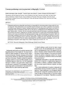
Fig 1 BaSO4 -based scan prosthesis used for the representation of the final prosthetic outcome in mucosally-supported guide and bone-supported guide groups. In order to facilitate the virtual planning of the implants, cylindric guidance holes corresponding to the axial center of the teeth were also prepared.
visualization of the available bone volume as well as the prosthetic outline, allowing the optimal implant position to be planned. However, a computer-aided method used in conjunction with stereolithographic (SLA) surgical guides is technically demanding, and there is little evidence of its benefit over the traditional method,5 particularly from the prosthetic point of view. The aim of this study was to compare the incidence of and confounding factors in implant positioning errors related to the use of freehand and computer-aided treatment methods. A clinical study in a single-blind design was conducted to test the following null hypothesis: The three types of implant placement methods (two different types of computer-aided implant placement methods and the freehand method entailing intuitive manual placement of fixtures to suitable crestal bone as described by Adell et al1 and Brånemark et al4) applied to the fixed-prosthetic rehabilitation of totally edentulous arches are not associated with a statistically significant difference regarding (1) the incidence of implant positioning error(s) and (2) related confounding factors.
MATERIALS AND METHODS This study was approved by the ethical committee of Istanbul University and conducted in accordance with the Helsinki declaration of 1975 as revised in 2000. The required sample size was estimated using a statistical package (Graphpad, Statmate, Graphpad Software) on the basis of a statistical significance level of P < .05 and power of 80%. Considering the failure rate of 3% and a dropout (or withdrawal of the consent) rate of 15% 2 Volume 28, Number 1, 2013
in a previous study,9 an estimated minimum of 300 implants (corresponding to an approximate number of 57 implant-supported, full-arch fixed prostheses) were calculated. Patients referred to the Department of Oral Implantology, Faculty of Dentistry, Istanbul University, between January 2007 and August 2009 with at least one edentulous arch; with healthy systemic and oral status; and without severe alveolar bone atrophy, major alveolar hard and/or soft tissue deficiency, mouth opening restriction, heavy smoking (> 10 cigarettes per day), and parafunctional habits were included in the study. All patients were initially evaluated for the suitability of an implant-supported fixed prosthesis and any patients unsuitable for such a prosthetic suprastructure (eg, orthognathic malocclusions, insufficient hygiene practice) were excluded. Fifty-four patients (31 women and 23 men) with a mean age of 52.5 years (range, 28 to 74 years) were included in the study. All patients were initially evaluated via panoramic radiographs and clinical examination. Patients were informed about the study, and written approval of participation was obtained from all subjects. Patients willing to be treated with the computeraided method (27 patients) were prepared for the procedure. A BaSO4-based scan prosthesis was produced to represent the final prosthetic outline for patients in the guided surgery group (Fig 1). For this purpose, mucosalevel impressions were obtained, and base templates were prepared for registration of the centric occlusion and vertical dimension, as with the methods used for fabrication of a complete denture. In accordance with these records, the laboratory technician prepared a tooth setup. This setup was checked in situ to obtain patient approval in terms of esthetic appearance, phonetics, incisal overjet, and overbite level. The amount of keratinized mucosa on the edentulous crest was also recorded via periodontal probe and intraoral photograph. Finally, the 27 patients selected (31 edentulous arches) were forwarded to cone beam computed tomography (CBCT) imaging (ILUMA, Imtec Imaging) with the scan prosthesis. Acquired data were transferred to a personal computer and initially investigated by examination software (Iluma Vision, Imtec Imaging). Patients with sufficient alveolar bone thickness (> 4 mm) and keratinized mucosa (> 4 mm in the buccal and lingual aspect of the edentulous crest) were identified (12 patients with 16 arches) and allocated for operation with mucosa-supported guides (SIM group). Fifteen patients (15 arches) showing possible need of augmentation for buccal dehiscence defects were allocated for operation with bone-supported guides (AYT group). The remaining 27 patients were allocated for operation with the freehand method (control group). The lack of incision and sutures involved in the use of mucosa-supported guides increased the motivation
Arısan et al
of patients in the SIM group. However, three patients allocated to the AYT group refused to participate and wanted operations with the standard method; these patients were therefore transferred to the control group. The final distribution of patients in the SIM, AYT, and control groups was 12, 12, and 27 (16, 12, and 33 arches), respectively.
Computer-Aided Planning and Guide Manufacturing
Segmentation of the jawbone and the scan prosthesis was performed by a trained technician, and the resulting data were uploaded to a dedicated software program used for the production of mucosa-supported (Simplant Planner, Materialise Dental) and bonesupported guides (Stent CAD, Media Lab). These software programs not only allowed exploration of the alveolar bone volume with reformatted axial and sagittal section windows, but they permitted the planning of a virtual implant in ideal relation with the threedimensional (3D) view of the scan prosthesis and available bone. In addition, the scan prosthesis, the implants, and the jawbone volume could be removed selectively from the 3D model. Taking advantage of these features, a total of 169 implants were planned, while attempting to achieve the best possible implant position. The software planning of the implants was performed by a clinician (VA) in accordance with the patient-specific considerations of the surgeons (VA, CK, and TÖ). A minimum of three fixation screws were also planned to prevent the mobility of the guide during osteotomy.9 The corresponding data were sent to production facilities, and 16 mucosa-supported (Simplant-SAFE, Materialise Dental) and 12 bonesupported SLA surgical guides (Classical Surgical Guide, Aytasarim) were obtained. All guides were manufactured according to the stereolithography principle. A single guide with changeable metal sleeves was used with the mucosa-supported guides in the SIM group, and a special drill kit, consisting of a mucotome, pilot, and twist drills was used for the osteotomy. Bonesupported guides used in the AYT group consisted of multiple guides incorporating metal tubes for each drill diameter; the osteotomy was performed with the standard set of drills from the implant manufacturer. The depth of the osteotomy was controlled by the surgeon in accordance with the level markings on the drills.
Implant surgery
Single guides in the SIM group were positioned over the mucosa, and local anesthesia was administered slowly through the osteotomy holes to avoid arbitrary dislocation of the guide due to injection-related mucosal swelling. Care was taken to establish the accurate guide position with the previously prepared occlusal
record, and the guide was fixed with 2-mm-diameter osteosynthesis screws. Following mucotomy and removal of the mucosa on the designated implant sockets, the osteotomies were completed using a special drill kit with predetermined length. Physical stoppers on the drills helped to control the osteotomy depth. Implants were inserted through the guides using a torque-controlled surgical motor and hand ratchet. Surgery was completed upon fastening of the gingival formers (Fig 2). In the AYT and control groups, a midcrestal incision (and vertically relieving incisions if needed) was performed on the edentulous crest, and a full-thickness flap was elevated. The bone-supported guides were seated over the alveolar bone. Care was taken to prevent any interference of the guide and the flap. Due to the need for replacement, the guides in the AYT group were not fixed but held firmly against the underlying alveolar bone by hand. The osteotomy was completed through the use of successive drills and corresponding guides. The level of the osteotomy was controlled visually and finally checked via depth gauge. The guide was removed, and the implants were inserted either by a torquecontrolled surgical motor or a hand ratchet (Fig 3). The surgery in the control group was accomplished in accordance with the freehand implant placement method as described by Adell et al1 and Brånemark et al.4 Selection of implant positions was determined according to prior planning on the panoramic radiograph and visual exploration of the edentulous alveolar crest. In the AYT and control groups the osteotomy was performed by the pilot, twist, and final osteotomy drills found in the surgical tray according to the written protocol of the implant system. The vertical position of the implants was aligned manually to be level with the marginal crestal level. Occasionally, the implants in the AYT and control groups were further screwed a half or one more round in order to embed the rough implant surface area into the thin crestal edge. Due to the occurrence of minor dehiscence defects, guided bone regeneration (GBR) procedure was applied around 25 implants (35%) in the AYT group and 68 implants (36%) in the control group. The length and diameter of the implants were between 8 to 14 mm and 3.4 to 4.5 mm, respectively. Gingival formers were fastened, and the flaps were re-positioned by interrupted silk sutures in the AYT and control groups. All implants were left to heal for 2 to 6 months, according to anatomical location or the application of GBR. In order to standardize the healing conditions between the three groups, all implants were left to transmucosal (one-stage) healing. The numbers of inserted implants in the SIM, AYT, and control groups were 97, 72, and 184, respectively. A total of 353 implants (182 SPI, Thommen Medical; The International Journal of Oral & Maxillofacial Implants 3
Arısan et al
Fig 2 Implant planning and surgery in the SIM (mucosally supported guide) group. (a) View of the planning software. The user can selectively eliminate the 3D models of bone, scan prosthesis, or implants out of the view by using the “disable” feature. (b) Single-type guides were provided with changeable metal sleeves, which control the orientation and depth of the osteotomy (asterisk). (c) Mucosa-supported guides were used with the special mucotome and drills, and the depth of the osteotomy was physically limited by the stops located in the ends of the drills (arrow).
a
*
b
171 Xive, Dentsply-Friadent) were placed by three surgeons (VA, CK, and TÖ), each with a minimum of 10 and 4 years of clinical experience in freehand and computer-assisted implant surgery techniques, respectively (Fig 4). All surgeons used the three techniques throughout the study. The allocation of implant brands was random in the study population; however, there was no combined use of both brands in the same patient. The number of implants placed per arch was between five and eight in all groups, and all implants were spread along the edentulous arch in the anterior-posterior direction so that cantilevers could be eliminated or kept to a minimum. The placement of all planned implants for each jaw was completed in one surgical session. Patients used soft-relined provisional prostheses, and they were instructed to refrain from eating hard foods during the healing period.
Prosthetic Work and Evaluation of Positioning Errors
Following the healing period, osseointegration was confirmed by radiologic and clinical examination. Following the impression stage, the laboratory cast was poured, and the prosthetic work was accomplished according to full-arch implant-supported prosthetic 4 Volume 28, Number 1, 2013
c
principles.4 The prosthetic work was performed by the same group of clinicians who placed the implants. In accordance with patient financial restrictions and esthetic demands, the vast majority of the prostheses were constructed in cemented design. Upon completion of the prosthetic work, all patients and their laboratory casts were forwarded to a blinded examiner (EM) trained in implant prosthetics. Prior to the initiation of the study, reliability and the consistency of the blinded examiner’s evaluation were calibrated by two nonparticipating patients, laboratory casts, and panaromic radiographs. All authors examined these patients and classified the implants according to the “positioning error” criteria described in Table 1. Then, the results were compared with each other and few inconsistent classifications were discussed and further clarified by setting the objective measures in order to reduce or eliminate examiner-related error. Unaware of which group any particular patient belonged to, the examiner evaluated all models and implants according to the “positioning error” criteria (Table 1). Panoramic radiographs obtained upon the delivery of the prostheses were included in the evaluation. The number of 15-degree and 25-degree angulated abutments was also recorded for comparison purposes (Fig 5).
Arısan et al
Fig 3 Planning and surgery in the AYT (bone-supported guide) group. (a) The position of the implants was planned with the help of the scan prosthesis and virtual axis lines on the 3D implant model (arrow). (b) Bone-supported guides consisted of multiple guides, including successive drill tubes prepared according to the implant system’s surgical drill diameters. (c) The direction of the osteotomy was controlled by the tubes in the guide, and the depth was aligned according to the markers on the drill (arrow).
a
b
c
Statistical Analysis
25
SIM AYT Control
Regular diameter Narrow diameter Wide diameter
20 15 10 5 No. of implants
The similarity of the number of implants placed per jaw in the groups was analyzed by the χ2 test. To avoid bias in the analysis of the multifactorial data pool, pair-wise comparisons were not undertaken. Initially, the differences of positioning errors between the three groups were analyzed by χ2 test to reveal any statistical significance. Then a logistic regression model was built in order to account for any clustering of positioning errors on the same implant and patient and to account for the effect of independent variables. The model was adjusted to the 13 confounding variables in Table 2. Backward elimination for the likelihood ratios method was used to fit the logistic regression, and insignificant variables were sequentially removed.10 The correspondence between the actual and predicted values of the dependent variable was investigated by a Hosmer and Lemeshow test.11 A goodness-of-fit statistic and Wald test were used to evaluate the significance of each coefficient when an acceptable model was found.12 Any P value below .05 was accepted as significant. Positioning errors described in Table 2 were consecutively analyzed in logistic regressions. Adjusted odds ratios (ORs) and corresponding 95% confidence intervals (CIs) were generated for all significant variables. Finally,
0
0
27 26 25 24 23 22 21 11 12 13 14 15 16 17 FDI tooth position 37 36 35 34 33 32 31 41 42 43 44 45 46 47
5 10 15 20 25
Fig 4 Distribution of regular-, narrow-, and wide-diameter implants in all groups.
The International Journal of Oral & Maxillofacial Implants 5
Arısan et al
Table 1
Implant Positioning Error Criteria Evaluated in the Study
Description
Method of evaluation
Definition of the expected ideal and the positioning error
Interproximal emergence
Oral examination and evaluation of the laboratory cast
The ideal emergence location of any implant was expected to be in the axis of the crown in a tooth-like form. An implant’s emergence coinciding with interproximal tooth area was defined as a positioning error.
Insufficient interimplant distance
Oral examination with a 2-mm diameter gauge and evaluation of the laboratory cast
For ease of hygiene and healthy maintenance of the surrounding tissues, a ≥ 2-mm distance was expected between any two neighboring implants. An implant’s smaller approximation was defined as a positioning error.
Improper parallelism
Oral examination and evaluation of the laboratory cast with a caliper
In the same segment, all implants were expected to be parallel and in the same axial direction. An implant’s 20-degree or more off-axial inclination (compared with neighboring implants) was defined as a positioning error.
Offset position
Oral examination and evaluation of the laboratory cast
The emergence point of any implant was expected to be on the top of the alveolar crest (midcrestal line), surrounded by the attached/keratinized mucosa (if available). An implant’s emergence from the vestibule or lingual/ palatal aspect of this zone was defined as a positioning error.
Excessive subcrestal placement
Panoramic radiograph and a transparent ruler
Implant shoulder platforms were expected to be at the level of the radiographically visible marginal alveolar crest. An implant’s 3-mm or deeper shoulder level on the panoramic radiograph was defined as a positioning error.
Implant-shoulder exposure
Oral examination
The whole body of the implant was expected to be not visible and completely surrounded by the bone and mucosa with no exposed margins in the shoulder area. An implant’s body exposure in the shoulder area was defined as a positioning error. (Exposure due to peri-implantitis was excluded).
Improper screw access hole
Visual examination of the screw-retained prosthesis
The access hole to the retention screw was expected to be on the occlusal surface of the molars and premolars and in the cingulum area of the incisors. An implant’s screw access hole outside the above-described area was defined as a positioning error.
*
a
b
c
d
e
f
Fig 5 Clinical examples of positioning errors examined in the study. (a) Esthetic compromise due to interproximal emergence of an implant was masked by pink porcelain (arrow). Visible metallic margin of the implant defined as “shoulder exposure” (asterisk). (b) Insufficient interproximal distance (arrow). (c) Improper parallelism of implants was compensated by the use of angulated abutments. The direction of the implant is opposing to the other implants in the same segment (arrow). (d) Excessive subcrestal placement of implant was detected on the panoramic radiograph (white line). The clinical crown of the corresponding implant was also elongated (arrow). (e) Offset positions of two implants in the mandible. The implants were surrounded by mobile mucosa (arrows). (f) Inappropriate screw access holes conforming to interdental palatal aspect of the screw-retained fixed prosthesis (arrows).
a model was used to predict the probability (%) of a positioning error of an implant in SIM, AYT, and control 6 Volume 28, Number 1, 2013
groups. All analyses were performed using a statistical software package (SPSS, IBM).
Arısan et al
Table 2
Variables Included in the Logistic Regression Analysis
Variable
Explanation
Treatment method
Mucosa-supported guide (SIM) Bone-supported guide (AYT) Freehand method (Control)
Surgeon
Surgeon I Surgeon II Surgeon III
Patient age
Continuous
Patient sex
Female Male
Opposing jaw restoration
No restorative work was performed/untreated. Simultaneously restored with opposing jaw.
Patient smoking status
Yes No
Implant type
Implants with 1-mm transmucosal polished collar (SPI Element) Implants without polished collar (Xive)
Implant length
Short length (8 mm) Regular length (9.5 and 11 mm) Long length (> 11m)
Implant diameter
Narrow diameter (3.4 and 3.5 mm) Regular diameter (3.8 and 4.0 mm) Wide diameter (4.5 mm and larger)
Region of the implant site
Anterior region (canine and incisor teeth) Posterior region (premolar and molars)
Anatomical location of the Implant
Maxilla Mandible
Number of implants in the jaw
5 6 7 8
GBR applied around the implant
Yes (applied) No (not applied)
RESULTS The number of implants placed per jaw was similar between SIM, AYT, and control groups (χ2= 2.216, P = .424). Eight implants (two in SIM, two in AYT, and four in control groups) failed prior to examination (five failures were due to postsurgery inflammation, and three were found loose [not osseointegrated] at the impression stage), yielding an overall 97.73% early-term survival rate. There were no implants in such a poor position such that it was not possible to take impressions or to fabricate prostheses for them. All implants were uneventfully restored via 58 metalceramic fixed restorations (16, 12, and 33 for SIM, AYT, and control groups, respectively) (Table 3). Three patients in the control group did not attend the positioning error examination, and the corresponding 19 implants (3 prostheses) were excluded. This resulted in the availability for analysis of clinical data from 326 implants supporting a total of 58 prostheses. The results of the
implants implants implants implants
Table 3 Distribution of Placed and Failed implants and of Prostheses Type SIM
AYT
Control
67 30 97
18 54 72
118 66 184
Implant failures before the loading stage Maxilla 0 1 Mandible 2 1
3 1
No. of placed implants Maxilla Mandible Total
No. of manufactured prostheses and their retention type Maxilla Cement retention 9 3 15 Screw retention 1 1 2 Mandible Cement retention Screw retention
5 1
7 1
11 2
Total Cement retention Screw retention
14 2
10 2
26 4
The International Journal of Oral & Maxillofacial Implants 7
Arısan et al
Table 4
Implant Positioning Errors Reported by the Blinded Examiner SIM
AYT
Control
Anatomical location
Accurate position
Positioning error
Accurate position
Positioning error
Accurate position
Positioning error
Interproximal emergence
Maxilla Mandible
63 26
4 2
12 47
5 6
74 55
19 10
Insufficient inter-implant distance
Maxilla Mandible
65 28
2 0
15 50
3 2
81 59
15 6
Improper parallelism
Maxilla Mandible
67 28
0 0
16 51
2 1
80 55
16 10
Offset position
Maxilla Mandible
64 21
2 8
14 45
3 8
91 59
5 6
Excessive subcrestal placement
Maxilla Mandible
64 27
3 1
17 51
1 1
90 60
6 5
Implant shoulder exposure
Maxilla Mandible
66 27
1 1
18 50
0 2
91 60
5 5
Improper screw access hole (out of 8 screwretained prostheses)
Maxilla Mandible
6 6
0 0
4 3
2 2
8 4
4 7
80 (84.21)
15 (15.78)
41 (58.57)
29 (41.42)
Evaluated criteria
Total no. of accurate and erroneous positioned implants (%)
positioning error examination according to the maxilla and mandible are presented in Table 4. Compared with the SIM group (5%), there were more implants emerging from the interproximal area in the AYT (16%) and control groups (19%), and the differences were statistically significant (χ2 = 11.77, P = .002). Implants placed via computer-aided methods showed a higher rate of success (98% and 93% for SIM and AYT groups, respectively) in maintaining a sufficient inter-implant distance compared with implants placed via the freehand method (control group, 77%; χ2 = 12.36, P = .002). In the SIM group, all implants were parallel (within 20 degrees) within the same segment, whereas 2% of implants in the AYT group and 16% of implants placed in the control group were not parallel to other implants positioned in the same segment, and the differences were statistically significant (χ2 = 23.34, P < .0001). In implants placed by computer-aided methods, there were more implants placed in an offset position (too lingual or buccal from the top of the alveolar crest, 11% and 13% for SIM and AYT groups, respectively) compared with the control group (7%) and the differences were statistically significant (χ2 = 6.243, P = .044, Figs 6a to 6d). Of the implants in SIM, AYT, and control groups, 4%, 6% and 7%, respectively, were placed excessively subcrestal, but the differences between the groups were not significant (Fig 6c). Shoulder exposure was detected in all groups (2%, 6%, and 5% for SIM, AYT, and control groups, respectively) but the differences were 8 Volume 28, Number 1, 2013
73 (45.34)
88 (54.65)
not statistically significant. Out of eight screw-retained prostheses, only two of the SIM group (12 implants) had proper screw access holes. Screw access holes in 36% and 48% of the implants in AYT and control groups, respectively, were improperly located, and the differences were statistically significant (χ2 = 8.301, P = .015, Fig 6g). When all implants were evaluated, whether having a positioning error or not, 55% of the implants in the control group were found to be mispositioned (erroneous), whereas 41% of implants in the AYT and 16% of implants in the SIM groups were mispositioned (erroneous), and the differences were statistically significant (χ2 = 37.49, P < .001, Fig 6h). The majority of implants were restored with straight abutments. Angulated abutments were used in 13% of implants in the SIM group and in 20% of implants in the AYT and control groups and there were no statistically significant differences among them (Fig 6i). It was also observed that implants in the control group were especially prevalent in premolars and molars. However, in the use of computeraided methods (SIM and AYT groups) the distribution of implants was rather more balanced and widespread along the alveolar arch (see Fig 4). Logistic regression analysis revealed that the use of the freehand method (OR = 2.828, 95% CI = 1.212 to 4.949, P < .0001), leaving the antagonist jaw untreated (OR = 1.214, 95% CI = 1.101 to 6.356, P = .001), placement in the posterior region (OR = 1.266, 95% CI = 1.12 to 2.256, P = .001), and application of GBR procedures around the implant (OR= 1.188, 95% CI = 1.102
Arısan et al
SIM 5 a
b
AYT
Control
16
95
84
2
7
98
93
19
100 11
d
89 4
e
96 2
f
98
13
100 16
h
16
96 13
2 11 i
87
84
Appropriate parallelism Implants with non-parallel position
χ2 = 23.34 df = 2 P < .0001
93
Appropriate midcrestal position Implants in offset position
χ2 = 6.243 df = 2 P = .044
Appropriate level Implants placed excessively subcrestal
NS
93
No implant-body exposure Implants with shoulder exposure
NS
95
52
Appropriate screw access hole Improper screw access hole
χ2 = 37.49 df = 2 P < .001
45
Implants in proper position Implants in erroneous position
χ2 = 37.49 df = 2 P < .001
Straight abutments 15-degree abutments 25-degree abutments
NS
7
87 6
7
94 6
5
94
48
64 41
84
55 59
5 15 80
χ2 = 11.77 df = 2 P = .002
Appropriate inter-implant distance χ2 = 12.36 Implants with insufficient inter-implant distance df = 2 P = .002
87
36 g
Appropriate tooth-axis emergence Implants emerging from the interproximal area
81
4 c
Statistics
4
16 80
Fig 6 Pie chart graphics and corresponding statistics of positioning errors in SIM, AYT, and control groups. (a) Interproximal emergence of implants. (b) Insufficient inter-implant distance. (c) Improper parallelism. (d) Offset position. (e) Excessive subcrestal placement. (f) Implant shoulder exposure. (g) Improper screw access hole (in screw-retained prosthesis). (h) Overall percentage of implants in proper and erroneous positions. (i) Straight and angulated abutments. NS= not statistically significant.
to 2.475, P = .001) were significantly associated with an interproximal emergence error (Table 5). Hence, the use of the freehand method (OR = 1.421, 95% CI = 1.212 to 1.946, P < .0001), female sex (OR = 0.312, 95% CI = 0.98 to 0.684, P = .001), posterior placement of implant (OR = 1.414, 95% CI = 1.216 to 3.684, P = .001), and simultaneous placement of eight implants (OR = 1.120, 95% CI = 1.086 to 3.445, P = .02) were significantly associated with an insufficient inter-implant distance error (Table 6). Also, the use of the freehand method (OR = 1.24, 95% CI = 1.032 to 3.220, P = .001), longlength implant (OR = 0.331, 95% CI = 0.306 to 0.967, P = .001), and simultaneous placement of eight implants (OR = 1.336, 95% CI = 1.046 to 6.210, P = .01) in the maxilla (OR = 0.256, 95% CI = 0.112 to 0.861,
P = .01) were significantly associated with an improper parallelism error (Table 7). The majority of implants were restored with straight abutments. Angled abutments were used in 13% of implants in the SIM group and in 20% of implants in the AYT and control groups, and there were no statistically significant differences among them (Fig 6i). When the logistic regression model was built while omitting the positioning error categories described in Table 1 with the following outcome variables: 1 = positioning error, 0 = no positioning error, the independent variables: surgeon, patient age, patient gender, opposing jaw’s restoration, patient smoking status, and implant type were found insignificant and removed, and the model shown in Fig 7 was found. The International Journal of Oral & Maxillofacial Implants 9
Arısan et al
Table 5 Variables in the Logistic Regression Model for Interproximal Emergence Error and Corresponding Wald Statistics β
Wald
df
P
Exp (β)
95% CI
Treatment method
Variable
Freehand method (control)
Explanation
1.223
13.140
1
.000
2.828
1.212 to 4.949
Opposing arch restoration
No restorative work performed/untreated
1.144
9.88
1
.001
1.214
1.101 to 6.356
Region of the implant
Posterior region
1.214
10.04
1
.001
1.266
1.12 to 2.256
GBR procedures
Yes (applied)
1.123
6.46
1
.001
1.188
1.102 to 2.475
β = estimate; Wald = Wald statistics; df = degrees of freedom; Exp (β) = odds ratio
Table 6 Variables in the Logistic Regression Model for Insufficient Inter-implant Distance Error and Corresponding Wald Statistics Explanation
(estimate)
Wald
df
P
Exp (β) (odds ratio)
95% CI
Freehand method (control)
1.284
16.45
1
.000
1.421
1.212 to 1.946
Variable Treatment method
β
Patient sex
Female
–0.163
4.28
1
.001
0.312
0.098 to 0.684
Region of the implant
Posterior region
1.313
8.42
1
.001
1.414
1.216 to 3.684
No. of implants in arch
8
1.208
3.41
1
.02
1.120
1.086 to 3.445
β = estimate; Wald = Wald statistics; df = degrees of freedom; Exp (β) = odds ratio
Table 7 Variables in the Logistic Regression Model for Improper Parallelism Error and Corresponding Wald Statistics Variable
β
Exp (β) (odds ratio)
Explanation
(estimate)
Wald
df
P
Treatment method
Freehand method (control)
1.336
21.72
1
.001
1.24
1.032 to 3.220
95% CI
Implant diameter
Long length
–0.331
4.66
1
.001
0.331
0.306 to 0.967
No. of implants in arch
8
1.202
2.67
1
.01
1.336
1.046 to 6.210
Anatomic location
Maxilla
–0.256
4.01
1
.01
0.256
0.112 to 0.861
β = estimate; Wald = Wald statistics; df = degrees of freedom; Exp (β) = odds ratio
According to this model, the positioning error probability of a regular-diameter and long-length implant placed by the freehand method in the control group in the posterior maxilla with a GBR procedure and within a group of eight implants is 88%. The positioning error probability of a wide-diameter and regular-length implant placed by bone-supported SLA guides in the AYT group in the posterior mandible with GBR procedure and within a group of six implants is 61%. Also, the positioning error probability of a narrow-diameter and long-length implant placed by mucosa-supported SLA guide in the SIM group in the anterior maxilla without GBR procedure and within a group of six implants is 6%. 10 Volume 28, Number 1, 2013
DISCUSSION The efficacy of two computer-aided implant placement methods for reducing implant-positioning error was evaluated and compared with the freehand method. The single-blind design of this study allows investigation of the final outcome and the relevant implant positioning errors, irrespective of awareness of placement method. The underlying reasons for such errors are multifactorial, and deployment of univariate as well as multivariate analysis permits objective discrimination of all possible associations. The use of logistic regression analyses permits observation of not only the
Arısan et al
Yˆ = –4.742 – 2423(treatment method) – 0.413(implant diameter) + 0.321(implant length) + 0.944(region of the implant) (0.421)
(0.842)
(0.820)
(0.622)
+ 1.214(anatomical location of the implant) + 1.123(GBR applied around implant) – 0.746(no. of implants in the jaw) (1.926)
(1.464)
(0.616)
Fig 7 Fitted logistic regression model for the probability of a positioning error. Numbers in parentheses represent the standard error.
significance of confounding factors,13 but also of the probability of a positioning error in the built model.14 The investigated positioning errors may cause a variety of compromised prosthetic, biomechanical, and peri-implant tissue complications that may seriously affect the longevity of an implant.15 Some of these errors may simply compromise peri-implant health or may even obscure the prosthetic restoration of already osseointegrated implants.16,17 The severity of the positioning errors may eventually leave no alternative other than removal of the osseointegrated implant.18 All these undesirable events represent lost time, effort, and resources that negatively affect patient cooperation and satisfaction. Computer-aided implant planning and placement methods, in conjunction with modern radiographic techniques, were developed to overcome such negative circumstances.5 Although positive results have been demonstrated using these techniques, the reported scientific data have focused mainly on implant and prosthetic success.19,20 To our knowledge, the present study is the first to compare the occurrence of such positioning errors with the use of computer-aided and freehand implant placement methods. The high levels of clinician experience in this study resulted in no nonrestorable implants or jaws. However, involvement of inexperienced surgeons may cause such negative outcomes as a result of implant mispositioning.21 Hence, for most of the evaluated criteria, positioning errors were more common in implants placed by the freehand method (control group). Interproximal emergence of implants may complicate daily hygiene procedures.22 In addition, achieving an esthetically appealing prosthetic result can be challenging, especially in the anterior maxilla.23 Compared with the SIM group (5%), this type of error was more frequent in the AYT (16%) and control groups (19%), and the differences were statistically significant. The logistic regression model also revealed that the interproximal emergence probability of an implant was associated with the use of the freehand method, placement in the posterior region, using GBR procedures, and leaving the
antagonist jaw untreated. It is quite likely that one or more implants would coincide with interproximal tooth area when crowded implant groups are simultaneously placed in the posterior region of the edentulous arch. The present results show that computer-aided planning and placement methods, in conjunction with singletype SLA mucosa-supported guides, are effective in the alleviation of this error. Implants that are too close together also tend to preclude optimal hygiene and maintenance; thus, the placement of implants should provide sufficient interimplant distance.24,25 Additionally, this is one of the vital prerequisites in establishing papilla formation.26 In a clinical study by Tarnow et al,27 a minimum distance of 3 mm was recommended between implants to provide adequate biologic conditions for papilla formation. The measurement of inter-implant distance was performed on laboratory casts, and a minimum 2-mm threshold was set because the prosthetic allowance is technically impaired below this distance; in addition papilla formation was not investigated in this study. Of the implants in the control group, 13% were too close together, whereas 2% and 7% of implants in the SIM and AYT groups, respectively, were identified as having this type of positioning error. The use of the freehand method in female patients for the placement of eight implants in the posterior region was significantly associated with excessive approximation of implants in the logistic regression analysis. The reason for this outcome may be due to the smaller alveolar arch in the female anatomy,28 which may further compromise the establishment of sufficient distance between implants, especially when eight implants are simultaneously inserted. In a systematic review by Renvert et al29 the prevention of this error was claimed to be very important, such that in untreatable situations the only option would be to leave the implant submerged and out of function. Clinically, the stressbearing service of any implant should be beneficial in all cases,30 and it can be concluded that computer-aided planning and placement of implants allows better control in sustaining sufficient distance between implants. The International Journal of Oral & Maxillofacial Implants 11
Arısan et al
Parallel placement of implants is a desired objective that, if not achieved, may render prosthodontic treatment more complex.31 Load-transfer conditions may also be compromised.32 The parallelism of implants was well established in the SIM and AYT groups, whereas 16% of implants in the control group were not parallel to neighboring implants in the same segment, and the differences between the groups were statistically significant. The logistic regression model revealed that the simultaneous placement of eight implants in the maxilla using the freehand method was significantly associated with this type of positioning error. Based on these results, it can be concluded that the use of computer-aided methods is indeed effective in establishing the parallelism of multiple implants, whereas the use of the freehand method is more likely to fail to achieve the parallelism of placed implants. The only shortcoming related to the use of the computer-aided method in the present study was in the establishment of a midcrestal emergence point. In the SIM and AYT groups, 11% and 13% of implants, respectively, were in offset position (emerging from a rather buccal or lingual aspect of the edentulous crest) and concomitantly surrounded by mobile mucosa. An experimental study on monkeys by Warrer et al33 demonstrated that the absence of keratinized mucosa around implants increased the susceptibility to plaque-induced bone loss. Recent evidence34 and clinical experience35 favor encircling of the available keratinized mucosa around the implant when possible. Appropriate midcrestal positioning and emergence of the implant is essential to achieving this goal. In the present study, the rate of offset-positioned implants was lower in the control group (7%), and the differences between groups were significant. However, no significant associations were found in the logistic regression analysis (probably due to the low number of mispositions). Although the CBCT images provided detailed information regarding hard tissues, the exact midcrestal tip was detectable neither in reformatted CBCT sections nor in three-dimensional virtual models. The implants were planned in accordance with the visible radio-opaque objects: bone and the scan prostheses (see Figs 2a and 3a). Due to uncertainty of the clinical midcrestal tip point and the borders of the attached mucosa resulting from their invisibility in the software display, the planned implant emergence point occasionally was “out-of-target” in the SIM and AYT groups (Fig 5e). This was especially obvious in the anterior mandible, where the resorption patterns are somewhat inconsistent.36 The risk of peri-implantitis and esthetic failure are more likely with this type of positioning error37 and could probably be addressed via improvements in the production of the scan prosthesis. The removal of attached mucosa with the mu12 Volume 28, Number 1, 2013
cotomes would be another contributing factor in any appraisal of this undesired outcome.38 Excessive subcrestal placement of the implant body into alveolar bone may complicate uncovering (stage two surgery), impression, and prosthetic procedures following the osseointegration stage.39 The crown-toimplant ratio also increases. Additionally, the risk from unnoticed excess cement may arise when the implantabutment prosthetic margin (and micro gap) is located deep below the gingival margin.40 This error occurred in all groups at a rate between 4% and 7%, and no statistically significant differences were found between them. When the affected implants of the SIM and AYT groups were evaluated, it was noticed that, during the software planning the shoulder level of implants was shifted slightly to the apical in order to reduce the risk of a dehiscence defect. This concern was prominent in areas where the clarity of CBCT images was not sufficiently sharp, especially in the coronal aspect. Hence, in the control group, these implants were intentionally screwed one more turn to achieve improved bone coverage. Small and Tarnow41 demonstrated that the occurrence of gingival recession and subsequent exposure of the implant metallic components were common following open-flap implant surgery. Recession may occur as a result of progressive marginal bone loss and may be an indicator of peri-implantitis.42 One clinical study following 44 patients and 76 implants showed that flapless implant surgery may be advantageous for preserving peri-implant mucosal form.43 Nevertheless, unfavorable positioning of the implant body far buccally from the alveolar crest would inevitably lead to soft tissue recession and shoulder exposure.44 Shoulder exposure was not frequent but was detected in all groups at a rate between 2% and 6%, and the differences were not statistically significant. Radiographic examination of affected implants revealed no significant bone resorption, excluding bone loss as a possible cause of this condition. The majority of these implants in the control group were applied with GBR procedure, and GBR was previously reported as a causative factor for gingival recession and shoulder exposure.45,46 In the SIM and AYT groups, however, there were no causes attributable for shoulder exposure, except deviation errors associated with the use of SLA guides.9,47 The use of either submerged or supracrestal collar (1-mm machined) implants showed no statistically significant difference or association in the logistic regression analysis. Alternate use of less invasive methods in the treatment of peri-implant dehiscence defects should be tested for alleviation of the occurrence of implant shoulder exposure.48,49 Unfavorable location of a screw access hole may seriously jeopardize the final esthetic appearance of the
Arısan et al
prosthesis, especially if it corresponds to the buccal aspect.50 In a clinical study by De Boever et al,51 screwretained prostheses showed nearly twice as many complications (57%) as cemented ones, and improper screw access holes was one of the negative factors discussed. There were no improper screw access holes in the SIM group, whereas 36% and 48% of the implants in the AYT and control groups, respectively, corresponded to unfavorable screw access holes on the prostheses they were supporting; the differences were also statistically significant. An insufficient number of screw-retained prostheses in this study (n = 8) precludes reaching any conclusion. However, the method used in the SIM group seems effective in aligning ideal screw access holes congruent with the supporting implants. A larger group of implants and screw-retained prostheses must be investigated to reveal whether the use of computeraided methods provides additional benefits in preventing this type of implant positioning error. The use of angulated abutments is common in the restoration of edentulous jaws, but load-transfer conditions in the use of such abutments were shown to be compromising.52 Overall cost of the treatment would also increase in parallel with the use of angulated abutments. In the present study, the number of angulated abutments was due to the preference of the dental technician during the laboratory stage. Although the use of angulated abutments was higher in the control group (20%), there were no statistically significant differences between the groups, and the use of angulated abutments may not be correlated with any of the methods described in this study. The differences in erroneous implants were significant between the groups, and the SIM group showed the lowest proportion of implants with errors (16%). A logistic regression model revealed a high positioning error probability (88%) in the use of the freehand method, when a group of eight implants were placed in the posterior maxilla in conjunction with a GBR procedure. The association of regular-diameter and longlength implants was due to the accumulated use of these implants in the posterior maxilla (see Fig 4), and the frequent use of GBR around these implants was due to the patient selection criteria. It comes as no surprise that freehand placement of such a high number of implants in the visually restricted posterior maxilla may have exhibited any of the positioning errors. However, computer-aided implant placement methods, especially those used for the placement of implants in the SIM group, showed a very low probability of error (6%) for implants placed in the anterior maxilla. The association of implant diameter and length was due to preferred use of such dimensions in the anterior maxilla, and naturally, GBR was not involved in flapless surgeries.
In contrast to the SIM group, a model revealing a relatively high error probability (61%) for implants placed in the posterior mandible was found in the AYT group. This could be due to patient selection criteria selectively allocating the relatively “easy” group of patients (sufficient bone volume) to the mucosa-supported guides (SIM group). The patient selection criteria used were mandatory for performing a flapless surgery. As a result, the placement of implants in the AYT and control groups was rather more complicated and was occasionally associated with GBR procedures. Another important pitfall specific to the AYT group could be deviations related to in situ movement of bone-supported guides, especially during osteotomy of posterior implant recipient sites.9,47 Due to multiple-type use of these guides, no fixation was provided other than holding firmly by hand, and this complicated the surgery: The drills occasionally slid over the thin alveolar crest, and the guide simply moved. These conditions might have introduced additional deviations between the planned and placed implants.9,47,53 Another contributing factor would be the enhanced viewing and planning capabilities of the software used in the SIM group, which made it possible to evaluate bone anatomy, realistic implants, and scan prostheses independently or in combination (see Fig 2a). These conditions may have a significant influence on the erroneous positioning of implants, especially in the posterior mandible, which is further complicated by patients’ mouth-opening limit. Therefore, the results of this study must be interpreted accounting the patient selection criteria; selectively allocating patients with limited bone width to AYT and control groups and patients with abundant bone and keratinized mucosa to the SIM group. Nevertheless, this selection process was not specific for the present study and is the protocol to be complied with for the adoption of computer-aided implant placement techniques in the clinical environment. It should also be emphasized that the freehand implant placement in the control group caused a complete uncertainty and lack of information regarding the implant-prosthesis relation, which led the surgeons to place the implants where the bone volume appeared the most abundant. The outcome might have been better if surgeries in the control group were performed by any means of another surgical guidance appliance (other than an SLA guide) such as vacuumformed plates54 or acrylic stents with embedded radiopaque markers.53 One of the noteworthy findings from the control group was the accumulation of implants in the premolar and molar areas. There were two main reasons why surgeons preferred this location. First, the appropriate bone height and width was more frequently encountered in the canine and premolar areas than The International Journal of Oral & Maxillofacial Implants 13
Arısan et al
in the incisor or molar areas. Secondly, the complications related to unfavorably positioned implants in the anterior maxilla could be severe, especially if the patient has a high smile line and the implant is not in the “perfect” position.41 The distribution of implants in the SIM and AYT groups was relatively more “balanced” compared with the control group. Clearly, this was a result of CBCT imaging and 3D software planning. In the control group, however, the planning of the implants was spontaneous and based on the intuitive decisions of the surgeon with respect to the limited information derived from the panoramic radiograph and visible bone morphology. Accurate assessment of the potential implant recipient area is also complicated by irregular resorption patterns in the anterior area.55 In this study, the placement and restoration of implants and prostheses were performed by the same clinicians. These phases are often performed by different clinicians. The surgeon would prefer to position the implant in the most biologically favorable position; the restorative dentist, however, requires implant placement that complies with the most esthetically and functionally appealing prosthetic position. For the permanent restoration to be successful, a complementary combination of both approaches must be achieved. Another benefit of implementing computeraided implant planning would be increased communication in terms of the implant–prosthesis relationship among clinicians placing and restoring the implants. Despite the demonstrated benefits, the adoption of this method demands an investment of significant resources and time for complete comprehension of the technology. Accordingly, the utilization of computeraided methods in any treatment plan must be justified with respect to their benefits and cost-effectiveness. Within the selection criteria and limits of this study, it can be concluded that erroneous placement of implants occurs frequently with freehand techniques and that utilization of computer-aided implant placement methods may alleviate such errors in edentulous jaws considered for fixed restoration. The use of software allowing selective elimination of scan prosthesis, bone, and implant prosthetic spaces, in conjunction with screw-retained, single-type, mucosa-supported SLA guides, further reduces such errors. Improvements in the field of scan prosthesis design should address prevention of offset implant positioning.
ACKNOWLEDGMENTS The authors thank Dr Sevda Özel of the Department of Biostatistics, Faculty of Medicine, Istanbul University for performing the statistical analysis in this study. Dr Nuriye Ertan Açıkgöz from Veritas Data Analysis Ltd, Istanbul is also acknowledged for as-
14 Volume 28, Number 1, 2013
sisting the data entry. All authors are full-time academic staff and declare no conflict of interest with respect to any brand, device, or entity mentioned in this study. This study was partly sponsored by Istanbul University Research Fund (Project no: 15111), Risus Medical (Turkish Branch of Thommen Medical, SPI, Waldenburg, Switzerland), and Dentsply-Friadent, Istanbul, Turkey.
REFERENCES 1. Adell R, Eriksson B, Lekholm U, Branemark PI, Jemt T. Long-term follow-up study of osseointegrated implants in the treatment of totally edentulous jaws. Int J Oral Maxillofac Implants 1990;5:347–359. 2. Romeo E, Chiapasco M, Ghisolfi M, Vogel G. Long-term clinical effectiveness of oral implants in the treatment of partial edentulism. Seven-year life table analysis of a prospective study with ITI dental implants system used for single-tooth restorations. Clin Oral Implants Res 2002;13:133–143. 3. Naert I, Koutsikakis G, Duyck J, Quirynen M, Jacobs R, van Steenberghe D. Biologic outcome of implant-supported restorations in the treatment of partial edentulism. Part I: A longitudinal clinical evaluation. Clin Oral Implants Res 2002;13:381–389. 4. Zarb GA, Jansson T. Prosthodontic Procedures. In: Branemark PI , Zarb GA, Albrektsson T (eds). Tissue-Integrated Prosthesis: Osseointegration in Clinical Dentistry. Chicago: Quintessence,1985:241–282. 5. Rosenfeld AL, Mandelaris GA, Tardieu PB. Prosthetically directed implant placement using computer software to ensure precise placement and predictable prosthetic outcomes. Part 1: Diagnostics, imaging, and collaborative accountability. Int J Periodontics Restorative Dent 2006;26:215–221. 6. Basten CH. The use of radiopaque templates for predictable implant placement. Quintessence Int 1995;26:609–612. 7. Arisan V, Karabuda CZ, Ozdemir T. Implant surgery using bone- and mucosa-supported stereolithographic guides in totally edentulous jaws: Surgical and post-operative outcomes of computer-aided vs. standard techniques. Clin Oral Implants Res 2010;21:980–988. 8. Sarment DP, Al-Shammari K, Kazor CE. Stereolithographic surgical templates for placement of dental implants in complex cases. Int J Periodontics Restorative Dent 2003;23:287–295. 9. Arisan V, Karabuda ZC, Ozdemir T. Accuracy of two stereolithographic guide systems for computer-aided implant placement: A computed tomography-based clinical comparative study. J Periodontol 2010; 81:43–51. 10. Hosmer DW, Jr., Wang CY, Lin IC, Lemeshow S. A computer program for stepwise logistic regression using maximum likelihood estimation. Comput Programs Biomed 1978;8:121–134. 11. Hosmer DW, Hjort NL. Goodness-of-fit processes for logistic regression: Simulation results. Stat Med 2002;21:2723–2738. 12. Lemeshow S, Hosmer DW, Jr. Estimating odds ratios with categorically scaled covariates in multiple logistic regression analysis. Am J Epidemiol 1984;119:147–151. 13. Blizzard L, Hosmer DW. The log multinomial regression model for nominal outcomes with more than two attributes. Biom J 2007;49:889–902. 14. Blizzard L, Hosmer DW. Parameter estimation and goodness-of-fit in log binomial regression. Biom J 2006;48:5–22. 15. Berglundh T, Persson L, Klinge B. A systematic review of the incidence of biological and technical complications in implant dentistry reported in prospective longitudinal studies of at least 5 years. J Clin Periodontol 2002;29(Suppl 3):197-212, discussion 232–193. 16. Raghoebar GM, Visser A, Vissink A. Correction of a malpositioned endosseous implant by a segmental osteotomy: A case report. Int J Oral Maxillofac Implants 2005;20:627–631. 17. Zechner W, Bernhart T, Zauza K, Celar A, Watzek G. Multidimensional osteodistraction for correction of implant malposition in edentulous segments. Clin Oral Implants Res 2001;12:531–538. 18. Stacchi C, Costantinides F, Biasotto M, Di Lenarda R. Relocation of a malpositioned maxillary implant with piezoelectric osteotomies: a case report. Int J Periodontics Restorative Dent 2008;28:489-495. 19. Di Giacomo GA, Cury PR, de Araujo NS, Sendyk WR, Sendyk CL. Clinical application of stereolithographic surgical guides for implant placement: preliminary results. J Periodontol 2005;76:503-507.
Arısan et al
20. Fortin T, Bosson JL, Coudert JL, Isidori M. Reliability of preoperative planning of an image-guided system for oral implant placement based on 3-dimensional images: An in vivo study. Int J Oral Maxillofac Implants 2003;18:886–893. 21. Van de Velde T, Glor F, De Bruyn H. A model study on flapless implant placement by clinicians with a different experience level in implant surgery. Clin Oral Implants Res 2008;19:66–72. 22. Wolff L, Kim A, Nunn M, Bakdash B, Hinrichs J. Effectiveness of a sonic toothbrush in maintenance of dental implants. A prospective study. J Clin Periodontol 1998;25:821–828. 23. Stanford CM. Achieving and maintaining predictable implant esthetics through the maintenance of bone around dental implants. Compend Contin Educ Dent 2002;23:13–20. 24. Heitz-Mayfield LJ. Peri-implant diseases: Diagnosis and risk indicators. J Clin Periodontol 2008;35:292–304. 25. Ferreira SD, Silva GL, Cortelli JR, Costa JE, Costa FO. Prevalence and risk variables for peri-implant disease in Brazilian subjects. J Clin Periodontol 2006;33:929–935. 26. Zetu L, Wang HL. Management of inter-dental/inter-implant papilla. J Clin Periodontol 2005;32:831–839. 27. Tarnow DP, Cho SC, Wallace SS. The effect of inter-implant distance on the height of inter-implant bone crest. J Periodontol 2000;71:546–549. 28. Lindsten R. Secular changes in tooth size and dental arch dimensions in the mixed dentition. Swed Dent J Suppl 2003;157;:1–89. 29. Renvert S, Roos-Jansaker AM, Claffey N. Non-surgical treatment of peri-implant mucositis and peri-implantitis: A literature review. J Clin Periodontol 2008;35:305–315. 30. Roos-Jansaker AM, Lindahl C, Renvert H, Renvert S. Nine- to fourteen-year follow-up of implant treatment. Part I: Implant loss and associations to various factors. J Clin Periodontol 2006;33:283–289. 31. Spielman HP. Influence of the implant position on the aesthetics of the restoration. Pract Periodontics Aesthet Dent 1996;8:897–904, quiz 906. 32. Satoh T, Maeda Y, Komiyama Y. Biomechanical rationale for intentionally inclined implants in the posterior mandible using 3D finite element analysis. Int J Oral Maxillofac Implants 2005;20:533–39. 33. Warrer K, Buser D, Lang NP, Karring T. Plaque-induced peri-implantitis in the presence or absence of keratinized mucosa. An experimental study in monkeys. Clin Oral Implants Res 1995;6:131–138. 34. Chung DM, Oh TJ, Shotwell JL, Misch CE, Wang HL. Significance of keratinized mucosa in maintenance of dental implants with different surfaces. J Periodontol 2006;77:1410–1420. 35. Martin W, Lewis E, Nicol A. Local risk factors for implant therapy. Int J Oral Maxillofac Implants 2009;24 (Suppl):28–38. 36. Albandar JM, Rise J, Gjermo P, Johansen JR. Radiographic quantification of alveolar bone level changes. A 2-year longitudinal study in man. J Clin Periodontol 1986;13:195–200. 37. Lindhe J, Meyle J, Group DoEWoP. Peri-implant diseases: Consensus Report of the Sixth European Workshop on Periodontology. J Clin Periodontol 2008;35:282–285. 38. Artzi Z, Tal H, Moses O, Kozlovsky A. Mucosal considerations for osseointegrated implants. J Prosthet Dent 1993;70:427–432. 39. Hammerle CH, Bragger U, Burgin W, Lang NP. The effect of subcrestal placement of the polished surface of ITI implants on marginal soft and hard tissues. Clin Oral Implants Res 1996;7:111–119.
40. Thomas GW. The positive relationship between excess cement and peri-implant disease: A prospective clinical endoscopic study. J Periodontol 2009;80:1388–1392. 41. Small PN, Tarnow DP. Gingival recession around implants: A 1-year longitudinal prospective study. Int J Oral Maxillofac Implants 2000; 15:527–532. 42. Kotsovilis S, Karoussis IK, Trianti M, Fourmousis I. Therapy of periimplantitis: A systematic review. J Clin Periodontol 2008;35:621–629. 43. Lee DH, Choi BH, Jeong SM, Xuan F, Kim HR. Effects of flapless implant surgery on soft tissue profiles: A prospective clinical study. Clin Implant Dent Relat Res 2011;13:324–329. 44. Fransson C, Wennstrom J, Tomasi C, Berglundh T. Extent of peri-implantitis-associated bone loss. J Clin Periodontol 2009;36:357–363. 45. Buser D, Bornstein MM, Weber HP, Grutter L, Schmid B, Belser UC. Early implant placement with simultaneous guided bone regeneration following single-tooth extraction in the esthetic zone: A crosssectional, retrospective study in 45 subjects with a 2- to 4-year follow-up. J Periodontol 2008;79:1773–1781. 46. Van der Zee E, Oosterveld P, Van Waas MA. Effect of GBR and fixture installation on gingiva and bone levels at adjacent teeth. Clin Oral Implants Res 2004;15:62–65. 47. Vercruyssen M, Jacobs R, Van Assche N, van Steenberghe D. The use of CT scan based planning for oral rehabilitation by means of implants and its transfer to the surgical field: A critical review on accuracy. J Oral Rehabil 2008;35:454–474. 48. Arisan V, Ozdemir T, Anil A, Jansen JA, Ozer K. Injectable calcium phosphate cement as a bone-graft material around peri-implant dehiscence defects: A dog study. Int J Oral Maxillofac Implants 2008;23:1053–1062. 49. Jeong SM, Choi BH, Li J, Xuan F. Simultaneous flapless implant placement and peri-implant defect correction: An experimental pilot study in dogs. J Periodontol 2008;79:876–880. 50. Hebel KS, Gajjar RC. Cement-retained versus screw-retained implant restorations: Achieving optimal occlusion and esthetics in implant dentistry. J Prosthet Dent 1997;77:28–35. 51. De Boever AL, Keersmaekers K, Vanmaele G, Kerschbaum T, Theuniers G, De Boever JA. Prosthetic complications in fixed endosseous implant-borne reconstructions after an observations period of at least 40 months. J Oral Rehabil 2006;33:833–839. 52. Kao HC, Gung YW, Chung TF, Hsu ML. The influence of abutment angulation on micromotion level for immediately loaded dental implants: A 3-D finite element analysis. Int J Oral Maxillofac Implants 2008;23:623–630. 53. Atsu SS. A surgical guide for dental implant placement in edentulous posterior regions. J Prosthet Dent 2006;96:129–133. 54. Akca K, Iplikcioglu H, Cehreli MC. A surgical guide for accurate mesiodistal paralleling of implants in the posterior edentulous mandible. J Prosthet Dent 2002;87:233–235. 55. Mecall RA, Rosenfeld AL. Influence of residual ridge resorption patterns on fixture placement and tooth position, Part III: Presurgical assessment of ridge augmentation requirements. Int J Periodontics Restorative Dent 1996;16:322–337.
The International Journal of Oral & Maxillofacial Implants 15