layer protocols is given, network performance metrics and our experimental setup .... ing system was Ubuntu 10.04 LTS running the default ker- nel. The USRP2 ...
Implementation and Evaluation of a Practical SDR Testbed André Puschmann, Mohamed A. Kalil, Andreas Mitschele-Thiel Integrated Communication Systems Group Ilmenau University of Technology P.O. Box 100 565, 98684 Ilmenau, Germany
{andre.puschmann,mohamed.abdrabou,mitsch}@tu-ilmenau.de ABSTRACT Software defined radios provide a perfect playground for researchers to experiment with current and future wireless communication systems. However, the benefits, especially for communication protocols, largely depend on non-functional requirements (i.e. temporal behavior) that have to be met by the system architecture. In this paper, we share our experience with a flexible SDR framework named Iris. We present an implementation of a Send-and-Wait Automatic Repeat reQuest (ARQ) protocol as well as a virtual network driver component which, in conjunction with Iris, form the core of our software defined radio networking testbed. To verify the practical suitability of the testbed and to evaluate the performance of the protocol, we are conducting end-toend throughput and delay benchmarks.
Categories and Subject Descriptors C.2.1 [Computer-Communication Networks]: Network Architecture and Design—Wireless communication
General Terms Design, Experimentation, Measurement, Performance, Verification
Keywords Cognitive Radio; Software radio; USRP2; Iris; benchmark; latency
1. INTRODUCTION Software Defined Radio (SDR) has created new opportunities for designing and implementing future wireless communication systems. In order to maximize flexibility, the main functionality of a radio transceiver is implemented and controlled by software. This enables a SDR to operate in multiple frequency bands using multiple transmission protocols. The drawback, however, is that software usually runs
Permission to make digital or hard copies of all or part of this work for personal or classroom use is granted without fee provided that copies are not made or distributed for profit or commercial advantage and that copies bear this notice and the full citation on the first page. To copy otherwise, to republish, to post on servers or to redistribute to lists, requires prior specific permission and/or a fee. CogART ’11, October 26 - 29 2011, Barcelona, Spain Copyright 2011 ACM 978-1-4503-0912-7/11/10 ...$10.00.
slower than hardware implementations. Layer 2 (data link layer) protocols, have temporal requirements that have to be ensured by the system architecture to guarantee correct operation. They not only need to schedule certain actions highly accurate and in a cyclic manner (i.e. TDMA-based protocols), but also need to react within a bounded, relatively short amount of time on certain stimuli (i.e. ACK packets or back-off times in CSMA-based protocols). Therefore, with regard to the communication, it is important to understand the characteristics and the performance, i.e. the processing delay, of the complete SDR architecture. In this paper, we describe a practical SDR networking testbed which has been developed on the basis of Iris [4]. It comprises a Send-and-Wait ARQ protocol and uses a virtual network adapter to connect to the networking stack of the operating system. Using this testbed, we conduct throughput and delay benchmarks, study the processing delay on packet-granularity and investigate the impact of Layer 2 error control mechanisms on higher layer transport protocols. Furthermore, we investigate the impact of the receive buffer size of the SDR on the communication latency and jitter. The obtained results are useful for protocol designers and system engineers. In particular, they help to mark down the performance of purely software defined radio communication systems using the USRP2 device. The rest of the paper is organized as follows. Section 2 discusses related work. The following section gives an overview about the software components and devices used in our work. Moreover, a short introduction to data link layer protocols is given, network performance metrics and our experimental setup are described. Section 4 explains implementation details of the software used for experimentation. In section 5 we present and discuss the results of the performance evaluation. Finally, we conclude this paper with an outlook on future activities in section 6.
2. RELATED WORK In the recent past, a number of research projects in the field of SDR networking have been presented. In [7], Li et al. developed a SDR networking platform using GNU Radio and the USRP. They integrated a Tun/Tap device into their solution and additionally studied the impact of channel quality and different modulation schemes. In [1], based on their previous observations, Nychis et al. developed a splitfunctionality approach in order to overcome the communication delays introduced through SDR and the USRP. Moving time sensitive functionality closer to the radio promises better performance in terms of delay. The drawback, however,
is the decreased flexibility and higher implementation complexity. The communication delay of the USRP1 and the increased delay in SDRs in general have been examined by Schmid et al. [6] and Valentin et al. [3]. In [2], O’Sullivan et al. employ a multi-hop Aloha using the SDR framework Iris and the USRP1 as RF-frontend. To the best knowledge of the authors, this is the first work which employs the USRP2 device for Layer 2 protocol development.
3. BASICS 3.1 USRP and UHD A common SDR comprises two main building blocks: a host component featuring a General Purpose Processor (GPP) responsible for signal processing and a RF front-end connected to the host, which itself receives and transmits base-band modulated signals. The Universal Software Radio Peripheral (USRP) and its successor, the USRP2, are often chosen to implement the RF part in SDR solutions in both academic and commercial systems. The main reasons for this are the comparatively low price, the wide functional range as well as the good community support. The Universal Hardware Driver (UHD) is a novel user space driver library for the USRP product family and possibly other RF frontends.
3.2 Iris Iris [4] is a highly reconfigurable framework for constructing component-based software radios and has been developed at the University of Dublin, Trinity College, Ireland. It is implemented as a user-space C++ application and allows to pass a radio configuration file as a command-line parameter. This XML-formatted file contains all components of the radio, defines their parameters and describes the connections between them. Network stack support as well as the built-in capability for triggering events and sending messages between components are unique features of Iris when compared to other SDR frameworks (i.e. GNU Radio).
3.3 Send-and-Wait ARQ Send-and-Wait, also known as Stop-And-Wait [5], is an Automatic Repeat Request (ARQ) protocol and has been used in this work to evaluate the SDR performance in a practical environment. This basic data link protocol ensures that data packets are reliably transmitted between two nodes. It allows only one pending packet and waits until it receives the acknowledgement (ACK packet) before advancing to the next packet. In case the sender doesn’t receive the correct ACK within a specified amount of time (ACK timeout), it retransmits the packet and again waits for it to be acknowledged. Send-and-Wait in its basic version only allows low network utilization. Improvements, such as GoBack-N, have been developed that increase the throughput by pipelining consecutive packets.
3.4 Performance metrics We evaluate the performance of our networking testbed using two fundamental metrics: throughput and delay. In communication systems, throughput is the amount of data that can be transferred from one node to another within a given amount of time. Using a Send-and-Wait ARQ protocol, the throughput (T PSW ) of a system may be calculated
at the sender by transmitting a single packet and measuring the time that elapses between transmission of the packet and reception of the acknowledgement. This time is also known as the round-trip-time (RTT) of a packet. The throughput equals the packet size divided by the measured time and can be given as follows: T PSW = packetsize/RT TL2
(1)
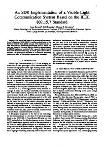
Here, the RTT is only measured inside the protocol (denoted as RT TL2 ). Therefore, it includes the request packet (which holds the payload, i.e. ICMP request) and the corresponding Layer 2 acknowledgement (without any additional payload). The RTT could also be measured at application level, i.e. using the ping command (denoted as RT Tping ). Figure 1 depicts the relationship between the RTT of a packet measured at Layer 2 and measured at application level. It shows the packets being sent between two nodes (N1, N2) over a certain period of time. Note that this protocol uses explicit acknowledgements like conventional IEEE 802.11 networks. This is why in the latter case, three packets are needed in total to complete one cycle (the width of the parallelogram indicates the size of the packet). Disabling ACK packets at Layer 2 (unacknowledged mode) leads to a symmetrical system setup (see Figure 2). Therefore, the RTT comprises twice the delay between sender and receiver because only two (equally large) packets are needed to complete one round trip. RT Tping = 2 · (Ttrans + Tproc )
(2)
RTT is an important measure and affects the range of crucial protocol parameters like inter frame spaces and backoff times. Using the Send-and-Wait ARQ protocol and assuming a negligible processing delay, RT TL2 includes twice the propagation delay of the channel (for the actual data packet and the acknowledgement) and the individual transmission delays (Ttrans ). For simplicity reasons, we assume a negligible signal propagation time between two nodes. In a practical system, however, packet processing (Tproc ) at the sender and the receiver delays the communication and therefore takes up a high amount of the total time. Assuming a negligible delay between two consecutive packets, the transmission delay of a packet may be calculated as the difference between the RTT on application level and the RTT on Layer 2. Thus, Ttrans can be given as follows: Ttrans = RT Tping − RT TL2
(3)
The expected throughput using this Send-and-Forget paradigm (T PSF ) may be calculated with the help of the RTT and the transmission time of a single packet in the Sendand-Wait case. T PSF = RT TL2 /Ttrans · T PSW
(4)
4. TESTBED IMPLEMENTATION In this section, we describe the software components we developed and used in our SDR testbed. The experiments have been carried out using the SDR framework Iris as a basis for analyzing the Send-and-Wait ARQ protocol. The following sections describe the complete testbed setup, the
Host Iris
Linux App
Tun/ Tap
Send & Wait ARQ
OFDM Demod OFDM Mod
UHD Rx
Scaler
GigE USRP2
UHD Tx
Figure 3: Architecture and Iris radio waveform of one SDR node DAT A ACKL2 ACKping
d Tproc
Ttrans
N2
N1
t RT TL2 RT Tping
Figure 1: RTT measured at Layer 2 and application level (acknowledged mode)
of retransmissions and the ACK timeout are user-definable through the radio configuration file. The component also allows to measure the RTT of a packet. The advantage is that no other system components (i.e. network stack due to use of Tun/Tap devices) are involved which might contribute to the measured time (see section 4.3). Furthermore, the component allows to operate in an unacknowledged mode which effectively results in a Send-and-Forget (SF) data exchange. For example, this would be useful for a video conferencing application. Figure 4 depicts the frame layout used for the ARQ protocol. The minimum packet size (i.e. ACK packet without payload) is 22 bytes. Dst Src Pkt Seq Addr Addr Type No
d Ping request
Ping response
6
N2
6
2
2
PL Len 2
Payload (PL) CRC
4
Figure 4: Frame layout of the Send-And-Wait protocol (field length in byte) N1
t RT Tping
Figure 2: RTT without Layer 2 acknowledgements (symmetrical setup) newly developed ARQ protocol component, the virtual network driver component as well as the resulting waveform which is depicted in Figure 3.
4.1 Experimental setup The host computers used for the experiments were two mid-range Core-i5-based systems clocked at 2.53 GHz. They were identically equipped with two Intel PCI-Express GigE adapters to connect to the USRP2 devices. The operating system was Ubuntu 10.04 LTS running the default kernel. The USRP2 devices were equipped with XCVR2450 daughter-boards operating in the 2.4 GHz ISM band. The experiments have been carried out indoors. To avoid transmission errors due to bad channel conditions, both USRP2s were connected with each other via a 1m RF cable with a 30 dB attenuator.
4.2 Send-And-Wait ARQ component To evaluate the performance and usability of Iris, we developed a simple data link protocol component implementing the Send-and-Wait ARQ scheme. This component is responsible for basic link layer functionality like framing and error control. It is also able to detect transmission errors but doesn’t support flow control. To increase the flexibility during experimentation, parameters like the maximum number
4.3
Tun/Tap component
SDR frameworks are typically standard user space applications running on top of the operating system kernel (i.e. Linux). From the end-user point of view, it would be convenient to use the radio as any other communication device, i.e. use it as a standard network device. Device drivers are usually implemented inside the kernel and are tightly connected to the network stack of the operating system. Tun/Tap devices are virtual network kernel devices which are entirely implemented in software. They are often used for networking in virtual machines but could also be exploited in SDRs to emulate ordinary network devices. We developed a Tun/Tap-component for Iris which allows to tunnel any kind of IP traffic through the SDR. Upon startup, the component attaches itself to a virtual network device. Packets received via the device (e.g. from a user space application) are delivered to the component via the standard read()-operation. If the SDR receives a packet which needs to be passed to the network stack, it injects it via a write()-operation. With the help of the Tun/Tap component, we could make use of standard Linux benchmark utilities like ping and iperf that are well known and widely used. This also guarantees meaningful and comparable results. Furthermore, we could be sure that the measurements include the whole testbed, i.e. operating system, network stack, SDR framework and RF hardware. It is worth mentioning that the use of Tun/Tap devices comes at the price of additional context switches between kernel-/userspace for each packet being transmitted or received through the device.
4.4 Radio waveform Once started, the receiver part of the waveform (upper part of Figure 3) continuously receives samples from the USRP2 (UHD Rx block). Then, the waveform tries to demodulate them (OFDM Demod block) and passes successfully received packets to the ARQ protocol component (SendAnd-Wait block). Receiver functions like frame synchronization recovery and demodulation are included in the demodulation component. The Send-and-Wait ARQ component implements the protocol logic and passes received packets to the upper layer (Tun/Tap component). If a new data packet has been received, it generates an acknowledgement packet which is then passed to the transmit part of the waveform (lower half of Figure 3). The OFDM Mod component uses BPSK to modulate data and generates OFDM symbols which are passed to a signal scaler. The scaler component limits the amplitude of the signal and assures that the samples do not get clipped by the USRP2. Finally, the UHD Tx component delivers the samples to the USRP2.
5. PERFORMANCE EVALUATION In this section, the performance of SDR applications using the USRP2 is studied in terms of communication delay, jitter and throughput. We present benchmark results which we obtained using our Send-And-Wait ARQ protocol implemented on the basis of Iris.
5.1 Background This section focuses on benchmarking throughput and communication delay of a Send-And-Wait ARQ protocol using a practical SDR testbed. Two identically equipped SDR nodes (see section 4.1 for details) are used. Both are executing Iris and the radio waveform described in Figure 3. To measure throughput, we transferred 1 MB of data from one node to the other in every configuration (using UDP and TCP as transport protocol). The results are averaged over ten iterations. If the data bandwidth at application level is too high, the ARQ component buffers all packets until they could be delivered to the receiver. The maximum transfer unit of the virtual network adapter was set to 500 byte. To measure the RTT, we sent 1.000 Internet Control Message Protocol (ICMP) packets from node one to node two using the ping command.
5.2 Throughput Figure 5 depicts the UDP throughput of our data-link protocol implementation between two network nodes using the acknowledged (Send-and-Wait) and unacknowledged (Sendand-Forget) mode. Using the latter, we observed an average data throughput of 260 Kbit/sec at a USRP2 sampling rate of 500 Ksamples/sec and 520 Kbit/sec at 1 Msamples/sec, respectively. In contrast, in the acknowledged case, the throughput didn’t increase proportional to the sampling rate. This is because the actual transmission time, which is improved using a higher sampling rate, only makes up a part of the total communication. The waiting time as well as the processing delays are obviously not affected. In general, this results, as expected, in a lower peak throughput compared to the unacknowledged mode where data frames are continuously transmitted.
Kbit/s
600
520
500 400 260
300 200
98
131
100 0 acknowledged
unacknowledged
500 Ksamp/s
1000 Ksamp/s
Figure 5: UDP throughput as a function of sampling rate Table 1: Round-Trip-Time in ms, 400 byte packet size, Bpsk modulation, 500 Ksamples/sec, 1.000 repetitions, 8.192 Byte UHD buffer size L2-Mode
Scheme
Min
Mean
Max
Sd
Acknowledeged Acknowledeged Unacknowledeged
Layer 2 ping ping
24.4 38.1 35.0
33.5 45.9 42.6
40.4 53.7 50.6
3.9 4.6 4.6
Furthermore, we performed experiments using TCP as the transport protocol (see Figure 6). In the acknowledged case, both UDP and TCP achieve almost identical results. Using the unacknowledged scheme however, the TCP throughput decreases significantly. During the experiments, we noticed a conspicuous increase of dropped or erroneous frames (higher frame error rate). This is because using TCP, data packets coming from the sender collide with backward traffic (acknowledgements) coming from the receiver. Unfortunately, the problem gets even worse after some time because TCP is misinterpreting the packet losses and thinks they are the result of congested links. While this is appropriate in wired networks, it is not useful in wireless communication systems. TCP automatically reduces the rate at which packets are sent and waits for the congestion to be resolved. Effectively, no packet is sent during that time. This phenomenon has been discussed extensively in the literature [8]. Kbit/s
140 120
100
130 97
80 60
35
40
42
20
0 acknowledged 500 Ksamp/s
unacknowledged 1000 Ksamp/s
Figure 6: TCP throughput as a function of sampling rate
Table 2: Round-Trip-Time in ms using different UHD buffer sizes, 80 byte packet size, Bpsk modulation, 1 Msamples/sec, 1.000 repetitions Buffer size
Min
Mean
Max
Sd
8.192 4.096 2.048 1.024 512
17.5 12.9 9.7 8.2 8.2
21.7 13.8 10.4 9.6 8.9
23.6 14.7 11.1 10.4 9.1
1.6 0.6 0.4 0.4 0.2
5.3 Round-Trip-Time Now, we discuss the performance of our system in terms of RTT. Table 1 shows the measurement results using a sampling rate of 500 Ksamples/sec. The experiment has been repeated one thousand times. As expected, using the acknowledged scheme and ping yields the highest RTT. This is because three packets have to be sent for a complete round-trip: The first data packet including the ICMP request, the Layer 2 acknowledgement and finally the second data packet, the ICMP response (see Figure 1). Consequently, measuring the RTT inside the Send-And-Wait component shows the lowest time (denoted as Layer 2 ). This is because the measurement is stopped after receiving the Layer 2 acknowledgement. The RTT in the unacknowledged case is in between both because two identical packets have to be sent back and forth between the nodes. Assuming a symmetrical system, the communication delay between two nodes is therefore the RTT divided by two (see Figure 2). The results in table 1 show a conspicuous variation of the RTT ranging from 38.1ms to 53.7ms in the acknowledged case using ping. During experimentation, we found that the sample buffer size (i.e. the buffer inside UHD) has a high impact on the temporal behavior. Table 2 shows the RTT variation obtained through ping using different UHD sample buffer sizes. The results clearly indicate the positive impact of smaller buffer sizes in terms of latency and jitter. This is because received samples (i.e. packets) are not kept in queues unnecessarily. A similar behavior was also reported for the USRP1 in [2]. We now verify the obtained results using the equations described in section 3.4. According to equation 3, the transmission time Ttrans of a data packet can be calculated by subtracting the RTT at application level (RT Tping ) from the RTT measured inside the Layer 2 protocol (RT TL2 ). In our experiments, using the mean values in the acknowledged case, the transmission time Ttrans of a 400 byte data packet amounts to 45.9ms − 33.5ms = 12.4ms. Assuming a symmetrical system setup, the processing time of a frame at the sender or receiver may be calculated by rearranging equation 3 and 2 to solve for Tproc . Therefore, Tproc equals the RT Tping divided by two minus the transmission time Ttrans and amounts to 42.6ms/2−12.4ms = 8.9ms. We can justify the iperf results by relying on equations 1 and 4. Therefore, the expected throughput in the Send-andWait case is 400Byte/33.5ms = 96.9kbit/s. In the Sendand-Forget scenario, the expected throughput is 33.5ms/12.4ms · 96.9kbit/s = 261.8kbit/s. Both values are in the range of the results obtained through iperf.
6. CONCLUSION AND OUTLOOK In this paper, we shared our experience and lessons learnt while experimenting with the SDR framework Iris and the USRP2. We have introduced a Send-and-Wait ARQ protocol implementation for Iris as well as a component which integrates the SDR into the network stack of Linux. In combination with a USRP2 device, the setup can be used as a fully operational SDR networking testbed which supports any IP-based application. Furthermore, we conducted throughput and latency benchmarks and deduced the processing delay in our experimental SDR setup on packet-granularity. Although we found that the delays are too high to reach the level of high-performance wireless communication protocols like the 802.11 family, it is still indispensable for experimental research and proof-ofconcept applications. In future, we will further advance the protocol and integrate a carrier sensing mechanism (CSMA) to also allow for high-performance TCP-based connections. Moreover, we will investigate the integration of Cognitive Radio principles into practical data link and MAC layer protocols.
Acknowledgment This work has been carried out within the International Graduate School on Mobile Communications (Mobicom), supported by the German Research Foundation (GRK1487) and the Carl Zeiss Foundation.
7. REFERENCES [1] George Nychis, Thibaud Hottelier, Zhuochen Yang, Srinivasan Seshan, Peter Steenkiste. Enabling MAC Protocol Implementations on Software-defined Radios. In Proceedings of the 6th USENIX Symposium on Networked Systems Design and Implementation, 2009. [2] O’Sullivan, J. C. and di Francesco, P. and Anyanwu, U. K. and DaSilva, L. A. and MacKenzie, A. B. Multi-hop MAC implementations for affordable SDR hardware. In 2011 IEEE Symposium on New Frontiers in Dynamic Spectrum Access Networks (DySPAN), May 2011. [3] Stefan Valentin, Holger von Malm, Holger Karl. Evaluating the GNU Software Radio platform for wireless testbeds. Technical report, 2006. [4] Sutton, P.D., Lotze, J., Lahlou, H., Fahmy, S.A., Nolan, K.E., Ozgul, B., Rondeau, T.W., Noguera, J., Doyle, L.E. Iris: An Architecture for Cognitive Radio Networking Testbeds. In IEEE Communications Magazine, volume 48, September 2010. [5] A. S. Tanenbaum. Computer Networks. Prentice Hall, 4. edition, 2002. [6] Thomas Schmid, Oussama Sekkat, Mani B. Srivastava. An experimental study of network performance impact of increased latency in sdr. In Proceedings International Conference on Mobile Computing and Networking, 2007. [7] X. Li, W. Hu, H. Yousefi’zadeh, A. Qureshi. A Case Study of A MIMO SDR Implementation. In Proceedings of IEEE MILCOM, 2008. [8] G. Xylomenos, G. Polyzos, P. Mahonen, and M. Saaranen. TCP Performance Issues over Wireless Links. In IEEE Communications Magazine, volume 39, Apr. 2001.