a mobility management scheme that can provide all the de- .... Foreign Network: j.k.l. VLR. Mobile Host: a.b.c.d. 1: Registration: COA=j.k.l.m. 2: Query. 3: COA.
1
Implementation and Performance Evaluation of Application layer MIP-LR Ashutosh Dutta, James Burns, Ravi Jain*, Daniel Wong, Ken Young Telcordia Technologies, 444 Hoes Lane, Piscataway, NJ 08854 Henning Schulzrinne Computer Science Department, Columbia University, New York, NY 10027 Abstract— In order to avoid triangular routing and kernel dependency associated with the basic Mobile IP, an application layer solution based on Mobile-IP with Location Registers (MIP-LR) has been designed and prototyped in a laboratory environment. Application Layer MIP-LR augments the basic MIP-LR scheme with some application layer techniques that enable capturing and mangling of packets and thus provides kernel independence from deployment perspective. Results from analysis and laboratory prototype demonstrate that one can attain up to 50 percent reduction in management overhead and 40 percent improvement on latency compared to standard Mobile IP in co-located mode. In addition to bandwidth efficiency gain it also provides survivability features in an ad hoc environment.
I. I NTRODUCTION Mobility management can be categorized as micro, macro or domain based on the mobile’s movement between cells, subnets or domains. Mobility management can be deployed at several layers such as link layer, network layer and application layer. Mobile wireless Internet involves mobility across heterogeneous access networks that needs to support service level agreement (SLA) and AAA (Authentication, Authorization and Accounting) negotiation during inter-domain mobility. However, mobility management in an ad hoc environment needs to take care of survivability and redundancy. It should also be optimized to provide efficient bandwidth utilization, eliminate triangular routing and reduce handoff latency. In order to ensure the continuity of real-time and non-real-time traffic in a survivable ad hoc network, it is important to design a mobility management scheme that can provide all the desired features such as redundancy, bandwidth efficiency and low handoff delay. Triangular routing and encapsulation associated with traditional Mobile IP scheme [1] do not make it suitable for a wireless mobile environment since it adds to network delay and contributes to additional consumption of bandwidth. Although there are other approaches such as Mobile IP with Route Optimization (MIP-RO) that take care of triangular routing problem, these solutions still need to modify the existing code with the upgrade of mobile’s operating system kernel. Application layer mobility management provides network layer independence, although its performance depends upon the processing power of the end-clients. Performance of layer two mobility management depends upon *Currently with DoCoMO Labs USA
the type of radio access network (e.g., 802.11, CDMA) being used, since each one provides different types of handoff techniques. Cross-layer optimization techniques using feedback from other layers can also help speed up the handoff. In some cases optimization can be enhanced by installing other networking components such as proxies and intercepting agents besides the standard home agents and foreign agents. This paper is organized as follows. Related work is introduced in Section II. Section III describes the architectural components associated with application layer Mobile IP with Location register (MIP-LR), its design and interaction between different entities. Section IV describes the experimental MIP-LR testbed and highlights some of the performance results in a laboratory testbed under different mobility scenario and comparison with Mobile IP without Route Optimization. Finally Section V concludes the paper. II. R ELATED W ORK There are variety of mobility management schemes defined to support both real-time and non-real-time application in the terrestrial networks that can support both inter-domain and intra-domain mobility as well. References [1], [2], [3], [4] are some of the available mobility approaches that provide support for terminal and session mobility. Mobile IP with Location Registers [5] presents a network layer approach that is suitable for providing mobility solution in an ad hoc environment and adds the survivability features that are absent in regular Mobile IP. However these network layer solutions still suffer from the drawback that they need a significant amount of code change whenever the end hosts are upgraded to work in a completely new kernel environment. SIP-based mobility management [?] on the other hand provides an application layer solution that is independent of kernel changes, and provides support for real-time RTP/UDP based traffic. SIP-based mobility management is best suited for RTP/UDP based realtime traffic and uses SIP as the signaling mechanism that is used for setting up and tearing down the calls. SIP-based mobility management although suitable for real-time application (RTP/UDP), alone cannot take care of non-real-time application (e.g., TCP) in its current form. There are extensions proposed [7], [8] that provide SIP-based mobility solution for TCP application. A new transport protocol called SCTP [9], can be used with SIP to take care of traffic due to mobility
2
when IP address changes in a much more flexible manner. Reference [10] cites some related work that support mobility in a military environment. An integrated mobility management approach [11] provides a mobility solution for a survivable network that can save the extra overhead and added delay that is usually attributed because of triangular routing. Application layer MIP-LR approach on the other hand provides a generalized inter-domain mobility solution for a survivable network that can support both real-time and non-realtime traffic. This paper describes the laboratory implementation of application layer MIP-LR and compares its performance with Mobile IP without route optimization. III. A RCHITECTURAL
COMPONENTS OF
MIP-LR
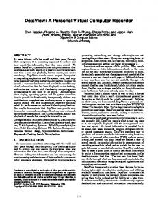
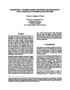
Jain et al [5] have described the basic architecture of MIPLR. This paper presents experimental results of application layer MIP-LR in a lab environment and demonstrates its performance with basic Mobile IP under several scenarios. Figure 1 shows a basic architecture for MIP-LR and its functional components. MIP-LR takes care of many of the issues associated with a survivable network such as location of the home agent, home agent vulnerability, triangular routing and tunneling associated with Mobile IP. A short description of some of the shortcomings associated with basic Mobile IP is given below. 1. Home Agent Location: The mobile’s Home Agent must be located in its home subnet. 2. Home Agent Vulnerability: There is no scheme to allow multiple, geographically distributed Home Agents located outside the Home Network to serve the user. 3. Triangular Routing: All packets destined to the mobile host must traverse its home network. 4. Tunneling: Packets destined to the mobile must be tunneled (typically by being encapsulated inside another IP packet) enroute. MIP-LR provides an efficient approach compared to MIP by taking care of forwarding, profile replication, local anchoring, and hierarchical organization. The first two limitations inhibit survivability, particularly in a military scenario where the mobile’s home network may be in a vulnerable forward area. The second two limitations imply a performance penalty and also inhibit interoperability with other protocols like RSVP which rely on inspecting the original IP packet header. A MIP-LR based mobility solution can operate in both modes: Foreign Agent (FA) mode and Co-located Care-ofaddress (Co-COA) mode. In FA mode, MIP-LR client uses the address of FA (Foreign Agent) as the care-of-address. In Co-located care-of-address mode it obtains a new IP address from the DHCP server and updates the Correspondent Host with this address. Figure 2 describes a scenario in which a MIP-LR client is subjected to inter-domain mobility, and in the process obtains IP address and sends the binding update to HLR (Home Location Register) and correspondent host it is communicating with.
Application layer MIP-LR provides a network layer independent solution but uses some of the standard architectural components of MIP-LR such as HLR (Home Location Register) and VLR (Visited Location Register). Because of network layer independence one does not need to make any significant changes to the software with the evolution of new operating system and kernel. In application layer MIP-LR, we eliminate the tunneling function and dependence on kernel by using packet capturing and mangling utility where by source and destination address of the packet can be changed thus making the application unaware of the address change. For example, Linux’s libipq and iptables utility can be used to provide the desired functionality. While providing network independent solution application-layer based MIP-LR can also support all the features provided by basic MIP-LR, such as survivability and bandwidth efficiency. Application layer MIP-LR can also inter-operate with other forms of mobility protocols such as SIP-based mobility and MMP (MicroMobility Management Protocol) [11]. In the following paragraphs we describe the details of some of the functional components of MIP-LR.
Home Network: a.b.c
HLR 2: Query 3: COA
CH
Foreign Network: j.k.l
VLR
5:Un-Encapsulated data packets sent directly to COA
4: Binding cache (COA)
Mobile Host: a.b.c.d
1: Registration: COA=j.k.l.m
Fig. 1. Basic MIP-LR Architecture
HLR 3 4. Query
LDAP DNS
LDAP DNS
Domain 1
Domain 2
HLR 4
3. Register
3. Register
5. New address DHCP
HLR 1
VLR 2
VLR 1
3. Register
HLR 2
2. Register 4. Query a.b.c.d 6. Data Packets Correspondent Host (CH)
1. Move
7. Move
Mobile Node
p.q.r.s
j.k.l.m 8. Update CH
Fig. 2. Inter-domain mobility using MIP-LR
Mobile Host: Mobile host is the client that changes subnetworks and obtains a new IP address as it moves between
3
subnets. The Mobile host updates the Correspondent Host (CH) and Location Register as soon as it obtains a new IP address while changing a subnet. This address can be obtained via DHCP or PPP server based on the type of movement (e.g., LAN, WAN). Each mobile host may be assigned with a permanent IP address that can act like a unique identifier for the mobile. But as the mobile moves around it updates the location register with the new care-of-address of the mobile. Correspondent Host: The correspondent host is the client that has ongoing communication with the mobile host. The Correspondent host queries the location register and obtains the current IP of the communicating host from the Location Register (LR) the first time it tries to set up the communication with the mobile. Any application running on a correspondent host initiates the communication using the address obtained from the location register at any particular time. The mobile’s IP address obtained from the Location Register helps to route the packets properly to the communicating host. Location Register: A Location Register (LR) is a server that gets updated with the new IP address of the mobile. It maintains a database mapping of home IP address and current IP address of the mobile. Unlike home agent in Mobile IP, Location Register is not in the data path and thus does not need to do any kind of encapsulation. Also location register does not need to be in the home subnet. LR is looked up by the correspondent host or by the mobile. In order to provide the survivability features this scheme provides multiple location registers. In that case mobile host usually registers with all the location registers associated with the mobile. Each mobile host is usually equipped with a list of location registers that can either be pre-provisioned or be obtained via DNS “SRV” mechanism. Mangler/De-Mangler: Mangler and De-Mangler are software modules that are part of correspondent host and mobile host respectively. The “iptables” based mangler changes the destination IP address of the application packet so that the packets are routed properly to the mobile host, but demangling function changes the destination address back to mobile’s original address so that application does not get affected in the process. Mangling and de-mangling software modules have been implemented using C language, although these functions can also be taken care of by NAT modules and “iptables” rules provided by Linux operating systems. PIP: PIP stands for permanent IP address. Each mobile is usually associated with a permanent IP address that is otherwise defined as home address of the mobile. A correspondent host always starts the communication with the mobile using mobile’s permanent IP address regardless of mobile’s current point of attachment. Thus as far as correspondent host’s application is concerned other part of the communicating host is the permanent IP address of the mobile. A mobile can also treat the COA it obtains in its first visited network to be the permanent IP address if it begins communicating with the correspondent host in the visited network. Application: Various kinds of non-real-time application
were tried in the laboratory environment to test continuous mobility using MIP-LR based solution. These applications include standard FTP, a customized TCP application that sends stream of bytes to the mobile host, when the MH moves to obtain a new COA. When a mobile host moves from one subnet to another, it registers its current COA with Home Location Register (HLR). When a correspondent host has a packet to send, it first queries the HLR to obtain the mobile host’s COA, and then sends packets directly to the mobile host. The mapping from the mobile host’s permanent IP address to its COA is done by the IP layer at the correspondent host and is transparent to higher-layer protocols; the reverse mapping is done at the mobile. The correspondent host caches the mobile host’s COA to avoid querying the HLR for every subsequent packet destined for the mobile host. The mobile host maintains a list of correspondent hosts with which it is in active communication and informs them if it moves to a different subnet (as is done in Mobile IPv6).
CH (IPch)
MH (IPCOA)
Application (src IPpip, dst IPch)
Application
(src IPch, dst IPpip)
LR MIP-LR Daemon
MH.COA
LR
4 TCP
UDP
UDP
TCP MH.COA
Libipq+Mangler
IP
(src IPch, dst IPpip)
(src IPcoa, dst IPch)
3
MH.PIP
IP
Libipq+ Demangler
Mangler MH-COA
MH-COA
(src IPch, dst IPcoa)
(src IPpip, dst IPch) MAC
MAC
2 1
(src IPch, dst IPcoa) MH-COA
Ippip = Mobile’s home address IPch = Correspondent host’s address IPcoa = Mobile’s care-of address
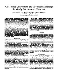
Fig. 3. Application layer MIP-LR design
A. Application Layer MIP-LR Implementation Figure 3 shows the underlying techniques of application layer MIP-LR and interaction of mangler and demangler with the application both at the mobile host and correspondent host. Mobile host does not need to be at the home network when communication begins. Figure 3 shows an instance where the mobile moves from one visited network to another. As the mobile moves to a new visited network, it registers its current COA with the HLR. However, CH only knows the permanent IP address of the mobile or its FQDN (Fully Qualified Domain Name). When the correspondent host sends a packet to mobile host, the sending application on the corresponding host uses the home address (permanent address of the mobile) as the destination address. But before the packet is sent out of MH’s interface it queries one of the HLRs that provide the current IP address of the mobile. This address is passed onto the mangler on the correspondent side that intercepts the outgoing packet and changes the destination address of the packet to that of COA of the mobile. As the packet
4
B. MIP-LR performance While MIP-LR provides survivability and redundancy, it also offers better performance compared to traditional Mo-
e0 All nodes: 192.168.x.y
e0
e0
0.1
1.254 Cross-connect
e0
1.100
e1
0.3
e0
0.2
R2
e1
ch
0.32
Hub
R1
e1
2.254
0.4
e0
R3
R4
3.254
e1
4.254
cables
e0
delay1 e1
e0
2.200
delay2 e1
100.110
Hub
200.220 Hub
Hub
e0 200.20
100.10
ha
e0
lr1
13.31
e1 e1
Ch1
Hub
3.30
e0
lr2/ap1
11.11
e1
11.64
Ch4 (COA=13.65)
mh
ESSID: ACNTestLab Key: 01010101
4.40
ap2 e1
14.41
Ch10 (COA=14.66)
Intermittent connection as 192.4.12.212
e0
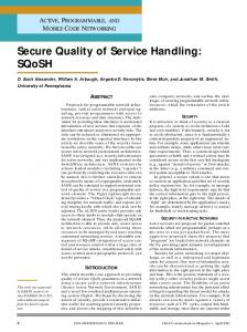
Fig. 4. MIP-LR testbed
bile IP. Using MIP-LR instead of Mobile IP one can expect to achieve a goal of 50 percentage reduction in management overhead (latency of 10.5 ms vs. baseline of 18.5 ms in MIP case for a packet size of 1Kbyte in a small campus environment). We have used SUN’s mobile IP in co-located mode for comparison. In case of Mobile IP when the mobile is resident in the foreign domain, any packet destined to mobile host traverses via the home agent. But in case of MIP-LR, the packets destined to mobile host are sent directly without suffering from the triangular routing problem. Figure 5 shows the analytical results of round-trip delay between the correspondent host and the mobile host as the distance (number of hops) between CH , HA and HA, MH is varied. As it appears the delay gets bigger as the distance is increased becasue of triangular routing. Figures 6 through 12 show different sets of measurements taken in the testbed shown in Figure 4 under different scenario. Analysis of each of set of these measurements is described below.
Mean delays of MIP and MIP-LR analytic 0.06 0.05 0.04
Delay (s)
gets routed to the proper network where the mobile host is currently resident, the demangler intercepts the packets and changes the destination address back to the original home address of the mobile. Thus the packet gets delivered to the mobile’s application with the mobile’s original PIP address as the source address. As the mobile moves to a new visited domain, and gets a new Care of Address, it registers with the HLR and also sends binding update to the communicating correspondent host. Subsequent packets from correspondent host do not need to look up to HLR before sending the packets out. As far as the application is concerned it still sends packets to the home address (permanent address of the mobile, but destination address of the packets get mangled by the “mangler” so that these can be routed properly. Demangling process is still taken care of in a similar way once the packets arrive the mobile host. Alternatively when the mobile starts the communication while in a visited network, CH can use mobile’s first COA to be its permanent address to keep the communication going in the subsequent visited networks. A laboratory testbed was created using several MIP-LR components such as HLRs, DHCP servers, mobile hosts and correspondent hosts. In order to perform a comparison with Mobile IP this testbed is also equipped with several Mobile IP components such as home agent and foreign agents in colocated care-of address mode. Figure 4 shows the MIP-LR laboratory testbed. It consists of two visited networks, and one home network. There are two home location registers denoted as lr1 and lr2. Entity “ha” is the home agent. Both lr2 and ap2 act as foreign agents in co-located mode in the two visited domains. These also have wireless interfaces that provide connectivity to the mobiles moving between two visited domains. Each mobile host has been assigned a permanent home address as a unique identifier that may not belong to any specific network domain. Mobile host maintains a list of home location registers that it can communicate with. This is obtained as part of mobile’s bootstrapping procedure. As the mobile host moves to a foreign domain, it interacts with DHCP server and obtains a new IP address. At this point it sends a register message to the Home Location Register (HLR). HLRs associate ���the � new IP address obtained with its permanent IP address . If the mobile moves in the midst of a session it sends the binding update to the correspondent host it is communicating with. We used NIST (National Institute of Standards and Techology) delay simulators (e.g., delay1 and delay2) in the path between the correspondent host, home agent and location register (lr1). These delay simulators add synthetic delays to simulate the distance between CH, and HA. R1, R2 and R3 are the Cisco routers that connect the visited subnetworks to the core network. Mobile Host mh moves between two visited domains, by connecting to “lr2” and “ap2”s interfaces.
MIP: a=b=10
0.03
MIPLR: a=b=10
0.02
MIP: a=b=5 0.01
MIPLR: a=b=5
0.00 0
256
512
768
1024
1280
Data packet length (Bytes)
Fig. 5. Analytical comparison MIP vs. MIP-LR
Figure 6 shows RTT (Round Trip Time) between CH and HA without any Mobile IP components being used. Value of NIST delay simulator “delay1” was varied in increments of 10 ms. Results show a linear increase in round-trip-time as
5
the delay increases. This delay factor within NIST simulates the distance between CH and HA.
from 0 to 40 ms. Experimental RTT appears to be same independent of type of mobility protocol (MIP or MIP-LR) being used, since the ping packets are between CH and HA, and the mobile is not involved in the communication path.
Ping CH->HA, No MIP: RTT varies linearly with payload 100
RTT (ms)
80
Ping, No M IP, M H@Home : RTT to M H is consiste ntly gre ate r than for CH
Delay1 = 0
60
Delay1 = 10
40
Delay1 = 20
60
Delay1 = 40
50
RTT (ms)
20 0 0
128 256 384 512 640 768 896 102 4
CH->HA, Delay1 = 0
40
CH->MH, Delay1 = 0
30
CH->HA, Delay1 = 20
20
CH->MH, Delay1 = 20
10
Payload (B)
0 0
Fig. 6. RTT vs. payload with delay variance
128
256
384
512
640
768
896 1024
Payload (B)
Fig. 9. RTT to MH at home Ping, CH->HA, Delay1 = 0: RTT is the same regardless of protocol 10
RTT (ms)
8 No MIP
6
MIP 4
MIP-LR
2 0 0
128
256
384
512
640
768
896 1024
Figure 9 shows that RTT from CH to MH is always more than RTT from CH to the home agent (HA) when MH is at home. Although MH and HA are in the same subnet, it takes more time since HA also happens to be a router and responds faster than the mobile host. For each case the RTT is more if an additional delay is added. This merely shows that if the distance between HA and CH is more it will increase the RTT to a great extent.
Payload (B)
Fig. 7. RTT vs. payload with zero delay Ping, No MIP, CH->MH@Home:
100 80
RTT (ms)
Figure 7 shows round trip time between CH and HA, with different payload size. The results show that the RTT does not change irrespective of the type of mobility protocol (e.g., MIP-LR, MIP or no MIP) used. Payload size was increased in an increment of 128 bytes. In this specific figure delay is set to 0. Delay being set to zero assumes that the CH is in the same network as the home agent, and thus RTT is the same regardless of the mobility protocol used.
Delay1 = 0
60
Delay1=10
40
Delay1=20 Delay1=40
20 0 0
128 256 384 512 640 768 896 1024 Payload (B)
Fig. 10. RTT to MH vs. delay and payload
RTT (ms)
Ping CH->HA, 64B packets: RTT is the same regardless of protocol 90 80 70 60 50 40 30 20 10 0
No MIP MIP MIP-LR
0
10
20
30
40
Delay1 (ms)
Fig. 8. RTT vs. Delay
Figure 8 shows RTT between CH and HA for a specific packet size (64 bytes in this case) as the delay factor is varied
Figure 10 confirms that RTT from CH to MH varies linearly with payload size and the delay factor and establishes the fact that payload traffic size and distance factor will affect the transmission delay to a great extent. Figure 11 and 12 show a comparison of RTT between CH and MH for both MIP-LR and MIP for two fixed payload size e.g., 64 bytes and 1024 bytes respectively. It shows that MIPLR outperforms the MIP as the payload size increases. As the delay factor “delay1” was varied simulating increase in distance between CH and HA, MIP-LR’s RTT is not affected because the packets to MH do not have to traverse via home agent as a result of the direct binding update from the mobile to the CH.
6
Ping, CH->MH@Foreign, Payload=64B:
RTT (ms)
M IP-LR outpe rforms M IP whe n the triangle is long 90 80 70 60 50 40 30 20 10 0
MIP MIP-LR
0
10
20
30
40
update to the communicating correspondent host directly. But in addition, MIP-LR scheme takes care of the survivability features by allocating multiple location registers and allowing the mobile to register with a multiple location registers. In MIP-LR case mangler and de-magler modules that are added to the mobile and correspondent hosts to support direct binding update are implemented at an application layer compared to the binding update mechanism in Mobile IP with router optimization where both CH and MH need to be modified at a kernel level thus making it little difficult for deployment.
Delay1 (ms)
IV. C ONCLUSION Fig. 11. RTT to MH (MIP-LR vs. MIP), 64 bytes
Ping, CH->MH@Foreign, Payload=1024B: MIP-LR outperforms MIP when the triangle is long 120
RTT (ms)
100 80 MIP
60
MIP-LR
40 20 0 0
10
20
30
40
Delay1 (ms)
We have described the preliminary design, implementation and performance results of application layer MIP-LR. This application layer approach provides a solution that works independent of kernel and operating system upgrade and provide additional features and better efficiency compared to the standard features of Mobile IP. Results from the analysis and several laboratory experiments show a marked improvement in terms of latency and throughput compared to basic Mobile IP in the same environment. An application layer MIP-LR that can take care of the continuity of the existing application and provide inherent survivability features makes it more attractive for deployment in an environment that is quasi-static in nature. R EFERENCES
Fig. 12. RTT to MH (MIP-LR vs. MIP), 1024 bytes [1]
Table 1 shows the MIP-LR signaling size in bytes. There are mainly 5 different type of signaling messages in MIP-LR. MIPLR registration request is about 52 bytes, where as registration reply is about 50 bytes UDP packets. MIP-LR query made by CH is about 24 bytes. LR notifies the CH about the MH location using a 28 byte response packet. As the MH gets a new address it notifies the CH and LR using a binding update message which is about 28 byte, an additional 28 byte header(20 byte IP and 8 byte UDP). While MIP-LR can by itself provide support for continuous mobility, it can also coexist with other forms of macro mobility solution such as SIPbased mobility (SIPMM) and micro-mobility solution such as MMP to provided an integrated scheme. MIP-LR scheme’s binding update mechanism is very similar to the binding update scheme used for Mobile IP with route optimization, where the the mobile host sends a binding
TABLE I MIP-LR M ESSAGES S IZE
MIP-LR Message Registration Reply BINDING UPDATE QUERY RESPONSE
Size (Bytes) 52 50 28 24 28
W/Overhead 80 78 56 52 56
C. Perkins, “IP mobility support for IPv4,” RFC 3344, Internet Engineering Task Force, Aug. 2002. [2] R. Ramjee, T. F. LaPorta, L. Salgarelli, S. Thuel, K. Varadhan, and L. Li, “IP-based access network infrastructure for next-generation wireless networks,” IEEE Personal Communications Magazine, vol. 7, pp. 34–41, Aug. 2000. [3] A. Campbell, J. Gomez, S. Kim, A. G. Valk, C.-Y. Wan, and Z. R. Turnyi, “Design, implementation, and evaluation of cellular IP,” IEEE Personal Communications Magazine, vol. 7, pp. 42–49, Aug. 2000. [4] S. Das, A. Misra, P. Agrawal, and S. K. Das, “Telemip: Telecommunications-enhanced mobile IP architecture for fast intradomain mobility,” IEEE Personal Communications Magazine, vol. 7, pp. 50–58, Aug. 2000. [5] R. Jain, T. Raleigh, D. Yang, L. F. Chang, C. J. Graff, M. Bereschinsky, and M. Patel, “Enhancing survivability of mobile Internet access using mobile IP with location registers,” in Proceedings of the Conference on Computer Communications (IEEE Infocom), (New York), Mar. 1999. [6] E. Wedlund and H. Schulzrinne, “Mobility support using SIP,” in 2nd ACM/IEEE International Conference on Wireless and Mobile Multimedia (WoWMoM), (Seattle, Washington), Aug. 1999. [7] F. Vakil et al., “Supporting mobility for TCP with SIP,” internet draft, Internet Engineering Task Force, Nov. 2000. Work in progress. [8] P.-Y. Hsieh, A. Dutta, and H. Schulzrinne, “Application layer mobility proxy for real-time communication,” in World Wireless Congress, 3G Wireless, (San Francisco), Delson, Delson, May 2003. [9] R. J. Stewart, Q. Xie, K. Morneault, C. Sharp, H. Schwarzbauer, T. Taylor, I. Rytina, and M. Kalla, “Stream control transmission protocol,” RFC 2960, Internet Engineering Task Force, Oct. 2000. [10] S. Das, A. McAuley, A. Misra, and S. Das, “A comparison of mobility protocols for quasi-dynamic networks,” in 2000 IEEE Wireless Communications and Networking Conference, WCNC 2000, pp. 1569– 1574, Sept. 2000. [11] D. Wong, A. Dutta, J. Burns, K. Young, and H. Schulzrinne, “A multilayered mobility management scheme for auto-configured wireless IP networks,” IEEE Wireless Magazine, Oct. 2003.