Scientific Programming 17 (2009) 199–208 DOI 10.3233/SPR-2009-0266 IOS Press
199
Implementation and performance modeling of deterministic particle transport (Sweep3D) on the IBM Cell/B.E. Olaf Lubeck a , Michael Lang a,∗ , Ram Srinivasan b and Greg Johnson c a Los
Alamos National Laboratory, Los Alamos, NM, USA Fort Collins, CO, USA c Google Mountain View, CA, USA b Intel
Abstract. The IBM Cell Broadband Engine (BE) is a novel multi-core chip with the potential for the demanding floating point performance that is required for high-fidelity scientific simulations. However, data movement within the chip can be a major challenge to realizing the benefits of the peak floating point rates. In this paper, we present the results of implementing Sweep3D on the Cell/B.E. using an intra-chip message passing model that minimizes data movement. We compare the advantages/disadvantages of this programming model with a previous implementation using a master–worker threading strategy. We apply a previously validated micro-architecture performance model for the application executing on the Cell/B.E. (based on our previous work in Monte Carlo performance models), that predicts overall CPI (cycles per instruction), and gives a detailed breakdown of processor stalls. Finally, we use the micro-architecture model to assess the performance of future design parameters for the Cell/B.E. micro-architecture. The methodologies and results have broader implications that extend to multi-core architectures. Keywords: Cell/B.E. Broadband Engine (CBE), performance modeling, Monte Carlo, Sweep3D
1. Introduction Recent technology advances in power efficient single chip multi-processors (CMPs) have led many researchers in the computer and computational sciences to embrace the implementation and performance challenges that are brought to the forefront by these chips. Many of the parallelism and data partitioning issues have been investigated by the high performance computing community for massively parallel computing technologies, but the unprecedented degree of VLSI integration has changed the relative performance costs associated with communication, floating point computation, memory access and memory capacity. In particular, the Cell/B.E. is an intriguing new design with 204 Gflops (aggregate single precision) peak performance [5,13], but more importantly has an internal bus bandwidth of 205 GB/s. Although it was primarily designed for the game market, the architecture, performance and marketability of the chip make it an at* Corresponding author: Michael Lang, Los Alamos National Laboratory, TA3 Bldg 2011, Los Alamos, NM 87545, USA. Tel.: +1 505 665 5756; Fax: +1 505 665 4939; E-mail:
[email protected].
tractive exploration area for high-end technical computing. For example, Los Alamos National Laboratory has based its petaflop-scale system, Roadrunner [2], on Cell/B.E. The system built by IBM will use Cell/B.E.s paired with conventional AMD Opteron cores. Nevertheless, there are interesting questions and challenges that arise regarding Cell/B.E.s suitability for scientific applications. In this paper, we investigate some of these challenges by focusing on Sweep3D, an application with computational features that represent a significant part of Los Alamos National Laboratory’s workload and that of many physical simulations in general. An early paper [17] describing the performance of small kernels executing on the Cell/B.E. simulator pointed out its potential for scientific computations. More recent work [12] describes an implementation of Sweep3D using a coordinated master–worker threading model that obtained good performance but transferred a significant multiple of the application’s total data volume between different memories in the Cell/B.E. and was limited by memory-to-local store bandwidth. Our paper furthers the investigation into the suitability of the Cell/B.E. and provides a unique
1058-9244/09/$17.00 © 2009 – IOS Press and the authors. All rights reserved
200
O. Lubeck et al. / Implementation and performance modeling of deterministic particle transport
insight by considering a message-passing programming model between the Cell/B.E. cores. This paradigm minimizes data movement by using wellunderstood data partitioning strategies. Intra-Cell/B.E. message passing communication routines are developed allowing data communication proportional to the partition’s surface (rather than the volume) to be transferred between memories. Since most cluster-based applications have been developed with message-passing models, this programming paradigm appears to be a general and evolutionary software development path for these applications. The performance of our single Cell/B.E. implementation is modeled using a novel Monte Carlo method that we previously developed for in-order micro-architectures [15,16]. In this paper we use it to assess the effectiveness of enhancements to the architecture. The contributions of this paper are as follows: • Implementation and performance benchmark of an intra-chip message-passing paradigm for the Cell/B.E. using Sweep3D. • Comparison of this paradigm with previous master–worker task paradigm and comparison of the Cell/B.E. performance with other multi-core architectures. • Performance models applied to the Cell/B.E. micro-architecture. • Predictions of performance for future architectural improvements.
2. Cell broadband architecture Figure 1 shows a block diagram of the Cell/B.E. The Cell/B.E. is a nine-core heterogeneous processor [3–5,7,8,13]. One of the cores is based on the 64-bit PowerPC instruction set and is called the Power Processing Element (PPE). The PPE employs a dualissue, in-order, 2-way simultaneous multi-threading (SMT) pipeline. The other eight cores are homogeneous, implement a new instruction set, and are called Synergistic Processor Elements (SPEs). The SPEs feature a dual-issue, in-order pipeline with support for vector (or SIMD) operations. The peak floating-point (FP) performance of the SPEs is 204.8 Gflops/s at single-precision and 14.8 Gflops/s at double-precision. The PPE runs the operating system and creates threads on the SPEs. Communication between the PPE and the SPEs is possible through a high speed bus called the Element Interconnect Bus (EIB). The EIB is capable of moving 96 bytes of data every cycle. The Cell/B.E. also features an on-chip memory controller and I/O controller which are connected to the EIB. There are eight SPEs in a Cell/B.E. The SPEs consist of two main blocks – a Synergistic Processor Unit (SPU) and a Memory Flow Controller (MFC). The SPU is the computation engine of the SPE, while communication is handled by the MFC. Since the SPU utilizes a statically scheduled, in-order pipeline, the hardware does not reorder instructions at runtime to minimize stalls. The compiler must schedule instructions
The outline of this paper includes the following sections: – Section 1 – This introduction. – Section 2 – A brief summary of the cell broadband architecture. – Section 3 – A description of the Sweep3D algorithm. – Section 4 – The intra-Cell/B.E. message passing programming model and a comparison to previous paradigms. – Section 5 – A description of the Cell/B.E. performance model, and its validation and predictions of Sweep3D performance on future microarchitecture features. – Section 6 – Basic performance results and a comparison to previous work. – Section 7 – Conclusions and future work.
Fig. 1. Cell/B.E. architecture.
O. Lubeck et al. / Implementation and performance modeling of deterministic particle transport
appropriately to minimize stalls. To help this effort, the architecture provides a large register file with 128 128-bit registers. No distinction between FP and integer registers is made by the architecture. In addition to the large register file, each SPU includes a single-level, 256 kB memory called the Local Store (LS). The LS is the only memory that can be directly accessed by the SPU and holds both the program and data. Since the LS is very limited in size, mechanisms to quickly transfer data to/from the LS are required. This is provided by the MFC in the form of Direct Memory Access (DMA). DMA requests can be initiated by both the PPE and the SPU. Once a request has been queued, the requester is free to continue with computation. Completion of DMA can be determined by querying the appropriate status ports (or channels). Besides DMA, the MFC supports mailbox and mutex synchronization mechanisms. The execution units (EU) in the SPU are organized into two logical partitions called even and odd pipelines [3,5]. Two instructions may issue each cycle provided that they issue to EUs on different pipelines. All EUs are fully pipelined with the exception of the double precision floating point (FPD). The FPD is the only unit that is partially pipelined and the only unit that has an effect on global instruction issue. When an instruction is issued to the FPD, no other instruction can be issued for the next 6 cycles. All SPU instructions are 32-bits wide and two successive instructions are fetched every cycle that the pipeline is not stalled. Stalls in the pipeline occur due to (1) wrong instruction mapping, (2) unresolved dependence, (3) wrongly speculated branch, and (4) lack of instructions in the instruction buffer (or run-out). As an example of wrong instruction mapping, the instruction pair (FP, LOAD) can be issued in one cycle, while the pair (LOAD, LOAD) requires two cycles to issue. Stalls due to unresolved dependence are caused by RAW hazards. For example, if a load instruction to register $8 is immediately followed by an add instruction that consumes $8, the add will have to stall for six cycles (the latency of the load to LS). Since the SPUs do not have a dynamic branch predictor, the default prediction for a branch is not-taken. Therefore, if a branch is taken, there is an 18 cycle penalty to flush the pipeline and restart execution along the correct path. However, to help mitigate the high cost of taken branches, a software-based hinting mechanism is supported by the architecture. If the hint is correct and occurs sufficiently ahead of the branch, the branch penalty is reduced to zero cycles. The last stall con-
201
dition occurs when there are no instructions in the respective buffers to feed the pipeline. This is possible because access to the LS is arbitrated between DMA, load/store operations, hint fetch and demand fetch for instructions, with the latter having the least priority. However, in practice we have found that the performance effect of runout is negligible for Sweep3D because the instruction line buffer (ILB) that holds instructions waiting to enter the pipeline, can buffer up to 112 instructions. If runout is an issue for other applications the ifetch instruction can be used [3]. A major feature of the instruction set for scientific computations is that all floating point instructions are SIMD – 4 single precision or 2 double precision results are produced from each SIMD instruction. SIMD memory instructions load/store data that are located in consecutive memory addresses. In the vernacular of vector architectures, this amounts to a non-strided vector load/store in the LS. There are no scalar floating pointing instructions and no strided or gather/scatter memory operations from the LS. The data layout and access patterns of the application must be constrained to get optimal performance from the SIMD instructions. We now describe the Sweep3D algorithm and then proceed to address the optimization choices that relate to the Cell/B.E. architecture reviewed in this section.
3. Sweep3D algorithm In this section, we give a brief explanation of the basic algorithm and data dependences in the Sweep3D application (a similar explanation is also given in [6]). Sweep3D is a deterministic implementation of discrete ordinates neutron transport [9]. The major field to be calculated is Ψ which represents the particle flux at spatial point (x, y, z) with energy, E, traveling in direction Ω. The basic problem is discretized spatially into micro-blocks (in previous papers these are referred to as “cells” but to avoid confusion with the Cell/B.E., micro-blocks will be used), discrete angles and energy groups and is inherently 5 dimensional. However, Sweep3D is a simplification that involves one energy group and is thus four dimensional. The numerical solution of the transport equation involves an iterative procedure that has been referred to as the source iteration. The vast majority of the time is spent in a “sweep” computation which involves calculations iterating through the spatial coordinates for each discrete angle. At a given angle, each micro-block has a flux
202
O. Lubeck et al. / Implementation and performance modeling of deterministic particle transport
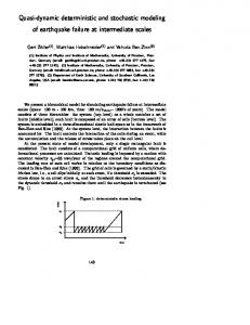
Fig. 2. Sweep calculation. Not all micro-blocks can be computed simultaneously. Dependences between micro-blocks cause a diagonal wavefront that can be computed in parallel. The figure is for an angle starting in the top left corner. Each shaded micro-block on the diagonal needs an inflow from the micro-block on its North and West and passes data to micro-blocks on its South and East.
conservation equation with seven unknowns – the flux at each of six micro-block faces and the center. Boundary conditions on the incoming flux at a given angle complete a closed form solution. Figure 2 shows the spatial dependences (in two dimensions only) for an angle starting at the top left corner. Multiple angles start in the same quadrant (corner) and can be computed simultaneously, but angles starting in different quadrants are dependent on previous quadrants. Boundary fluxes are known at the faces of microblocks at the top row and left column. Conservation equations allow the flux at neighboring downstream micro-blocks to be computed at their centers and outgoing faces. The flux across an outgoing face becomes the incoming flux for a neighbor’s face and the computation proceeds in a diagonal wave across the micro-blocks. Conceptually a lower triangular system of equations could be explicitly written and solved, but Sweep3D simply solves for the unknown fluxes at each micro-block in place (i.e. in the original arrays). This computation over all micro-blocks at each angle is known as a “sweep”. One feature of the sweep algorithm is that the angles are represented in two different ways – first as discrete angles (six per octant per point for this investigation), and second, as four moments (per point) of a spherical harmonic series – Sweep3D transitions between the two different representations. All 6 angles for each octant are computed in 6 sweeps in physical space while transformations to and from spherical harmonics are done before and after each octant’s 6 sweeps. Algorithmic data dependences limit the amount of parallelism in the application. Octants depend on previous ones, but the flux for all angles in each octant
can be calculated simultaneously. Unlike many explicit PDE solvers where all micro-blocks can be computed simultaneously, the parallelism in spatial coordinates is limited to those points that lie on the same diagonal. In two dimensions, this is the diagonal line in Fig. 2. In three dimensions, the micro-blocks that can be simultaneously computed are in a diagonal plane. In summary, the dimensionality of spatial concurrency in Sweep3D is one order less than the problem’s dimensionality [9]. Because of this, Sweep3D is typically parallelized across multiple processors (in a cluster) by decomposing in a two-dimensional processor grid. Two spatial dimensions (I × J) are partitioned into sub-domains across a Px by Py processor grid (Fig. 3). However, parallel efficiency is drastically limited if neighbor information along the edges of a sub-domain is not communicated until all micro-blocks in the subdomain volume are computed. Therefore, a strategy is employed where a subset of the sub-domain is computed and then communicated. The subset is a block of planes in the K direction. Varying the number of planes in K-blocks changes the relative ratio of compute-to-communicate times. The performance of this parallelization strategy has been modeled and validated [6]. In a later section, we apply this model to our Sweep3D implementation on the Cell/B.E. to predict its performance on multiple SPUs within a single Cell/B.E.
4. Sweep3D programming models for the Cell/B.E. A number of papers have been published on programming strategies for the Cell/B.E. [1,4,10,17] that provide ideas for the coordination of the heterogeneous cores and management of the separate memories. In this investigation, we considered three major issues that affect the choice of programming model. First, a realistic problem size for Sweep3D requires a multiple-processor implementation on a large cluster. Consideration of practical solution times limits subdomain sizes to within an order of magnitude of 104 micro-blocks on current parallel systems. Longer solution times result if subdomains are smaller because the execution becomes communication dominant, and larger domains result in a compute dominant execution. The subdomain problem size becomes an issue in the Cell/B.E. because the time for DMA accesses to main memory and the local stores of other SPUs must be balanced with the compute time within a SPU. Performance models of both the Cell/B.E. micro-
O. Lubeck et al. / Implementation and performance modeling of deterministic particle transport
203
Fig. 3. A 2D decomposition of Sweep3D on 8 SPUs showing the pipelining of computations in the K direction (grayed areas on each SPU on the right). The computation began at the top corner in the foreground SPU and proceeds in the direction of the arrows so that each SPU is simultaneously computing a different K-block. For comparison, the left picture shows the two processors that simultaneously compute subdomains in the non-pipelined case at the completion of the foreground processor.
architecture and the multiple-processor scalability (addressed in a later section) will allow us to choose parameters that optimize for time. Secondly, minimizing memory traffic is the key concern. The ratio of loads to floating points operations (64 bit) in Sweep3D is roughly 1:1. A Cell/B.E. implementation of Sweep3D where all loads are coming from the main memory will be bandwidth limited. Specifically, since the main memory bandwidth is 25 GB/s, double precision floating point applications (with this 1:1 ratio) are limited to 3 Gflops/s. More importantly, planned performance enhancements for the Cell/B.E. for double precision floating point will not lead to improved application performance above 3 Gflops. Our choice of programming model minimizes data movement (maximizes the reuse of data in the local store). Finally, individual SPU performance requires a viable vectorization strategy for the SIMD instructions and instruction pipelining to hide local store memory latency. Vector and data-parallel algorithms for many scientific applications have been extensively researched (including Sweep3D [6]). As pointed out by the designers of the Cell/B.E. [4], a spectrum of parallelism must be exploited from instruction-level to thread-level to multi-core to multi-processor. We will visit the area of pipeline stalls in the vector code later in this paper where our micro-architecture model gives a breakdown of stall conditions. These three issues lead us to the following programming decisions: 1. A SPU centric implementation – all computational work is done on the SPU.
2. Balance computation time of the subdomain volume with communication time of the subdomain’s surface. 3. Each SPU is a distributed memory computational resource with its own subdomain. 4. Retain the original MPI message passing model [14]. 5. Vectorization will be done over angles variable. 6. Use main memory as a backing store to mitigate the limited 256 kB of local store. A SPU centric implementation allows the main computing power of the Cell/B.E. to be utilized. We avoid the master/worker programming model where the SPUs can be starved waiting for data and control messages from the PPE. We balance the computation and communication times by sending a full K-block to each SPU and then only communicating the resulting surfaces to the neighboring SPUs. In this way we treating each SPU as a separate computation resource and retain the MPI [14] message passing model. This model did require the development of a library of SPU-to-SPU communication routines that implements the semantics of blocking MPI send/receives using the atomic mutex operations and SPU–SPU DMA capabilities of the Cell/B.E. The performance of the communication library will be visited in Section 6.2. To use the SPU optimally the SIMD units must be fully exploited. In our case the contribution to the flux from each angle for a given octant can be done concurrently. To vectorize across the angles we must reorder the loops in Sweep3D such that the loop on angles is the inner most. Since there are six angles
204
O. Lubeck et al. / Implementation and performance modeling of deterministic particle transport
per octant and 2 double precision floating points per SIMD instruction, the angle iterations are completely unrolled and consists of three pipelined vectors with 2 elements each. When the contributions of the six angles are transformed into the spherical harmonic moments, a vector reduction into a scalar coefficient occurs. Finally, we address the problem sizes that can be accommodated by the limited amount of local store (256 kB). The largest problem size that we can execute is 1000 micro-blocks per SPU or 8000 per Cell/B.E., as we stated above, this is in agreement with typical processor subdomain sizes that are used in practice. However, with additional requirements of time dependence, more angles, and multiple energy groups additional memory will be needed. Therefore, we use the main memory as “backing store” for a SPU’s local store. In this implementation, we define a SPU’s computational work unit as one K-block (see Fig. 3) which is read and written from the backing store. This solution does require the total data volume to be DMA’s to the main memory over time, but the computational granularity between DMAs is parameterized by the K-block size and the total data movement is still orders of magnitude less than previous implementations. We now proceed to analyzing the performance of optimized Sweep3D using the micro-architecture model as a tool, and further to look at the performance increase a fully pipelined double precision floating point would yield for this application.
5. Performance modeling the micro-architecture of the Cell/B.E. In previous work [15,16], we have described a novel modeling methodology for predicting the per-
formance of applications executing on in-order microarchitectures. The method characterizes the application in terms of probability distribution functions and uses Monte Carlo sampling methods to predict the CPI (cycles per instruction) of an application in a matter of seconds (4–6 orders of magnitude faster than a cycle accurate simulation). The method has been validated for the Cell/B.E. architecture where it was found to have a typical prediction error of 3–4%. The predictions on the Cell/B.E. take about 2 s of computer time. In this section, we apply the model to our optimized version of Sweep3D to show a breakdown of the pipeline stall conditions in a SPU that contribute to the CPI. Figure 4 shows that the major contribution to stalls comes from the 64-bit floating point functional units. The current Cell/B.E. stalls instruction issue for 7 clocks following a double-precision floating point instruction. Future versions of the Cell/B.E. will correct this problem to reduce both the total FP latency as well as improve the issue rate to one every clock. The model predicts a 2× improvement for Sweep3D with the improved floating point. Figure 5 shows a detailed breakdown of the dependence stalls categorized by the instruction causing the stall. Very few stalls are associated with memory accesses to the local store (which has a 6 cycle latency). Most stalls are coming from dependences in the floating point instructions. The inner loops of Sweep3D are unrolled 3 times (corresponding to the 3 vectorized angle calculations). Three consecutive SIMD instructions are independent, but the fourth uses results from the first causing the FPD dependence stalls. The improved floating point reduces the 64-bit FP latency (and the overall execution time of Sweep3D), but causes more dependence stalls because the issue rate is higher. For a Sweep3D problem size with more angles, the inner
Fig. 4. CPI breakdown of optimized Sweep3D.
O. Lubeck et al. / Implementation and performance modeling of deterministic particle transport
Fig. 5. CPI breakdown of dependence stalls associated with instruction classes.
loops would be unrolled more resulting in less dependence stalls. In other words, more angles could be done with little or no extra cost.
6. Performance and results We have implemented a C version of Sweep3D that is vectorized using 64-bit floating point. The code was compiled with the native gcc compiler with –O2 optimization and uses libraries in the SDK2.1 toolkit. We found no benefit from the XLC compiler due to the hand tuned implementation. For those who have detailed experience with Sweep3D runtime parameters, the following timings are with fixups and dsa turned off. Those features are not implemented in the current code. 6.1. Single SPU performance Single SPU sweep computation times for our implementation are given in Table 1. Timings were measured with a hardware countdown decrementer that has a resolution of 14.318 MHz (224 clock periods). Measurements were taken for 1000 micro-blocks and 6 angles per octant and the time per sweep loop was computed. As we noted above, 99% of Sweep3D time is contained in the three loops that comprise the “sweep” computations. Loop 1 refers to the transformation from spherical harmonics to angles. Loop 2 is the flux calculation. Loop 3 is the transformation back to spherical harmonics and contains a vector sum reduction. Column 2 shows the number of SIMD instruction issued in each loop, column 3 shows the type of SIMD operation. Column 4 shows the best time for that loop
205
where we compute the best time as 8 clocks per double precision floating point SIMD instruction. (Recall that this is the fastest issue rate for 64-bit floating point operations.) The double precision reciprocal is an inline function and has 7 SIMD floating point ops. Finally column 5 shows the measured time for each loop, and column 6 is the ratio of best to actual. As a basis for comparing the performance of the SPU core to conventional processors, we show results in Table 2 for a 10×10×10 problem. This is the largest problem size that fits in SPU local store and would reside in cache on the Itanium and Opteron. A single SPU core has approximately the same performance as a conventional core. We note that no time has been spent in hand optimizing the Itanium or Opteron versions. 6.2. Intra-Cell/B.E. message passing performance For this work we implemented the MPI functions, MPI_Send, MPI_Recv, MPI_Bcast, MPI_Barrier and MPI_Allgather [14]. The basic methodology is to invoke a send/receive function from the SPU that passes messages to the destination SPU over the EIB. For a MPI_Send or MPI_Receive, the SPUs signal each other using mutex locks and a DMA GET is initiated by the receiver. In our implementation, we copy the application data to a communication buffer using the library function memcpy which caused a performance bottleneck. We wrote a specific memcpy to handle aligned arrays that eliminated the problem. For use in Cell/B.E. clusters, the PPU acts as an MPI server. The MPI function decides if the communication is internal or external to the Cell/B.E. In the external case the sending SPU DMAs data to main memory and then signals the PPE (using mutex locks) to initiate a standard MPI send. The receiving PPE–SPU takes corresponding actions. As expected, the intra-Cell/B.E. communications are orders of magnitude faster than the inter-Cell/B.E. communications. We report only on single Cell/B.E. scaling in this paper. Figure 6 contains times for an intra-Cell/B.E. send/receive pair using our library. The linear fit to the data shows a startup time of 1.2 µs and a slope corresponding to a communication rate of 12 GB/s. 6.3. Performance on multiple SPUs (weak scaling) Table 3 contains the times for multiple SPUs in a single Cell/B.E. The “best” time is computed with a parallel efficiency model [6] that accounts for the lim-
206
O. Lubeck et al. / Implementation and performance modeling of deterministic particle transport Table 1 Single SPU times (clock periods) for the 3 sweep loops
Loops
Number of SIMD 64-bit fp
Type of SIMD operations
Best time (cps)
Actual time (cps)
Percent (%)
Loop 1 Loop 2 Loop 3
9 30 + 3 reciprocals 22
9 mul-add 42 mul or add, 9 mul-add 16 add, 6 mul-add
72 408 176
106 451 239
68 90 74
Table 2 Single SPU times for cache sized problem on various cores Processor Single SPU Single core Itanium 2 Single core Opteron
Table 3 Cell/B.E. performance for 1–8 SPUs
Time (ms)
# SPUs – prob size
23 29 19
Time (ms)
Model time (ms)
Best time (ms)
1 – 5 × 5 × 400 2 – 10 × 5 × 400
248 263
248 264
248 250
4 – 10 × 10 × 400 8 – 20 × 10 × 400
268 277
267 274
253 260
Table 4 Comparison for 50 × 50 × 50 problem size and validation of the model on the improved PowerXCell8i
Cell/B.E. PowerXCell8i
Previous Sweep3D [4]
Our optimization of Sweep3D
1.3 s N/A
0.37 s 0.19 s
6.4. Results and comparison to previous work
Fig. 6. Intra-Cell/B.E. send/receive times as a function of message size.
its on concurrency due to the data dependences described in a previous section, but assumes that the intra-Cell/B.E. communication and the main memory reads/writes take no time. The model time gives the predicted time assuming communications. The measured times are for 10 iterations with fixups and dsa off. The problem size on a single SPU is 5 × 5 × 400 and the overall problem size scales linearly with the number of SPUs. The scalability from 1 to 8 SPUs is in good agreement with the performance model. The loss of about 9% performance from the best time is due to communication overhead. It bears repeating that the Sweep3D algorithm is not 100% parallel because of the wavefront dependences and the best time is not constant with increasing size and number of SPUs.
In Section 5 using the model we predicted a 2× improvement for Sweep3D with the improved floating point. The model was recently validated when we ran on the updated version of Cell/B.E., the PowerXCell8i. For a 50 × 50 × 50 input we see 0.37 s on the Cell/B.E. and 0.19 s on the PowerXCell8i as shown in Table 4. Also shown for comparison is the results for the problem size reported in a previous study [12]. The performance gain over the previously reported version stems from the data movement, this is the major difference between the implementations. In the previous work the researchers employed a master–worker tasking model where the PPU dynamically coordinated tasks among the SPUs. A computational unit of work consisted of a single line of micro-blocks in the I direction for a given (J, K). This requires the (J, K) line and upstream lines corresponding to (J −1, K) and (J, K −1) to be exchanged between main memory and a SPU’s local store. Integrated over all (J, K) pairs, the amount of data transferred is a large multiple of the total data volume of Sweep3D. Our implementation moves the resulting faces through the high speed EIB and takes the PPE out of the critical path, only using it for initialization and allocation of blocks of main memory.
O. Lubeck et al. / Implementation and performance modeling of deterministic particle transport
7. Conclusions and future work In this paper we have shown that extending the flat Sweep3D programming model to the Cell/B.E. results in excellent performance on a single socket. We compare favorably to previous work done in a client server type model reported in [12]. We have validated the Monte Carlo performance model of the Cell/B.E. micro-architecture and have shown that the predicted 2× benefit from double precisions pipelining exists in the PowerXCell8i. Future work includes investigating the scaling of on a petaflop-scale hybrid cluster, Roadrunner [2]. This will be accomplished by moving to a hybrid MPI for the Cell/B.E. developed by the PAL team at Los Alamos National Laboratory. The Cell/B.E. Messaging Layer (CML) [11] is an open-source minimal MPI layer for the Cell/B.E. that was inspired by the work in this paper. The hybrid version will allow each SPU to have an individual MPI rank and send messages across all of the 97,920 SPUs on the Roadrunner system regardless of their location.
Acknowledgments This work benefited greatly from collaborations with the other members of the Performance and Architecture Lab (PAL) at LANL; Adolfy Hoisie, Darren Kerbyson, Scott Pakin, Kevin Barker, Jose Sancho and Kei Davis. This work was funded in part by Department of Energy, Advanced Simulation and Computing Program.
References [1] J. Balart, M. Gonzalez, X. Martorell, E. Ayguade, Z. Sura, T. Chen, T. Zhang, K. O’Brien and K. O’Brien, A novel asynchronous software cache implementation for the Cell-BE Processor, in: Proceedings of the 2007 Workshop on Languages and Compilers for Parallel Computing (LCPC’07), Urbana, IL, USA, October 2007. [2] K.J. Barker, K. Davis, A. Hoisie, D.J. Kerbyson, M. Lang, S. Pakin and J.C. Sancho, Entering the Petaflop era: The architecture and performance of Roadrunner, in: Proceedings IEEE/ACM Supercomputing, SC08, Austin, TX, USA, November 2008. [3] A.E. Eichenberger, K. O’Brien, K. O’Brien, P. Wu, T. Chen, P.H. Oden, D.A. Prener, J.C. Shepherd, B. So, Z. Sura, A. Wang, T. Zhang, P. Zhao and M. Gschwind, Optimizing compiler for the cell processor, in: Proceedings of the International Conference on Parallel Computing Technologies (PACT 2005), St. Louis, MO, USA, September 2005.
207
[4] M. Gschwind, The cell broadband engine: Exploiting multiple levels of parallelism in a chip multiprocessor, International Journal of Parallel Programming 35(3) (2007), 233–262. [5] M. Gschwind, IBM, H.P. Hofstee, B. Flachs, M. Hopkins, Y. Watanabe and T. Yamazaki, Synergistic processing in cell’s multicore architecture, IEEE Micro 26(22) (2006), 10–24. [6] A. Hoisie, O.M. Lubeck and H.J. Wasserman, Scalability analysis of multidimensional wavefront algorithms on large-scale SMP clusters, in: Proceedings of the Frontiers of Massively Parallel Computing (FMPC), Annapolis, MD, February 1999. Available from: http://www.c3. lanl.gov/PAL/publications/papers/Hoisie1999:Sweep3D.pdf. [7] J.A. Kahle, M.N. Day, H.P. Hofstee, C.R. Johns, T.R. Maeurer and D. Shippy, Introduction to the cell multiprocessor, IBM Journal of Research and Development 49(4) (2005), 589–604. [8] M. Kistler, M. Perrone and F. Petrini, Cell multiprocessor communication network: Built for speed, IEEE Micro 26(3) (2006), 10–23. Available from: http://hpc.pnl.gov/people/fabrizio/papers/ieeemicro-cell.pdf. [9] K.R. Koch, R.S. Baker and R.E. Alcouffe, Solution of the firstorder form of the 3-D discrete ordinates equation on a massively parallel processor, Transactions of the American Nuclear Society 65 (1992), 198. [10] A.K. Nanda, J.R. Moulic, R.E. Hanson, G. Goldrian, M.N. Day, B.D. D’Amora and S. Kesavarapu, Cell/B.E. blades: Building blocks for scalable, real-time, interactive, and digital media servers, IBM Journal of Research and Development 51(5) (2007), 573–582. Available from: http://www.research.ibm.com/journal/rd/515/nanda.pdf. [11] S. Pakin, Receiver-initiated message passing over RDMA networks, in: Proceedings of the 22nd IEEE International Parallel and Distributed Processing Symposium (IPDPS’08), Miami, FL, April 2008. Available from: http://www.c3. lanl.gov/PAL/publications/papers/Pakin2008:cellmsg.pdf. [12] F. Petrini, G. Fossum, J. Fernandez, A.L. Varbanescu, M. Kistler and M. Perrone, Multicore surprises: Lessons learned from optimizing Sweep3D on the cell broadband engine, in: Proceedings of the International Parallel and Distributed Processing Symposium (IPDPS’07), Long Beach, CA, USA, March 2007. Available from: http://hpc.pnl.gov/people/fabrizio/papers/ipdps07sweep3d.pdf. [13] D. Pham, S. Asano, M. Bolliger, M.N. Day, H.P. Hofstee, C. Johns, J. Kahle, A. Kameyama, J. Keaty, Y. Masubuchi, M. Riley, D. Shippy, D. Stasiak, M. Suzuoki, M. Wang, J. Warnock, S. Weitzel, D. Wendel, T. Yamazaki and K. Yazawa, The design and implementation of a firstgeneration CELL processor, in: Proceedings of IEEE International Solid-State Circuits Conference (ISSCC’05), San Francisco, CA, USA, February 2005, pp. 184–185. [14] M. Snir, S. Otto, S. Huss-Lederman, D. Walker and J. Dongarra, MPI: The Complete Reference, 2nd edn, Vol. 1, The MPI Core, The MIT Press, Cambridge, MA, September 1998. [15] R. Srinivasan, J. Cook and O. Lubeck, Ultra-fast CPU performance prediction: Extending the Monte Carlo approach, in: Proceedings of the IEEE International Symposium on Computer Architecture and High Performance Computing (SBACPAD), Brazil, October 2006.
208
O. Lubeck et al. / Implementation and performance modeling of deterministic particle transport
[16] R. Srinivasan and O. Lubeck, MonteSim: a Monte Carlo performance model for in-order microarchitectures, SIGARCH Computer Architecture News 33(5) (2005), 75–80; http://doi.acm.org/10.1145/1127577.1127592. [17] S. Williams, J. Shalf, L. Oliker, S. Kamil, P. Husbands and
K. Yelick, The potential of the cell processor for scientific computing, in: Proceedings of ACM International Conference on Computing Frontiers (CF’06), Ischia, Italy, May 2006.