Code Patric for Studies of Transverse Coherent Instabilities in the Fair Ringsâ ... Steering scripts written in Python to perform parameter scans and determine ...
Proceedings of ICAP 2006, Chamonix, France
WEA3MP04
Implementation and Validation of Space Charge and Impedance Kicks in the Code Patric for Studies of Transverse Coherent Instabilities in the Fair Rings∗ O.Boine-Frankenheim, V. Kornilov, GSI, Planckstr.1, 64291 Darmstadt, Germany Abstract
• Additional effects that are important over long time scales, like kinetic IBS. • Modular implementation using C++ classes. Steering scripts written in Python to perform parameter scans and determine and display stability boundaries.
Simulation studies of the transverse stability of the FAIR synchrotrons have been started. The simulation code PATRIC has been developed in order to predict coherent instability thresholds with space charge and different impedance sources. Some examples of code validation using the numerical Schottky noise and analytical stability boundaries will be discussed.
In the following some of the underlying beam physics models and their numerical implementation in PATRIC will be described.
INTRODUCTION
SPACE CHARGE KICKS IN PATRIC
The FAIR synchrotrons will be operated with medium energy, intense heavy ion beams of low momentum spread. The range of bunch lengths and bunch profiles during a typical cycle covers dc beams, long dc-like bunches in barrier buckets, long bunches in single and in dual rf waves [1]. Before extraction the bunches are converted into a single, short (50 ns) bunch. The required accumulation times are of the order of 1 s. Because of the high intensities together with low momentum spreads transverse instabilities driven e.g. by resistive wall or kickers impedances [2] are of concern. In addition the bunches will experience large transverse space charge tune shifts, compared e.g. to the effective tune spread for Landau damping. Space charge itself will not drive coherent instabilities, but is can greatly modify the stability boundaries (see e.g. [3]). Simulation codes used in the FAIR studies have to accurately resolve impedance and space charge effects over long time scales. For the determination of stability boundaries it is also important to account for realistic rf wave forms and bunch profiles. In this contribution the implementation of space charge and transverse impedances in the simulation tool PATRIC, developed at GSI, will be described. Some examples of code validation and application to relevant beam physics issues will also be discussed. Other codes with similar capabilities are ORBIT [4] and HEADTAIL [5, 6]. However, in PATRIC several options are implemented that will be specifically important for the FAIR related studies
The particles position relative to the ideal orbit in the transverse plane are (x, x� , y, y � ). In the longitudinal plane we use (z, δ) with z = s−s0 (s0 position of the bunch center in the lattice) and the relative momentum deviation δ. The lattice is divided into short segments Δs. The particles are advanced through the segments using (linear) matrices and (nonlinear) kicks. In the horizontal plane we solve � � � � xs xs+Δs = M (Δs) (1) x�s + Δx�sc + Δx�imp x�s+Δs
• A self-consistent, parallel numerical space charge model that is well adapted to long bunches or alternatively ’frozen’ space charge fields in order to perform studies over long time scales with low simulation noise. • Arbitrary rf wave forms and corresponding matched longitudinal distributions • Coupling to a (broadband) transverse impedance spectrum. ∗ Work
supported by EU design study (contract 515873 DIRACsecondary-Beams)
Computer Modeling of High Current Effects Circular Accelerators
M (Δs) are MAD-X sectormap [7] objects obtained from a MAD-X output file. The length Δs of a sectormap is determined by the variation of the beam envelope and the required space charge kicks per betatron wave length. The horizontal space charge kicks are calculated every Δs from Δx�sc (x, y, z) =
qEx (x, y, z)Δs mv02 γ03
(2)
with the relativistic parameter γ0 , the velocity of the center particle v0 , mass m, charge q and the transverse electric field Ex obtained from the 2D Poisson equation ∂Ex (zl ) ∂Ey (zl ) ρ(x, y, zl ) + = ∂x ∂y �0
(3)
with the beam density ρ interpolated on a longitudinal grid defined between the bunch ends (see Fig. 1) with Nb grid points, grid spacing Δl � lb (bunch length lb ) and grid point positions zl . At every zl a fast 2D Poisson solver is used to obtain Ex (x, y, zl ). This approach is often called ’2.5D space charge’ or ’sliced space charge calculation’, with the slice position zl and slice length Δl. It is assumed that the bunch is long relative to the transverse beam and pipe dimensions. Another important simplification is that we assume the same position s0 in the lattice for all bunch slices, not just for the the center slice. Therefore the fast variation of the transverse bunch envelope in alternating gradient focusing lattices is neglected in the space charge calculation.
267
WEA3MP04
Proceedings of ICAP 2006, Chamonix, France
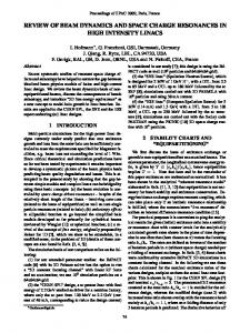
Figure 1: Sketch of the different longitudinal grids used in PATRIC for tracking, space charge, impedance kicks and parallelization. For the parallelization of the tracking step and the space charge calculation the bunch is divided into Nm ≤ Nb macro-slices, with slice center positions Zm and slice length ΔZ ≥ Δl. For efficient load-balancing the macroslice length is adjusted automatically to the bunch profile during a simulation run. Particles migrate slowly between macro-slices due to synchrotron motion. After each tracking step the particles are exchanged between neighboring macro-slices using MPI [8] routines. Each macro-slice keeps ΔZ/Δl 2D transverse grids and performs ΔZ/Δl serial 2D Poisson solver calls and bilinear grid-particle/particle-grid interpolations. The calculation of the transverse space charge field is greatly simplified if we use the approximation of rigid dipole oscillations. If we take the example of a parabolic beam profile the resulting electric space charge field is given through � 1 2 2 ¯) + y ) 2 − 2 ((x − x a (4) with the local current I(z) and the beam radius a. In this case the transverse grids are not needed. However, careful comparisons of stability boundaries obtained with selfconsistent space charge are required before the ’frozen’ space charge calculation can be used in the required 3D studies for the FAIR rings. I(z)(x − x ¯) Ex (x, y, z) ≈ 2 2π�0 v0 a
�
IMPEDANCE KICKS The ’dipole moment times current’ at a fixed ring position s is ψ(t).The resulting horizontal kick per turn (see e.g. [9]) is � F⊥ ds Δx�imp = 2 = (5) β0 E0
268
⎞ � iq ψj Z⊥ (Ωj ) exp(iΩj t)⎠ Re ⎝ β0 E0 j ⎛
with the frequency spectrum ψ(Ωj ) at the coherent dipole oscillation frequencies (bare machine tune Q) Ωj = (n ± Q)ω0
(6)
The horizontal dipole moment along the longitudinal particle position z is defined as
ψ(z, t) = β0 c xρ(x, y, z, t)dxdy (7) and the Fourier spectrum is ( ring circumference L)
L
ψ(z, t) exp(−inz/R)dz (8)
ψn (t) = exp(∓iQω0 t) 0
The amplitude ψn (t) varies slowly with time. For lumped impedances the resulting kick is applied every Δs Δx�imp (z, t) = � Re i exp(±iQω0 t)
�
Δs q × L β0 E0
(9)
ψn (t)Z⊥ [(n ± Q)ω0 ] exp(inz/R)
n
For a localized impedance source we set Δs = L and the kick is applied every turn. The numerical implementation of impedance kicks in PATRIC employs a grid along the z-axis with periodic boundary conditions at z = 0 and L. Let zj = jΔz be the grid points along the z-direction. For the transverse kick due to a localized impedance source we set Δs = L. The time between the kicks is then Δt = T and tk = kT . ψ(zj , tk ) is the dipole moment at the position zl and turn
Computer Modeling of High Current Effects Circular Accelerators
Proceedings of ICAP 2006, Chamonix, France
WEA3MP04
k. The horizontal kick is applied to all particles every turn using a Fast Fourier Transformation (FFT)
� q Δx� (zj , tk ) = Re FFT−1 [iψn (tk )Z⊥ ((n ± Q)ω0 )] β0 E0 (10) with the dipole amplitudes ψn (tk ) = FFT[ψ(zj , tk )]
(11)
VALIDATION AND APPLICATION EXAMPLES PATRIC is presently being validated against the available analytic examples. Here we discuss some of the more ’non-standard’ examples of 3D code validation using coasting beams. In the examples a simplified accelerator model with constant focusing and reduced ring circumference is chosen. Finally transverse stability studies in bunched beams are briefly discussed.
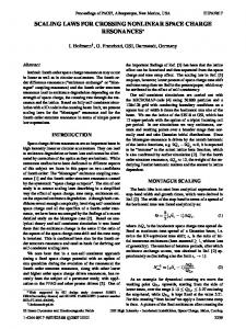
Figure 2: Noise power spectrum from the simulation.
Noise spectrum and stability boundary Transverse stability boundaries in long bunches depend critically on the longitudinal momentum spread and the associated Landau damping of coherent dipole modes. In a coasting, stable beam the transverse ’Schottky’ noise is one option to validate whether a 3D simulation code, like PATRIC, can correctly resolve this coupling effect. Because of the ’granularity’ of the computer beam, which is much coarser than in a real beam, the noise spectrum contains a wealth of information on incoherent and coherent effects, but also on artificial effects. Here we focus on the noise frequency spectrum of offset oscillations obtained from the Fourier transformation of the dipole current ψ(t). In the simulation example chromaticity is set to zero and the rms horizontal tune spread is Sx =| η(n ± Qx )ω0 δrms |
(12)
with the slip factor η, the bare tune Qx and the rms momentum spread δrms . The impedance spectrum used in the example has a large negative imaginary contribution ZI (e.g. due to wall image currents). The resulting coherent tune shift and the space charge induced incoherent tune shift are adjusted to the same value (−0.01 in the example). Under these conditions Landau damping is maximized. A broadband oscillator is added to the impedance spectrum Z⊥,r =
ZR ω ωr 1 − iQ (ω/ωr − ωr /ω)
(13)
with the resonance frequency ωr tuned to harmonic n = 10 of the simulation model. The value of ZR is chosen well below the instability threshold obtained from the analytic dispersion relation for a Gaussian momentum distribution. ˆ The resulting noise power spectrum | ψ(ω) | is shown in Fig.2. For harmonics close to n = 10 one can clearly observe the relative enhancement of the ’slow’ (n − Qx ) lines relative to the ’fast’ (n + Qx ) lines. In the examples
Computer Modeling of High Current Effects Circular Accelerators
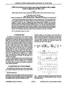
Figure 3: Comparison of the noise power spectrum for the slow mode close to (11−Q) (red dotted line) with a shifted Gaussian (blue dashed curve). the circumference is 54 m or one quarter of SIS 18. The bare tune for this reduced circumference is is Qx = 0.81. Details of the ’slow’ line at (11 − Qx ) are shown in Fig. 3. The location of (11 − Qx ) is indicated by the vertical red dotted line. The blue dashed curve is a Gaussian with rms width Sx with the frequency shift induced exactly by the imaginary impedance component. This ’Schottky test’ covers the incoherent (width of the line) and the coherent (shift of the line) beam properties relevant in beam stability studies. In Fig. 3 on can also observe that deviations from a Gaussian start at ≈ 2Sx . In the present example we used only 5 · 105 macro-particles. Using more particles will improve the resolution of the tails of the Gaussian. The simulation results shown were obtained with a frozen, linear space charge model. The comparison with the self-consistent space charge model and a homogenous transverse beam profile (K-V distribution) showed no significant difference in the noise power spectrum. As a second validation example the analytic stability boundary for a Gaussian momentum distribution [10] is checked. In the example we fix the space charge tune shift and vary the
269
WEA3MP04
Proceedings of ICAP 2006, Chamonix, France
Figure 4: Final (simulation time T ) dipole current amplitude ψ(t = T )/ψ(t = 0) from a simulation scan. The red dashed curve is the analytic stability boundary for a Gaussian momentum distribution. imaginary impedance ZI and the resonator impedance ZR . Fig. 4 shows the stability boundary in the (ZR , ZI ) plane obtained from such a parameter scan. Here the result of 100 simulation runs with different (ZR , ZI ) values is automatically analyzed and displayed using Python scripts. The color code represents the obtained maximum of the dipole current. The stable area (no growth) is indicated in blue. One can see that there is a rather good agreement around the center of the stable area. These validation studies are still ongoing. The parameter scan shown in Fig. 4 has been obtained using self-consistent space charge kicks and a initial K-V distribution, leading to a linear space charge field.
Stability boundary in bunched beams Besides the code validation activities 2D and 3D simulation studies with PATRIC focus on two important beam physics issues. Firstly the relevance of self-consistent space charge for transverse stability boundaries is being studied (see also Ref. [11]). With frozen space the simulation runs are faster and effects of numerical noise are minimized. The question is whether with frozen space charge one misses important instability damping or destabilization mechanisms. Secondly the transverse stability boundary in long bunches (long relatively to the resonant wavelength of the broadband oscillator) is being compared to the boundary for the corresponding coasting beam. In bunched beams the variation of the coherent and incoherent tune shifts along the bunch [12] as well the velocity of the unstable waves on a beam with finite extension are expected to increase the stability boundary. Fig. 5 shows a snapshot obtained from the simulation of the instability evolution in a beam confined between two rf barrier waves. The simulation parameters are the same as those used in the coasting beam studies in the the previous section. As
270
Figure 5: Evolution of a transverse instability in a beam that is confined between two rf barrier waves. a preliminary result we found that the stability boundary in long barrier buckets is only slightly enlarged compared to the equivalent coasting beam. However, extensive simulation studies using different beam parameters and also conventional rf buckets still have to be performed.
CONCLUSIONS The simulation tool PATRIC has been developed at GSI in order to study coherent instabilities in the presence of space charge in the FAIR synchrotrons. The recently implemented 2.5D space charge and transverse impedance kicks are still being validated against various analytic examples. Preliminary results indicate that for the required 3D stability studies, at least for first estimates, a ’frozen’ space charge model can be employed. Benchmarking with the HEADTAIL code [5] using FAIR and CERN PS/SPS parameters as well as experimental observation will be one of the important next steps.
REFERENCES [1] [2] [3] [4] [5] [6] [7] [8] [9] [10] [11] [12]
P. Spiller, Proc. of PAC 2005, p.294 B. Doliwa, Proc. of ICAP 2006, in print O. Boine-Frankenheim, Proc. of EPAC 2006, p. 1886 A. Shishlo, et al., Proc. of ICAP 2006, in print G. Rumolo, et al. Proc. of ICAP 2006, in print G. Rumolo, V.Vaccaro, E. Shaposhnikova, CERN-AB2005-088-RF (2005) MAD-X home page: http://mad.web.cern.ch/mad/ see e.g. http://www-unix.mcs.anl.gov/mpi/ V. Danilov et al., Proc. of PAC 2001, Chicago, USA , p. 1752 K.Y.Ng, AIP Conf. Proc. 773, 365 (2005) V. Kornilov, O. Boine-Frankenheim, I. Hofmann, Proc. of ICFA-HB2006, Japan, 2006 A. Fedotov, J. Wei, V. Danilov, Proc. of PAC 2003, p. 3032
Computer Modeling of High Current Effects Circular Accelerators