rate responsive cardiac pacemaker, implement it in VLSI. ... stimulate the heart and then repeat the process of detection and .... artificial pacing of the device.
ISSN: 2277-3754 ISO 9001:2008 Certified International Journal of Engineering and Innovative Technology (IJEIT) Volume 2, Issue 4, October 2012
Implementation of a Demand Mode Responsive Cardiac Pacemaker Manoj Kollam, Supraja Pranesh, Anitha Raghavendra Abstract— This paper is aimed to design a single chamber rate responsive cardiac pacemaker, implement it in VLSI. A state machine approach has been followed to achieve the desired purpose. The heart of the pacemaker system rests in the pulse generator which forms the major portion of the paper. It has been developed using VHDL and implemented in hardware using FPGA. In the FSM, first an input event is detected. Once this input is detected a timer is set for approximately 0.8 sec, which will be the time between heartbeats, thus giving us 72 heartbeats per minute. Once the timer expires we check to see if a new event is detected. If one is detected we repeat the process of detection and waiting. If one has not been received we need to stimulate the heart and then repeat the process of detection and waiting. The code has been optimized and modified for different pacemaker modes. Adequate effort has been put in for designing a sensing circuit from ECG and maintains the data like events occurred using data compression techniques. It closes with pacemaker testing for real life applications and scope for further work in the field.
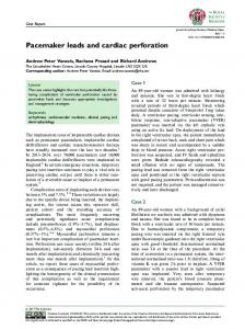
The sensing circuit performs the needed signal conditioning on the signals from the heart and processes them to convert into a form more acceptable to the pulse generator. It acts as an interface between the leads and the generator. II. BACKGROUND The following diagram shows a model of a basic single chamber pacemaker. This paper focuses on the timing engine of the pacemaker which controls when it paces and when it does not according to the patients need. In this case, the pacemaker timing engine is programmed by the physician through the physicians interface block, it receives notification of intrinsic events from the sense detection block, and it tells the pace pulse generation block when to pace. Heart
Index Terms— Pulse Generator, Timer, Timing Engine, VHDL.
RA
I. INTRODUCTION
RV
The pacemaker is a device implanted inside human body to correct improper functioning of the heart. It consists of three components: the pulse generator, the pacing leads, and the sensing circuit. The pulse generator contains the pacemaker’s power source and digital circuitry. A lithium/silver vanadium oxide battery having a 10yr shelf life is the main power source. The digital circuitry is bifurcated into a microcontroller that handles high-level control and manipulation, and a sequencer for handling routine pacing function. In this components are encompassed in the VHDL code written and dumped into the FPGA board which controls the execution of pacing considering the inputs from the other components of the device. The pulse generator receives its inputs as an electrical pulse through a sensing circuit from the heart, via electrodes or electrodes. The pulse generator senses the heart’s own electrical activity and responds according to the way it has been pre-programmed. Electrical stimulus from the pulse generator move through the pacing leads into the electrode tip. The leads for a pacemaker are used to stimulate the atrium or the ventricle on the right side of the heart. As such the leads perform the dual function of transmitting signals to and fro the pulse generator.
LA
Signal Conditioning
Amps/ Filters
Sense Detection
Pacemaker Timing Engine
LV
Physician Interface
Leads Pace Pulse Generation
Initial Focus
Fig 1. Basic single chamber pacemaker
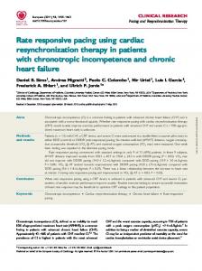
The Pacemaker Timing Engine operates as follows: If intrinsic contractions are not detected after a programmed interval (e.g. 1000 ms corresponding to 60 beats per minute), the pacemaker stimulates the heart with a pacing pulse. If intrinsic events are detected, the pacemaker inhibits (does nothing) for that cardiac cycle and restarts its timer for another programmed interval looking for intrinsic contractions. As a natural human heart has a refractory period where once an intrinsic event occurs, the heart will Most likely not contract again for a certain period (can be around 200 ms), thus this pacemaker will also ignore events that occur within a programmed interval of either a pace or sense.
113
ISSN: 2277-3754 ISO 9001:2008 Certified International Journal of Engineering and Innovative Technology (IJEIT) Volume 2, Issue 4, October 2012 electrocardiograms. Yet it is registered under certain special Ignored VSense conditions giving a hint about the improper working of the Skipped V Pace heart. The discussion of implication of each of the phases is beyond the scope of our discussion. A brief idea about the cycles would suffice our purpose. V Sense
Signals Seen on ventricular electrode V Pace
V Pace
V Pace
V. PULSE GENERATOR: THE HEART OF PACEMAKER
V Pace
Pacing intervals Refactory intervals Fig 2. Interval of Either A Pace or Sense
III. DESIGN OF A PACEMAKER ENGINE While our initial design will be for a simple single channel pacemaker (termed VVI for Ventricular Pacing, Ventricular Sensing and Inhibiting), my intent is to incrementally expand it to a channel pacemaker. This means that the design needs to follow a layered approach in order to manage complexity and to allow for future growth. The following diagram shows the internal architecture of the block at a very high level. Clock
Reset
VVI Pacemaker Engine
Base Interval
Vrefractory Block
ventricle pace request
refractory interval
ventricle event detection
Fig 3. The Internal Architecture of Pacemaker
The following sections break apart the design of the two blocks shown above and a general purpose timer that was used in both blocks. IV. CARDIAC CYCLE The pressure changes in the major blood vessels and the four chambers cause the valves to open and close and directly affect the flow of blood through the heart. The following phases of Atrial, ventricular, and aortic pressure take place over one cycle. They are: Atrial Systole Ventricular Systole Late Diastole Early Diastole The different phases of the cardiac cycle culminate in finally enabling the blood to be pumped throughout the body. Each part of the cycle has its special significance: some like the late diastole occurs non visible by most
Fig 4. Block Diagram of a Pulse Generator
The most important part of the pacemaker is the pulse generator (denoted as timing control in the diagram), and hence, the major portion of the project concentrates on this topic. The different kinds of pulse generators available and that has been designed in the due course of this project. Various constraints have been considered and a cumulative approach has been followed in designing the end result. A finite state machine is used to implement a simple demand pacemaker. A demand pacemaker is one in which there is no competition between the intrinsic pacing of the heart and the artificial pacing of the device. In other words, the pacer paces only in the absence of an R wave and so there is no competition between the two pacemakers. Depending on the number of chambers involved the number of states of the machine changes. A Mealy model of the machine has been used for the purpose. Depending on the present state and the current input (sensed intrinsic pace) the output and next state changes at every state. The basic process of pacing is described below. First an event is detected, in this case an R-wave. Once the R-wave is detected a timer is set for approximately 0.83 seconds, which will be the time between heartbeats, thus giving us 72 beats per minute. Once the timer expires it is checked to see if a new R-wave is detected. If yes, the process of detection and waiting is repeated. If no, the heart is stimulated then the process of detection and waiting is repeated. It was first done for a single chamber model (assuming pacing is needed just by the ventricles, atria functioning properly) and extend it to dual chamber (where both atria and ventricles are paced) Later the Rate Responsive pacemaker is designed considering a more practical design for the device. Finally the pacemaker is extended to different modes of working and results are observed.
114
ISSN: 2277-3754 ISO 9001:2008 Certified International Journal of Engineering and Innovative Technology (IJEIT) Volume 2, Issue 4, October 2012 Table 1: State Table of Single Chamber Pacemaker VI. SINGLE CHAMBER PACEMAKER A Single Chamber Pacemaker is one in which only one of the two chambers of the heart-atrium and ventricle is paced. Since there are, in total four chambers, we consider each side of the heart separately. As such, there are two chambers to be considered. Now, if in a pacemaker, one of the two is paced, it is called as a single chamber pacemaker. Usually it is the ventricles that are paced because they have stronger muscles and hence, a more powerful contraction owing to the fact that they have to pump the blood to a longer distance as compared to the atria.
V. PACEMAKER MODES
Fig 5. RTL Schematic of Single Chamber Pacemaker
Pacemakers pulse generators can be of various types depending on the modes of pacing. The human body has different requirements and those vary form one person to another. Accordingly the pacemaker used for one person cannot be generalized for all. Depending on the needs of the patient and the programmability options, the pacing pulse can be sensed as inhibited or triggered by the R wave of the ECG. Also there are competitive or non-competitive modes of pacing depending on if the intrinsic pacing of the heart is sensed by the pacemaker or not. Pacemakers can be: Demand: if the pacemaker senses the presence of an R wave and paces only if the R wave is not present. Non Demand: if the pacemaker paces the heart irrespective of the presence of an intrinsic R wave. Triggered: if the pacemaker paces the heart every time a R wave is detected i.e the pacing function is triggered by the R wave. Inhibited: if the pacemaker paces the heart every time a R wave is skipped i.e the pacing function inhibited by the R wave. As examples, the DDDR, VVI and DDI modes have been specifically programmed and results were observed. The following table shows the different working modes. Table 2: Pacemaker Modes
Fig 6. State Diagram of Single chamber pacemaker
State Diagram of Single chamber pacemaker State Table Inputs are: s: sensing parameter: 1 if contraction is sensed. z: timer output: 1 if timer reaches 0. Outputs: t: output to timer: 1 if timer is to be reset. p: output to heart : 1 if pacing needs to be done.
VI. VREFRACTORY BLOCK This block was separated into two elements: A controller ->VRefController A data path -> a timer.
115
ISSN: 2277-3754 ISO 9001:2008 Certified International Journal of Engineering and Innovative Technology (IJEIT) Volume 2, Issue 4, October 2012 The following diagram shows the basic structure and the state-machine of the controller. sense
refractory interval
sense detect
pace_request
reset reset controller
timer restart_timer timeout clock
pace_request/ restart timer
sense detect / restart timer, signal sense
sensing timeout
Signal Sense
Signal Pace
TRUE
Fig 9. Results of Top-Level Simulation
TRUE
waiting
Fig 7. State-Machine of the Controller
The controller was implemented using a combination of structural and behavioral VHDL with the idea of using Mux’s to implement the control logic for the state machine. VII. VVI PACEMAKER ENGINE The VVI Pacemaker Engine was broken into a similar structure to the V Refractory block discussed above. The only difference is the functionality and that the controller was implemented using the dataflow style with just combinational logic controlling the progression of the state machine. The timer is held in recirculation mode and merely reset on every paced and sensed event by the controller. As shown, this result in a three state state-machine with all unused states automatically transitioning to the reset state.
The simulation shows the following behavior: An initial pace occurs which starts a refractory period. 2 sense events occur and are ignored because they are in the refractory period. A 3rd sense outside the refractory causes the pacemaker to restart its timing cycle 3 more paces occur as no more sense events are injected.
pace_request base_interval
sense detect
start = ‘1’ controller
timer reset timeout clock
Fig 10. Timer Simulation vsense/ reset timer
timeout / reset timer signal pace_request
wait
Pacing
Reset
TRUE TRUE
Fig 8. VVIPacemaker Engine State-machine of the controller
VIII. SIMULATION RESULT Simulations were run using Xilinx’s ISE Webpac tool and all non-trivial blocks were tested separately. The following shows the results of the top-level simulation.
The simulation shows the following behavior: The timer starting to count from 0 to the timeout value. If start is held high, it just repeats. If start is not held high, it resets and stops at zero. If the timeout value is changed from 255 to the value less than the current count, the timer times out immediately. This is a safety feature. The following simulation result shows the tests conducted for the VVI controller. In the case of systems driven by timers, testing the controller separately is a great way to speed up the system. The test shows the system responding to
116
ISSN: 2277-3754 ISO 9001:2008 Certified International Journal of Engineering and Innovative Technology (IJEIT) Volume 2, Issue 4, October 2012 Saitta (Eds), Proceedings of the 16th European Conference on the vsense, vtimeout and reset inputs, while delivering the AI. IOS Press, Amsterdam, Pg 735-737. appropriate reset_timer and pace_request outputs. [7] Simonetta Dell’Orto, Paolo Valli, Enrico Maria Greco, Sensors for Rate Responsive Pacing,Indian Pacing and Electrophysiology Journal, pg 137-143. [8] John Perrins, Types of sensor for rate responsive pacemakers, pg 1-2 [9] A N Sulke, A Pipilis, R A Henderson, C A Bucknall, E Sowton, Comparison of the normal sinus node with Seven types of rate responsive pacemaker during everyday activity, pg 25-31.
Fig 11. Tests Conducted for the VVI Controller
For the final example, the following diagram shows the test results for the VRefController block.
[10] A. Qeliker, D. Alehan, N. Kursat Tokel, M. Koray Lenk and S Ozme, Initial experience with dual-sensor rate- responsive pacemakers in children, European Heart Journal (1996) 17,1251-1255, pg 2-4. [11] PACEMAKER System Specification, Copyright 2007 Boston Scientific, January 3, 2007, pg 7-9. [12] Umashankar Lakshmanadoss MD, Abrar Shah MD and James P Daubert MD, Telemonitoring of the Pacemaker, pg 137-139. [13] Peter Bradley, Ph.D, RF Integrated Circuits for Medical Implants, pg 12-15.
Fig 12. Tests Conducted For the VRefController block
IX. CONCLUSION AUTHOR’S PROFILE
The testing methodologies for the device were discussed and the more suitable method was verified. Finally the device was implemented in hardware and conclusions drawn from giving approximate inputs and observation of outputs. Minor errors were observed which were worked upon for reduction. X. ACKNOWLEDGMENT Gives us pleasure to thank each and every individual, who helped us in presenting this paper. We sincerely express our gratitude to Smt. S.R. Bhagyashree (ECE-HOD of ATME college of Engg.) and Dr. K.S Srinivasan (Principal of ATME college of Engg.) for their constant guidance, encouragement and valuable advice.
Manoj Kollam is an M Tech Scholar of Embedded system at VNR VJIET, Hyderabad, and Andhra Pradesh, India. He has earned his Bachelor’s Degree (B.E) in ECE in 2007 from REC, Chennai, Tamil Nadu, India. He is presently working as an Asst. professor in ATME college of Engg., Mysore, Karnataka, India. He has presented four papers in International conferences in the field of Embedded System, VLSI, and RTO’s. Mr. Manoj Kollam is a Life member of ISTE (Indian Society for Technical Education ). His research interests include Embedded Systems, RTO’s, and VLSI.
REFERENCES [1] LSI Implementation of a Demand mode Dual Chamber Responsive Cardiac Pacemaker 2012
Rate
[2] Frank Vahid, Digital Design, John Wiley & Sons, Pg 138-139, 2005.
Supraja Pranesh is an under going B.E student of ECE at ATME college of Engineering. Miss. Supraja Pranesh is a Life member of ISTE (Indian Society for Technical Education) and ISF (IETE student forum).her area of interest includes Embedded System and VLSI.
[3] Sandro A.P.Haddad, Richard P.M.Houben, Wouter A.Serdijn, The Evolution of Pacemakers, IEEE Engineering in Medicine and Biology Magazine, Pg 1-5, May-June 2006. [4] Dominique Mery, Neeraj Kumar Singh, Technical Report on Formal Development of Two-Electrode Cardiac Pacing System, Universit´e Henri Poincar´e Nancy 1, Pg 4-6, April 13 2010.
Anitha Raghavendra is an under going B.E student of ECE at ATME college of Engineering. Miss. Anitha Raghavendra is a Life member of ISTE (Indian Society for Technical Education) and ISF (IETE student forum).her area of interest includes Embedded System and VLSI.
[5] Surakha Palreddy, Embedded Pacemaker Design, Pg 2-5, 1995. [6] Peter Lucas, Ruud Kuipers Frederick Feith, A System for Pacemaker Treatment Advice, R.L´opez de M´antaras and L.
117