development time for extended applications. Our goal is to implement the JPEG decoder using our ODYSSEY. (Object-oriented Design and sYntheSiS of ...
Implementation of a JPEG Object-Oriented ASIP: A Case Study on a System-Level Design Methodology Naser MohammadZadeh
Morteza Najafvand
Shaahin Hessabi
Maziar Goudarzi
Department of Computer Engineering Sharif University of Technology Azadi Ave., Tehran, Iran PO Box: 11365-9517 Tel: +98-21-66164601, Fax: +98-21-66019246
{hessabi,gudarzi}@sharif.edu, {naser,najafvan}@ce.sharif.edu JPEG compression algorithm retains low spatial frequency components in an image and omits high spatial frequency components. JPEG compression works well with photographs, as well as images of naturalistic scenery, where the majority of image information is of low spatial frequency.
ABSTRACT In This paper, we present a JPEG decoder implemented in our ODYSSEY design methodology. We start with an objectoriented JPEG decoder model. The total operation from modeling to implementation is done automatically by our EDA tool-set in about 10 hours. The resultant system is a JPEG decoder ASIP whose hardware part is implemented on FPGA logic blocks and software part runs on a MicroBlaze processor. This ASIP can be extended by software routines to implement the motion JPEG or MPEG2 decoding algorithms. We implemented our system on ML402 FPGA-based prototype board. Experimental results show that our ASIP implementation is comparable to other approaches while our approach enables quick and easy development of an ASIP using our EDA tool-set and effectively reduces time-tomarket.
Due to ever increasing complexity of products, designs will require more flexibility and less development time. The JPEG algorithm is the base of many image (de)compression algorithms, including Motion-JPEG and MPEG2 [2] algorithms. JPEG functions can be used to implement MPEG2 and Motion-JPEG decompression algorithms. In other words, if you have a JPEG decoder with programmability feature, you can reduce design and development time for extended applications. Our goal is to implement the JPEG decoder using our ODYSSEY (Object-oriented Design and sYntheSiS of Embedded sYstems) design methodology [3] that suggests design and reuse of Application-Specific Instruction-set Processor (ASIP) while the embedded-system design starts from an Object-Oriented (OO) application. We make a JPEG decoder ASIP with our design tool and report and analyze the experimental results.
Categories and Subject Descriptors C.3 [Special-purpose and application-based systems]
General Terms Design
The remainder of this paper is structured as follows. In Section 2, we review different implementations of JPEG decoder and compare them with ours. In section 3, the ODYSSEY design methodology is concisely presented. In Section 4, we briefly introduce the JPEG decoding algorithm. We describe our design and implementation flow in Section 5. Section 6 contains the simulation and implementation results. Finally, we conclude in Section 7.
Keywords ASIP, ODYSSEY, JPEG, Embedded Systems.
1. INTRODUCTION JPEG [1] is short for Joint Photographic Experts Group, which is the original name of the committee that wrote the standard. The standard is designed to compress either grayscale or full-color still images by exploiting limitations of the human visual system, particularly the fact that small color changes are perceived less accurately than small changes in brightness. Therefore, if we were to analyze a JPEG compressed image, we would find that it would not be identical to the original image it is based on, even if the two images were to look identical to the human eye. In general,
2. RELATED RESEARCH The JPEG decoding algorithm is implemented by many companies and incorporations. The majority of these implementations are commercial, such as those from Apple Inc. [4], C-Cube Microsystems [5], Handmade Software [6], Xing Technology Corporation [7]. All of these commercial implementations are embedded into larger suite and moreover very little information regarding their internal design is available in public domain, and hence, we do not consider them in our comparisons.
Permission to make digital or hard copies of all or part of this work for personal or classroom use is granted without fee provided that copies are not made or distributed for profit or commercial advantage and that copies bear this notice and the full citation on the first page. To copy otherwise, or republish, to post on servers or to redistribute to lists, requires prior specific permission and/or a fee. GLSVLSI’07, March 11–13, 2007, Stresa-Lago Maggiore, Italy. Copyright 2007 ACM 978-1-59593-605-9/07/0003...$5.00.
Barco Company [8] has delivered a fully synchronous IP core for JPEG decoding algorithm. This IP core processes each pixel in 1 clock cycle. Another IP core is provided by ACTEL company [9]. This IP core supports YUV 4:2:0 and 4:2:2 formats. Design and
329
local Instruction Memory
Traditional
A::g() routine
Processor Core
B::h() routine
Data Memory OA1 Data for Object 1 of Class A
Virtual Address
OA2
OB1 Attributes inherited from A B-Specific Attributes Class A type
Physical Address
Object Management Unit (OMU)
A::f() Functional Unit (FU) i.e. f() method from class A
Data & Control Signals
network
B::f() FU B::g() FU
Data & Control Bus OO-ASIP
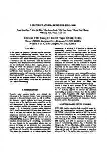
Figure1. Internal architecture of an OO-ASIP corresponding to a class A with f() and g() methods, and class B derived from A while redefining f() and g() and introducing h() method. hardware, and hence, programmable platforms not only reduce design risk, but also result in shorter time-to-market [13].
implementation of the hardware IP cores are done in low level so it is hard and time consuming. Lack of programmability is another difference, while our JPEG decoder ASIP is extendable by adding software methods to it with the aim of implementation of similar applications (such as MPEG2).
ODYSSEY synthesis methodology starts from an object-oriented model and provides algorithms to synthesize the model into an ASIP and the software running on it. The synthesized ASIP corresponds to the class library used in the object-oriented model, and hence, can serve other (and future) applications that use the same class library. This is an important advantage over other ASIP-based synthesis approaches since they merely consider a set of given applications and do not directly involve themselves with future ones. [14]
A multi-processor implementation of JPEG decoder is proposed by TU/e group [10]. They have used A|RT [11] tool suit to produce RTL-level HDL code. The A|RT tool is able to produce SystemC or VHDL RTL-level code for a VLIW machine from an algorithm-oriented, behavioral C code description. This work differs from our in our goal and approach, while we are to make an extendable object-oriented JPEG ASIP, they are not.
One key point in the ODYSSEY ASIP is the choice of the instruction-set: methods of the class library that is used in the embedded application constitute the ASIP instruction-set. The other key point is that each instruction can be dispatched either to a hardware unit (as any traditional processor) or to a software routine; consequently, an ASIP instruction is the quantum of hardware-software partitioning, and moreover, it shows that the ASIP internals consist of a traditional processor core (to execute software routines) along with a bunch of hardware units (to implement in-hardware instructions; see Figure 1).
3. ODYSSEY DESIGN METHODOLOGY Software accounts for 80% of the development cost in today embedded systems [12] and object-oriented design methodology is a well-established methodology for reuse and complexity management in the software design community. These facts motivated us to advocate and follow top-down design of embedded systems starting from an object-oriented embedded application. The OO methodology is inherently developed to support incremental evolution of applications by adding new features to (or updating) previous ones. Similarly, embedded systems generally follow an incremental evolution (as opposed to sudden revolution) paradigm since this is what the customers normally demand. Consequently, we believe that OO methodology is a suitable choice for modeling embedded applications, and hence, we follow this path in ODYSSEY.
An OO application consists of a class library, which defines the types of objects and the operations provided by them, along with some object instantiations and the sequence(s) of method calls among them. We implement methods of that class library as the ASIP instructions and realize the object instantiations and the sequence of method calls as the software running on the ASIP. A simple internal architecture for such an ASIP is presented in [3] and summarized in Section (3.1).
The other fundamental choice in ODYSSEY is the implementation style. ODYSSEY advocates programmable platform or ASIP-based approach, as opposed to full-custom or ASIC-based philosophy of design, since the design and manufacturing of full-custom chips in today 90nm technologies and beyond are so expensive and risky that increasing the production volume is inevitable to reduce the unit cost. Programmability, and hence programmable platforms, is one way to achieve higher volumes by enabling the same chip to be reused in several related applications, or different generations of the same product. Moreover, programming in software is a generally much easier task compared to designing and debugging working
3.1 ASIP Architecture A simple internal architecture of the OO-ASIP is shown in Figure 1. It corresponds to a library comprising two classes, A and B, where B is derived from A and has overridden its f() and g() methods and has introduced an h() method. The following C++like code excerpt demonstrates this. Note that redefinitions of the same method can reside in different partitions (e.g., A::g() is a software method while B::g() is a hardware one).
330
Where:
class A { void f(); void g(); …; // other member-functions and attributes }; class B extends A { void f(); // A::f() is overridden here void g(); // A::g() is overridden here void h(); ...; // other member-functions and attributes };
C (0) =
1, 2
C(k ) = 1 for1 ≤ k ≤ 7 s( y, x) = 2sample − D value S (v, u) = 2DCT − D coefficient
All objects data are stored in a central data memory accessible through an Object Management Unit (OMU). In the application corresponding to Figure 1, three objects are defined: OA1, OA2, and OB1. Objects of the same class (e.g., OA1 and OA2) have the same layout and size in memory for their attributes. Objects of a derived class keep the original layout for their inherited attributes (the white part of the memory portion of OB1) and append it with their newly introduced attributes (the gray part of OB1 box in Figure 1).
Compressed Image Data
The class methods that are assigned to hardware partition, i.e. the hardware methods, are implemented as Functional Units (FU); the other class methods, i.e. the software methods, are software routines stored in the local memory of the traditional processor core (the upper-left box inside the OO ASIP in Figure 1).
Variable Length Decoder Huffman Decoder
Run-Level Decoder
Inverse Quantization
Inverse DCT
F[v][u
Inverse Scan
f[y][x]
Quantization table
Design automation tools have been developed supporting the above-summarized ODYSSEY methodology [15].
QF[v][u]
QFS[n]
Reconstructed Image Data
Figure 2. JPEG Decoding steps [1]
5. OUR DESIGN and IMPLEMENTATION FLOW
4. JPEG DECODER Figure 2 shows key steps of JPEG decoding process. These steps can be summarized as follows:
Our JPEG model is an object-oriented model described in C++ and based on ISO 10918-1 standard (ITU-T Recommendation T.81); Our class library has three primary classes; The first one is “JPEGDecoder” which includes some JPEG decoding functions. The second one is “HUFFMAN” class which includes Huffman decoding main functions and the third class is “BLOCK” class including methods for manipulating the data blocks. We start with an object-oriented JPEG decoder model. The object-oriented code is synthesized by our ODYSSEY synthesizer. The resultant system from this process is a cosimulation model which can be simulated by Modelsim1 or run on Visual Studio. The software methods are in C++ and hardware methods in systemC. In this level, the software methods are run on a SystemC module that models the traditional processor. Figure 3 shows our design and implementation flow.
• Variable length decoding: This block decodes the variable length code that uses short words for most frequent values. This step includes Huffman decoding and run-length decoding process. • Inverse scan: This clause specifies the way in which the one-dimensional data, QFS[n], is converted into a two dimensional array of coefficients denoted by QF[v][u]. u and v both lie in the range 0 to 7. Two scan patterns are defined. The scan that shall be used is determined by alternate_scan which is encoded in the picture coding extension. • Inverse Quantization: The two-dimensional array of coefficients, QF[v][u], is inverse quantized to produce the reconstructed DCT coefficients. This process is essentially a multiplication by the quantizer step size. The quantizer step size is modified by two mechanisms; a weighting matrix is used to modify the step size within a block and a scale factor is used in order that the step size can be modified at the cost of only a few bits (as compared to encoding an entire new weighting matrix).
In the next step, the hardware methods2 are synthesized by Synopsys SystemC compiler and translated to VHDL. The software methods are compiled and placed in MicroBlaze instruction memory. In fact, the MicroBlaze processor substitutes processor module simulating processor in the high-level cosimulation model. At this level, system can be simulated by ModelSim or emulated by ML402 development board. [16]
• Inverse DCT: Once the DCT coefficients, F[v][u], are reconstructed, the inverse DCT transform shall be applied to obtain the inverse transformed values, f[y][x]. The defining equation for the 8x8 2-D inverse DCT is given by : C(v) 7 C(v) π (2x +1)u π (2x +1)v ∑ S(v, u)cos[ 16 ]cos[ 16 ] 0 ≤ x, y ≤ 7 v=0 2 u =0 2 7
s( y, x) = ∑
331
1
Modelsim 6.0 or later supports systemC.
2
We call hardware methods “functional units”.
JPEG Object-Oriented Model
is composed of onum (object number) and cid (class identifier). Figure 5 shows the address format for OMU.
BMP.bmp
System-level Synthesis
ODYSSEY Synthesizer
Class Identifier 4 bits
Cosimulation Model
Top Module in VHDL (the FUs Module )
EDK Preparator EDK Project Files (HDL Simulation and Synthesizable Codes)
Packet type 1 bit
Figure 3. our design and implementation flow The resultant JPEG ASIP synthesizable system is composed of four main parts: Processor, OMU, FUs and packet network. Figure 4 shows the system. PROCESSOR
(1-1-4)
OMU System Interface
Processor (MicroBlaze)
Figure 6. The control packet format Packet Network Interface
To invoke the packet-based method-dispatching mechanism in hardware- and software-methods, the ODYSSEY designautomation tools convert the virtual method calls in the input C++ program to the special routines of VMC_BY_HW(oid, mid) and VMC_BY_SW(oid, mid) respectively. Both functions take two parameters; the first parameter is the oid (object identifier) of the called object and the second one, mid, is the identifier of the called method. For methods that have one or more arguments, two other routines (namely, PARAMETERIZED_VMC_BY_HW(oid, mid, params, params len) and PARAMETERIZED_VMC_BY_SW(oid, mid, params, params len) are used instead. The params argument of these macros contains the method arguments whose length is given by the params_len argument. Two routines are implemented to handle accesses to objects data in our system: OBJECT_ATTR_WRITE that contacts the OMU to write a value to an attribute of an object, and OBJECT_ATTR_READ that sends read request to the OMU.
FU1 OMU Network FU2 Network Memory Mapper
Parameters 32 bits
OMU and Packet Network Models (including RAM)
Sender Object number 4 bits
Downstream Synthesis
Sender Method Identifier 6 bits
Main function of packet network is sending/receiving data and parameters to/from functional units. Any FU (hardware implemented method) can be attached to this network. The packet network width is 61 bits. Data and parameters are transferred in the form of packet. The packet format is shown in Figure 6. The packet-type field can have two possible values; 0 for METHOD_CALL and 1 for METHOD_DONE. When a FU wants to call another FU or a software method, it makes a METHOD_CALL packet type. After an FU or software method is done it sends a METHOD_DONE packet to the caller.
FUs in VHDL
Sender Class Identifier 4 bits
SW-Methods
The mapper part of OMU maps the virtual address generated by FUs or processor to physical address.
systemC Compiler
Main.cpp for Microblaze
Data index 24 bits
Figure 5. The OMU address format
FUs
Object number 4 bits
+
Object Number 4 bits
Method identifier 6 bits
Main() + Software Methods
Class identifier 4 bits
JPEG.jpg
FU2
Object Memory
Figure 4. The structure of our system The software part of our design is run on a MicroBlaze. The MicroBalze is a 32-bit RISC processor with 100 MHZ clock. The processor connects to OMU and packet networks through two FSL (fast simple link) peripherals [17].
To implement our system, we used Xilinx EDK 7.1 [18] embedded system development tool. EDK is a collection of software tools for designing embedded programmable systems, and supports designs of processor subsystems using the IBM PowerPC™ hard processor core and the Xilinx® MicroBlaze™ soft processor core. We used ISE 7.1i [19] for FPGA placement and routing. The system is implemented on ML402 FPGA-based prototype board, populated with a Xilinx Virtex-IV sx35 (FF668) FPGA [20]. Several peripheral devices and connectors serve as interfaces from the FPGA to external world.
OMU consists of OMU network, object memory, and mapper. The object data is stored in the OO-ASIP main memory. We call this memory “object memory”. The OMU network is responsible for synchronizing Processor and FUs access to objects’ data. The Processor or requesting FU provides the OMU with the address of requested data. The address consists of the oid of the object and the index of the data item within the object data storage. The oid
332
resource usage does not increase the implementation cost as long as the total area does not exceed the FPGA capacity, which is the case in this case study. Nevertheless, in general it is desired to reduce the resource usage so that either a smaller and less expensive FPGA can be used or more capacity is left for other functions to be implemented in the same FPGA. As mentioned, we are working on this.
6. SIMULATION and IMPLEMENTATION RESULTS We developed an OO program in C++ for JPEG decompression. Its validity was verified by decoding several JPEG files produced by various JPEG-compression programs as well as samples available from Independent JPEG Group [21] and JPEG official site [22]. It took less than 2 man-months to develop and debug this program from scratch. Then using our tool-set [15], it was converted to a hardware-software implementation in a matter of hours (see Table 2). Table 1 compares implementation factors of our generated hardware-software implementation with that of our original OO full-software one, Independent JPEG Group’s fullsoftware one, and a number of full-hardware implementations found in the literature. For all solutions with a software component, the processor used is MicroBlaze soft processor core implemented in logic blocks of Xilinx Virtex-IV sx35 (FF668) FPGA. The “#cycles” row shows the number of clock cycles required to decode a 32×32 pixels picture in 4:2:2 color format. The “Decompression time” shows the real time required to decode such a picture at the maximum clock frequency. The “Speedup” row compares performance of each implementation against full-software solution of Independent JPEG Group running on MicroBlaze with 100MHz clock frequency.
Obviously, we did not expect our results to be better in performance than full-hardware implementations. Our aim is to implement a programmable JPEG decoder ASIP in order to make system extendable and flexible. Consequently, although the area and speed of our implementation is expectedly lower than fullhardware ones, but the flexibility that it offers allows it to be reused for other related application, and moreover, the design time is significantly reduced since our approach only requires designing the missing functionality in software and adding it to the JPEG ASIP while the full-hardware implementation requires a very long time to design and develop working hardware. We indeed used this technique to extend our JPEG OO-ASIP to implement an MPEG2 decoder in just one month [23] while it normally takes several months to develop it from scratch. Table 2 summarizes simulation and synthesis results of our OO JPEG implementations. The synthesis is composed of two steps. The ODYSSEY synthesizer [15] step is the system-level synthesis operations and takes only a few seconds. The downstream synthesis step uses behavioral synthesis tools, FPGA P&R tools, and compilers to generate gate-level hardware and binary software; this step is very time-consuming, requiring about 10 hours to complete in the JPEG case. The simulation time row reports times for the three levels of simulation that are provided in our design flow: simulating the input OO program, simulating it after hardware-software partitioning but before elaborating each partition, and finally detailed gate-level simulation. The Execution Time row gives the number of clock cycles required to decompress a 32×32 pixels picture in our full-software and hardware-software implementations.
Table 1. Comparison of various implementations IJG Full-SW Programmable Logic Product Logic Device (gates) resource Memory usage (bits)
Our OO Full-SW
Xilinx Xilinx Virtex-IV Virtex-IV XC4VSX35 XC4VSX35
Our OO HW-SW
Actel Full-HW
Barco Full-HW
TU/e Full-HW
Xilinx Virtex-IV XC4VSX35
Actel Ax-1000
Xilinx Virtex-II XC2V1000
N/A
349799
349799
349799(CPU) +2113804
440000
786432
N/A
15500
16916
626688
36864
442368
N/A
Max. Frequency
100 MHz
100MHz
70MHz
52 MHz
41 MHz
40 MHz
#cycles
816 121
818134
367028
N/A
1024
20806 (4:1:1)
8.16
8.18
5.24
N/A
0.025
0.52
1
0.997
1.56
N/A
326
16
Decompression time (ms) Speedup
Table 2. Our JPEG OO-ASIP synthesis and simulation results Lines of C++ source code
As Table 1 shows, our full-software OO program is a little bit slower than IJG’s program. This reflects the impact of introducing OO concepts and constructs, which as a known fact is the price that one pays for the added flexibility and extensibility offered by object-orientation. However, our automatically-generated hardware-software implementation compensates that (see the fourth column of the table) and achieves 56% higher performance. This shows the effectiveness of the approach in improving performance by automatically implementing functionality moved to hardware.
Synthesis time
Simulation time
Execution (#cycles)
time
1700
ODYSSEY Synthesizer (s)
16.274
Downstream Synthesis (hour)
10
OO Full-software program (us)
925
HW-SW Co-simulation model (us)
98152
HDL co-simulation model (hour)
3
OO Full-software program
818134
HW-SW implementation
367028
As the results show, system implementation time from OO system model to FPGA bitstream is about 10 hours. To obtain complete system development time, the design-time of the OO JPEG program should also be considered of course.
Note that the higher resource usage of the hardware-software implementation is mainly due to the automatic synthesis of hardware components (using behavioral synthesis tools) from C++ software routines. This is indeed the known inherent problem with behavioral synthesis in spite of its merits in fullyautomatic top-down implementation flow. Addressing this issue, by investigating solutions to incorporate IP cores in the design flow, is part of our current research. Also note that when the target implementation platform is a given FPGA, the above
Table 3 shows implementation results of the ODYSSEYintroduced system functions. These are the OO concepts that our OO-ASIP architecture provides new implementations for. The second column of the table shows number of clock cycles elapsed for calling a virtual method in a full software implementation. The third column includes number of clock cycles needed to
333
availability of multi-million gate FPGAs, this is more likely to be the case as indeed is in this case study.
execute equivalent tasks in an OO-ASIP. Finally, last column shows the memory usage of the functions. Table 3. Implementation results of OO-ASIP Functions Delay Full Software (Clock Cycles)
Delay with OMU (Clock Cycles)
Memory Usage (bits)
VMC_BY_SW
26
75
156*32
PARAMETERIZED_VMC_BY_SW
29
80
158*32
VMC_BY_HW
N.A.
1
0
PARAMETERIZE_VMC_BY_HW
N.A.
1
0
OBJECT_ATTR_READ
6
31
13*32
OBJECT_ATTR_WRITE
5
36
13*32
Functions
ACKNOWLEDGMENT We would also like to thank A.M. Gharehbaghi for his insightful comments.
8. REFERENCES [1] Digital Compression and Coding of Continuoustone Still Images, Part 1, Requirements and Guidelines. ISO/IEC JTC1 Draft International Standard 10918-1, Nov. 1991. [2] ISO/IEC JTC1/SC29/WG11 N0702 Rev, "Information Technology – Generic Coding of Moving Pictures and Associated Audio, Recommendation H.262", Draft International Standard, Paris, 25 March 1994. [3] M. Goudarzi, S. Hessabi, A. Mycroft, "Object-Oriented Embedded System Development Based on Synthesis and Reuse of OO-ASIPs", Journal of Universal Computer Science, Vol. 10, No. 9, PP. 123-135. [4] Apple Inc., www.apple.com [5] www.storagesearch.com/ccube.html [6] Handmade Software Company, www.handmadesw.com. [7] Xing Technology Corporation, www.yu-xing.com. [8] Barco Company, http://www.barco.com/ [9] Actel Company, http://www.4i2i.com/ [10] S. Stuijk, “Design and Implementation of a JPEG Decoder”, Practical Training Report, www.es.ele.tue.nl , December 2001. [11] AR|T,http://www.adelantetech.com/ [12] International Technology Roadmap for Semiconductors, (ITRS), 2003, http://public.itrs.net/ [13] K. Keutzer, S. Malik, A.R. Newton, “From ASIC to ASIP: the Next Design Discontinuity,” Proc. of Int’l Conference on Computer Design (ICCD’02), 2002. [14] Benini, De Micheli. “Networks on chips: a new soc paradigm”. IEEE Computer, Vol. 35, No.1, Jan. 2002 pp. 70-8 [15] N. MohammadZadeh, S. Hessabi, M. Goudarzi, “The ODYSSEY tool-set for system-level synthesis of objectoriented models. Embedded Computer Systems: Architectures, MOdeling, and Simulation (SAMOS),” Springer-Verlag LNCS 3553, July 2005, pp. 394-403. [16] Boards, http://xilinx.com/products [17] Microblaze Processor, http://www.xilinx.com/products, [18] Embedded development kit, july 2005, www.xilinx.com. [19] ISE Foundation, http://www.xilinx.com/products, [20] Virtex series, http://www.xilinx.com/products/silicon_solutions/fpgas/virtex [21] Independent JPEG Group web-page, http://www.ijg.org/ [22] The official site of the Joint Photographic Ex-perts Group, JPEG, http://www.jpeg.org/ [23] N. MohammadZadeh, S. Hessabi, M. Goudarzi,, "Software Implementation of MPEG2 Decoder on an ASIP JPEG Processor," Proc. of International Conference on Microelectronics (ICM'05), P.P. 310-315, Islamabad, Pakistan, 13-15 December 2005.
Note that while the above area and time figures show that our JPEG OO-ASIP implementation is even 56% faster than fullsoftware implementation, this speedup is not its real advantage. The main advantage of our ODYSSEY methodology and its implementation as an OO-ASIP is the extensibility through software that is provided for future extending applications. We showed one such extension in case of a JPEG decoder OO-ASIP being extended to an MPEG2 decoder one in [23]. Detailed implementation results of the case study presented in this paper brings us to the conclusion that the ODYSSEY technique for “hardware evolution by software” does not impose unacceptable overheads while it provides the flexibility and design speed offered by software.
7. CONCLUSIONS In this paper, we presented a case study on ODYSSEY, an objectoriented system-level design methodology, by implementing a JPEG decoder in the ODYSSEY design style. This results in dramatically reducing time-to-market when developing new applications that are extensions of previous ones. The design automation tools that we have developed corresponding to ODYSSEY methodology further reduce time-to-market and ease the design process. Experimental results of this case study show that although performance is not the main focus in the ODYSSEY design methodology, its implementation approach does not result in unacceptable performance overheads while its ASIP approach decreases design time due to programmability, and its OO basis brings OO advantages, such as flexibility and extensibility of design, to the hardware world. The expected lower performance compared to full-hardware implementations is compensated by the increase in flexibility and effective reduction in time-tomarket. This case study also showed us that further improvement of the performance and area figures helps in strengthening the advantages of the methodology and the OO-ASIP architecture specially if implemented as a custom chip. This is part of our current research, specifically investigating ways for incorporating pre-designed IP cores instead of top-down behavioral synthesis for some functional units. It is, however, noteworthy that the fully top-down procedure employed in this case study, and the behavioral synthesis in particular, can still be cost-effective as long as the target platform is an FPGA and the given FPGA has sufficient capacity. With the current trend toward programmable platforms in very deep submicron technologies [13] and
334