Implementation of a path planner to improve the usability of a robot dedicated to severely disabled people M. Mokhtari 1, 2 B. Abdulrazak1, 2, R. Rodriguez 1, B. Grandjean2 1
HANDICOM Lab, Institut National des Télécomunications (INT), Evry, France. 2 INSERM-U483, University Pierre & Marie Curie, Paris, France. Email :
[email protected]
Abstract -The design of robot dedicated to person with disabilities necessitate users implication in all steps of product development: design solution, prototyping the system, choice of users interfaces, and testing it with users in real conditions. However, before any design of any system, it is necessary to understand and meet the needs of the disabled users. In this paper, we describe our research activity on the integration of a robotic arm in the environment of disabled people who have lost the abilities to use their proper arms to perform daily living tasks and who are able to use an adapted robot to compensate, even partly, the problems of manipulation of objects in their environments. This paper presents our contribution for designing adaptable, configurable and personalized robot system based on the Manus robot. Some preliminary evaluation results are also presented.
1. INTRODUCTION People who have lost the capabilities to use their proper arms to perform daily living task could use an adapted robot to compensate, even partly, the problems of object manipulation generated by their handicap. Several robotized systems have been performed this last decade to help people with severe motor disability. Many developments in the rehabilitation robotics field have lead to some encouraging robotic arms. They were developed to offer more independence to persons with severe disabilities and to perform tasks in their daily lives. The Manus arm is one of these robotic devices. The scientific community in this field has been divided into two groups: the ones which thinks that the robotized system should be fully automated to perform complex tasks in an autonomous way without having the user in the control loop, and the ones which defend the idea of having the user in the command loop of the robot. The development done in the former case consisted on robotized workstations which have the advantages to perform task in an optimized way in term of trajectory and in term of time, but with the condition of having a structured environment which has been modeled. In the latter case, the research activity investigated the robotic arm, mounted on wheelchair or mobile base and controlled manually by the user. The main advantage of these systems is the possibility to perform task in an open and changing environment, but the optimization of the movement is based on the motivation of each user. Our team belongs mainly to the second group and in this paper we describe the current
development in this field, which are supported by the European commission with the Commanus1 project and the results obtained during the evaluation process. A new evaluation method, based on a quantitative analysis, has been developed to estimate exactly the usability of the system.
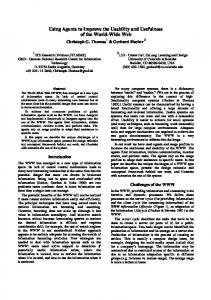
2. THE MANUS ROBOT MANUS is a robot mounted on an electrical wheelchair (Fig 1). It is aimed to favor the independence of severally handicapped people who have lost their upper and lower limbs mobility, by increasing the potential activity and by compensating the prehension motor incapabilities. Manus is a robot with six degrees of freedom, with a gripper in the extremity of the arm which permits the capturing of objects (payload of 1,5 kg) in all directions, and a display. It is controlled by a 4x4 buttons keypad or by a joystick, and with the latest version, a mouse and a touch screen control was provided. A display unit gives the user current status of the MANUS.
Fig. 1 The Manus robot used in a supermarket
3. SOFTWARE COMMAND ARCHITECTURE The Manus software architecture allows us to choose many modes in order to offer several possibilities of controlling the arm [12]. As shown in figure 2, the basic software 1 COMMANUS project, EC DGXII Biomed-Craft program. Partners involved: Exact dynamics, TNO-TPD and RTD-HetDorp in the Netherlands, Oxime in UK,and INT, INSERM, AFM and A6R in France
architecture, called Manus modes, has three different control modes: The Cartesian Mode, which allows the user to control manually the arm and gripper motion in Cartesian space, the Joint Mode which allows a direct and separate control of the six arm joints, and the Main Mode which allows access to the above cited modes and allows the user to perform specific commands such us fold-in, fold-out, drink....
eating or drinking with the Manus. This is natural for human movement, but heavy when using a robot The strategy we have followed was to try to identify the repetitive movements and implement them as automatic gestures available for the user. A gesture library was integrated in the software architecture and a path planner was developed to allow point-to-point and pointing-and-doing modes.
Regarding the evaluation results, we have developed new command architecture, called Commanus modes, and implemented several extra modes beside the Manus modes to meet the users needs. Four new control modes have been developed and integrated to the software architecture of Manus robot.
4. IMPLEMENTATION OF A PATH PLANNER
Figure 2 : Commanus command architecture
The first additional mode is called « Record & Replay Mode » which allows the user to record specific positions and movements, and when it is required to reach them later, only an automatic movement generated according to the recorded point will be required. When the gripper is in a specific position in a given space and a given configuration, the user will be able to record the coordinates of the point to be able to return directly to this point any time using only one action on the input device [4]. The second one is the “Pilot mode” which allow to handle Manus robot in the direction of the gripper following the main axis. This mode has been developed mainly when using a 2D joystick to control the robot when practicing robot forward action in the direction of the target, which is similar to the human approaching movement to grip an object. The third mode is the Relative mode which allow movements of the gripper, usually where it is near the target, to perform small defined steps relatively to the target position and to the current position and orientation of the gripper. This mode is useful during task requiring high accuracy, such as inserting a video tape in the VCR. During evaluation, we have noticed that, even with this modes, the user have to perform the same sequence of command action when processing repetitive tasks, such as
A. Gesture library In the human physiology, any complete natural gesture is describe as being two-phased: an initial phase that transports the limb quickly towards the target location and a second long phase of controlled adjustment that allow to reach the target accurately. Those two phases are defined respectively as a transport component and a grasp component [8]. Each component is a spatio-temporal transformation between an initial state, and a final state of the arm. In our approach, we are interested in automating the first phase describe above. The second one require sensors (such as cameras and effort sensors) that are, from a conceptual point of view, impossible to be realised on the Manus. The gesture library contains a set of generic global gestures that help disabled people to perform complex daily tasks. These gestures correspond to only a portion of any particular task. As shown below (Fig.3), each gesture (Gi) is characterised by an initial operational variable of the robot workspace (Oii) corresponding to the initial robot arm configuration, and a final operational variable (Oif) corresponding to the final robot arm configuration.
Oi (xi, yi, zi, yawi, pitchi, rolli)
Of (xf, yf, zf, yawf, pitchf, rollf)
End-effector trajectory
Figure 3: Robot configurations characterising a gesture
Each variable (Oi) is defined in the Cartesian space by the gripper position (xi, yi, zi) and orientation (yawi, pitchi, rolli). The gestures generated by our system are linked only to the final operational variables. The path planner is able, from any initial arm configuration, to generate the appropriate trajectory to reach the final configurations.
We have pre-recorded twelve final operational variables which allow the user to record two others (Fig.4).
avoidance algorithm based 3D geometrical calculation [2][3] [10][11]. The path planner integrates the intermediate points when calculating an automatic gesture as defined above. Consequently, the control of the arm should be simplified for the user and this will offer gain in term of time and of control efficiency. Actually, the 3D virtual boxes are statically defined to validate path planner functionalities. A dynamic definition of forbidden area is currently under design to allow the user defining obstacles according to his own changing environment. This concept is complementary to the co-autonomy concept, described below, where, in case of a non defined obstacle, the user should always have the ability to modify the trajectory generated by the planner trajectory.
5. TOWARDS THE CO-AUTONOMY CONCEPT Figure 4: Point-to-Point control mode
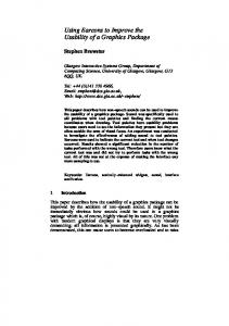
B. Obstacles avoidance To improve the point-to-point mode which perform movement in blind way without taking into account environmental obstacles, we have decided to design a new strategy based on the dynamic generation of 3D obstacle. One example of commonly performed task with the Manus is gripping a glass from a table as shown in figure 5.
The co-autonomy concept was recently introduced as a promising way to design assistive robots intended to meet the needs of disabled people[1]. This concept is based on the control charring between the human and the assistive robot. This approach was also proposed for obstacle avoidance in tele-robotic systems applications in hazardous environments [6]. Three types of situations were mentioned to define the coautonomy concept. 1. 2. 3.
Figure 5 : Path planning process avoiding obstacle
The path planner takes into account obstacles located inside the working space of the robot between the initial and final configuration of the arm. Physical obstacles are virtually encapsulated in boxes playing the role of forbidden areas. In this case a first box represents the arm column which could not be crossed during the movement, and a second box representing the table obstacle. Intermediates points defining the robot trajectory are generated by the use of a developed
the user is in total control. the machine is in total control. The user and the machine share the control.
The software command architecture is designed to fit this co-autonomy concept. In the first version of the command architecture, the first and the third type of the situations cited above can occur. Users are in total control when they are using the Cartesian Mode and share the control with an autonomous controller when they are using the Point-toPoint Mode. As describe in [4] the gesture in the Point-toPoint mode is controlled by the user by pressing, for example, the keypad button continuously until completion. The gesture stops if the button is released or continues otherwise (We can qualify such control as a pseudo-sharing control). This was designed to prevent collisions with the user, other persons, or obstacles. Pressing a button of a keypad or pushing a stick of a joystick until completion of the gesture may sometimes be exhausting for some users with severe disability. To prevent from this fatigue, we thought to include the second type of situation of the co-autonomy concept in the command architecture and integrate the user in the autonomous control
loop, ie. allowing him/her to intervene during the automated gestures. The user may then, during the progression of the arm towards the target, make gripper position adjustments. For example, it could occur that the path planner generates a trajectory that would go throw an obstacle. In this case, a collision of the arm with the obstacle will happen. The user may then, act on the input device to ovoid this collision. Such a situation may be done, as shown in Figure 5, in three phases. An automatic phase, where the end-effector follows the trajectory processed by the path planner, a semiautomatic phase where the user intervenes to avoid the obstacle, and finally, another automatic phase, when the user stop intervening, and where a new trajectory towards the target is generated. Such control mode that we have called Pointing-and-Doing Control Mode which will complement the Point-to-Point Mode. As shown in figure 6, the task is performed following different phases : End of the gesture
Of
Obstacle The user start controlling
3rd Phase 2nd The user stop controlling 1st phase
Oi
The user select the gesture Figure 6: Pointing-and-Doing mode
1st phase: autonomous phase The end-effector follows the trajectory processed by the path planner 2nd phase: semi-autonomous phase The user intervenes during the autonomous phase to avoid the obstacle. 3rd phase: autonomous phase The user stop intervening: A new trajectory towards the target is generated.
6. QUANTITATIVE USERS NEEDS ANALYSIS A. Methodology The aim was to develop original methods based on quantitative evaluation to analyze accurate data on the usability of the Manus robot and particularly the contribution of the new added modes. The idea was to record all the actions performed by the users on the input devices. The log file generated contains each command executed by user on device, the execution time of the robot, the corresponding mode, the robot gripper joint and position coordinates, and some other data. This method allow to see which time the user spends in each mode, how many actions he makes in each mode, and how many warnings and error messages has been generated. The evaluation process is decomposed on tow phases: The learning phase and the evaluation phase of Manus to perform some specific tasks. During the learning phase, which could last from 10 minutes to an hours depending on the users; the users learn how to control Manus, how to use input device functionalities and how to swap between different control modes described above. Below we present the results which correspond to eight months of evaluation recording with quadriplegic patient, mainly having spinal cord injuries and muscular dystrophies, at the rehabilitation hospital of Garches where our team installed an evaluation site. The preliminary results presented correspond to eleven users from fifteen: Eight patients used a 3D joystick to control the Manus, and six users used a 16 buttons Keypad, and one person used a mouse scanning device. These eight months of recordings, mainly dedicated to the Commanus version, correspond to more than 37 hours of effective use Manus robot in institution. Evaluation outside the hospital and at homes of disabled people have been also performed, but with the Manus commercialized version of the robot [7]. B. Preliminary results The first graph (Fig. 7) shows the time repartition during the whole evaluation duration (134.360.392ms =37 hours an 17 minutes):
Mode (Nb actions)
Mode (Execution Tim e)
Pilot (15,0%) Cartesian relative (4,1%) Cartesian position (3,4%)
Joint relative 234 227,00 Cartesian relative 868 100,00 Joint position
2 479 878,00
Pilot
3 124 476,00
Cartesian position
3 497 029,00
Joint velocity
5 142 332,00
Joint velocity (23,7%) Cartesian velocity (51,9%) Joint position (0,8%) Joint relative (1,1%)
10 837 469,00
Cartesian velocity
108 176 881,00
NOP
Fig. 7 Time repartition for control modes
The “NOP” time (no actions or rest time) is considerable and represents 80,5% of the total duration of the evaluation. But we have to make the distinction between four types of rest times: -
A no action time: when the user takes a real rest without switching off the Manus; A cognitive time: when the user is thinking on the sequence of action he plans; A physiological motor time: the physiological time necessary to execute a movement with hand or finger.
The “Cartesian velocity mode”, corresponding to the Cartesian Mode, is the most frequently used (8,1% in time) and could be processed with three different speeds: slow, medium and high speed. As shown in figure 8, the Cartesian velocity mode speed medium (2) is the most frequently used (53% in time) where the “Cartesian mode” in high speed (3) is not really used (1,2%), only when users want to do large movement of the arm robot. When a user wants to perform complex tasks, or when the gripper is close to the target, he usually chooses the “Cartesian mode” in low speed. Cartesian m ode speed level
Fig. 9 number of action repartition for control modes
Users manipulation on the input device generated 633 events without any robot activity (keypad buttons or joystick event without function). The Robot generated 92 warnings messages (robot in deadlocking configuration, limit of working space reached …). To recover deadlocking configuration, the user have recourse to the joint mode to ovoid restarting the system. During the evaluation users had to perform the same tasks, and to follow the same scenarios. Different parts have been performed according to the different control modes: P-01: part using the basic modes (Cartesian and Joint) P-02: P-01+Pilot mode P-03: P-01+Point to point mode P-04: P-01+Relative mode P-09: free scenario (all modes) Figure 10 shows parts repartition to some expert users (U0i) to perform the all the tasks: User / Part U-01 P-01 P-02 U-02 P-03 U-09 P-04 U-14 P-09 U-15
3544 4637 3328 3179 5044
3 (1,2%)
Fig. 10 Users-parts of scenarios repartition 2 (45,8%) 1 (53,0%)
Fig. 8 Cartesian velocity speed repartition
The representation in term of events or actions performed on the input device is shown below (Fig. 9). The whole recordings time correspond to 9715 Events actions sent to the robot
We remark that within the P-02 and P-03 the users needed less number of actions, which means that the Pilot Mode and the Point-to-Point mode contribute in the reduction of the number of actions and then to the reduction of execution time.
7. CONCLUSION In this paper we have tried to describe our design approach of an adaptable control system for Manus robot. The new architecture is designed to meet the disabled user needs in term of manipulation of the assistive robot Manus. these development are based on preliminary results obtained
from quantitative and qualitative evaluation with the participation of disabled people [9]. This system is designed on one hand, to reduce manipulation problems that disabled users meet during complex tasks, and on the other hand, to solve the problems linked to the user-interface. With its new functions, we plan to reduce the task time and the number of commands necessary for complex task. For example, the task serve and drink a cup of water using Manus, and a keypad as an input device, takes about 5minutes and requires about 180 commands. As it was noticed in [7], the users spend more than 50% of the task duration seeking for the good strategies to reach the target or seeking for the appropriate button. The interest of the gesture library is to cop with these problems and propose a more intuitive control. For example, one command in the Point-to-Point mode is sufficient to perform the same results than 10 necessary commands with the Cartesian Mode. The evaluation of the new architecture allowed us to bring some improvement to the system. The first trials with disabled patients showed their interest regarding the new added modes. The result obtained, are only preliminary results, and we can not yet pronounce on the real contribution of the new command architecture modes in the daily use of Manus at home and outside. More evaluations in real life conditions with the help of disabled people are necessary to test all the new functions offered by the proposed new system. The actual development realised during this project leaded to a new software architecture for Manus which was integrated through the European Commanus project which has ended this year. The continuation of this research work will be insured through the AMOR1 project which will start soon with the support of the European Commission. The aim is to propose a new generation of Manus robot taking into account the users requirements.
8. ACKNOWLEDGMENTS The authors would like to thank the people who have participated actively in this presented research work, particularly J.P. Souteyrand from INSERM U.483 for graphical design, C. Dumas, ergotherapist, from the rehabilitation hospital of Garches, and C. Rose from the AFM (French Muscular dystrophies Association) for his support and for providing us two Manus robots. 1 AMOR project EEC Growth program: Mechatronic upgrade & wheelchair integration of the Manus Arm manipulator. Partners involved: Exact dynamics, TNO-TPD and Koningh in the Netherlands, Ideasis and ExpertCam in Greece, Lund University in Sweden, HMC in Belgium, and INT and AFM in France
9. REFERENCES [1] Chatila R., P. Moutarlier, N. Vigouroux, “Robotics for the Impaired and Elderly Persons”, IARP Workshop on Medical Robots. Vienna, Austria. 1-2 Oct 1996. [2] Coiffet P., «La Robotique, Principes et Applications», Ed. Hermes, Paris, 1992 [3] Coiffet P., «La Robotique, Principes et Applications», Ed. Hermes, Paris, 1992 [4] Didi N, Mokhtari M., Roby-Brami A., « preprogrammed gestures for robotic manipulators : An alternative to speed up task execution using Manus », In Proc. ICORR’99 , Palo alto, California, July 1999 [5] Dombre E., Khalil W., «Modélisation et Commande des Robots», Ed. Hermes, Paris, 1988 [6] Guo C., T.J Tarn, N. Xi, A.K Bejczy," Fusion of Human and Machine Intelligence for Telerobotic systems", the IEEE International Conference on Robotics and Automation., Nagoya, Japan, May 1995 [7] Heidmann J, Mokhtari M., Méthode d’évaluation quantitative et qualitative appliquée au développement d’une aide technique robotique pour la compensation du handicap moteur. Ed. Euopia Paris, RIHM (Revue d’Interaction Homme-Machine). Vol. 3, n°1, May 2002. P79-99. [8] Jannerod M., “Intersegmental coordination during reaching at natural visual object”. In J. Long & A. Baddeley (Eds.) Attention and performance IX, P153-169, Hillsdale, NJ: Lawrence Erlbaum Associates [9] Mokhtari M., Didi N., Roby-Brami A., « A multidisciplinary approach in evaluating and facilitating the use of the Manus robot. IEEE-ICRA’99, Detroit, Michigan. May 1999. [10] Pruski A., «Robotique Générale», Ed. Marketing, Collection Ellipses, Paris, 1988 [11] Pruski A., «Robotique Mobile, La Planification de Trajectoire», Ed. Hermes, Paris, 1996 [12] Vertut J., Coiffet.P., «Les Robots ». Tome 3a : Téléopération, Evaluation des technologies. Ed. Hermes. Paris, 1984.