is the name of the Java class which contains the code, followed by .... after its execution environment expires. More .... Domain Name System (DNS), wherein the.
Implementation of a Prototype Active Network A. B. Kulkarni, G. J. Minden, R. Hill, Y. Wijata, A. Gopinath, S. Sheth, F. Wahhab, H. Pindi and A. Nagarajan, Department of Electrical Engineering and Computer Science University of Kansas, Lawrence KS 66045
Abstract Active Networks carry SmartPackets which contain both data and user-specified methods to extend the functionality of switches to perform user-specific computation on the encapsulated data. This enables rapid customization of the network and provides a mechanism to adapt the network to a changing environment. In this paper, we describe the implementation of a prototype Active Network which is implemented in Java. We also illustrate the use of Active Networks to provide enhanced services at both the network and application levels.
1. Introduction Intermediate switches and routers in current packet switched networks are closed, vertically integrated systems whose functions are determined through a long standardization process and are rigidly built into the embedded software. Their functions are rigidly built into the embedded software. Active Networking [1][2] offers a different paradigm that enables programming intermediate nodes in the network. In an earlier paper [3], we defined a network to be active if it allows applications to inject customized programs into the network to modify the behavior of the network nodes. This allows applications to customize the network processing and adapt it to the application’s immediate requirements. This enables new protocols and new services to be introduced into the network without the need for network-wide standardization. To better understand the strengths and limitations of Active Networking, we †
This research is partially funded by the Defense Advanced Research Agency (DARPA) under contract F19628-95-C-0215.
developed an prototype implementation of an Active Network in which program code and data is placed inside specialized packets called as SmartPackets. When a SmartPacket reaches an Active Node, the code inside the SmartPacket is extracted and executed. Depending on the nature of the code inside the SmartPacket, the SmartPacket either modifies the behavior of the Active Node or transforms the data it is carrying. In this paper, we describe a format for SmartPackets and an architectural model of an Active Node. This paper is organized as follows. We first describe the system architecture and its implementation. We then demonstrate how SmartPackets can be used to provide enhanced services by developing and introducing new network-level and application protocols into the network. This is followed by a presentation of some results that we obtained by measuring the performance of the system. We finally look at related ongoing research and give our conclusions and suggestions.
2. System Architecture To examine the properties and determine significant technical challenges of Active Networking, we chose to implement a prototype in JavaTM [4]. The Java Virtual Machine environment supports machineindependent programs and the language is quickly becoming a standard for objectoriented programs that can be compiled into an executable format and yet be exchanged between different platforms. We opted to implement the system using version 1.1 of the Java Development Kit (JDK) for two principal reasons: (1) it supports object serialization which allows us to transport state across the network in SmartPackets, and (2) this version is expected to be forwardcompatible with future versions as opposed to version 1.0.2.
1
Figure 1. An Example Virtual Active Network Topology
2.1 Active Nodes The virtual Active Network (Figure 1) is a collection of individual Active Nodes and a single Information Server each running on a separate Java Virtual Machine (JVM). Multiple JVMs may be run on the same physical host. The virtual links are simulated with TCP connections across sockets. The virtual network is maintained by the Information Server. At startup, nodes in the virtual network contact the Information Server to determine adjacent nodes they should connect to in the virtual network. Name Length TypeID of Class of Class
Class Definition
Length of Object
Serialized Object
Figure 2. On-The-Wire Format of SmartPacket
2.2 SmartPackets As mentioned earlier, the code and the data carried by the SmartPacket is in bytecode format. The code of the SmartPacket is actually a Java class which describes the methods that act on the user data. An instance of this class (which contains the user data) is sent in the SmartPacket as a serialized object along with the bytecodes which comprise the class definition. At an Active Node, the class definition is used to define the class to the execution environment and then the object is de-serialized to recover the class instance. The instance is then executed in a thread of its own. The format
of a SmartPacket is shown in Figure 2. The first 128 bits represent a TypeID, which is used to de-multiplex the SmartPacket to its correct processing environment. The next field is the name of the Java class which contains the code, followed by the number of bytes n representing the class definition. The actual class definition is followed by the length of the serialized object and then the serialized object itself. The TypeID is actually a hash of the description of the canonical structure of the SmartPacket. The idea is that any composer of a SmartPacket (user, application, router etc.) wanting to define a new type sends the SmartPacket definition to a local Type Authority. This Type Authority authenticates the composer, checks the structure of the SmartPacket and converts the SmartPacket definition to canonical form. The canonical form is then hashed (using a standard hash algorithm) into a 128 bit number which is returned as the TypeID of the SmartPacket.
3. Active Node Architecture The model of an Active Node is shown in Figure 3. Each node in the network is controlled by an Node Manager. The Node Manager is responsible for starting all of the other management objects, including the Port Manager, Resource Manager, Routing Manager, and Small State Manager. These managers are assigned the task of managing ports, node resources, routing, and small state, respectively. 2
Node Manager Port Manager
SmartPacket
Routing Manager
Data
Small State Manager
Resource Manager
Threads executing code in SmartPackets
Control
Small State
System Resources
Figure 3. Model of Active Node
3.1 Node Manager There are two approaches to active networks - discrete and integrated [1]. In the integrated approach, program code and data are carried in a single packet. In the discrete approach, the processing of messages is architecturally separated from the task of injecting programs into the node, with a separate mechanism for each function. We study both approaches by choosing between the appropriate Node Manager for the Active Node. However, all nodes in a virtual Active Network are homogeneous in terms of the flavor of the Node Manager running at the Active Nodes. 3.1.1 Integrated Approach In this approach, the Node Manager starts all of the other resource managers and then starts a SmartPacket loader. The SmartPacket loader extends the normal Java Virtual Machine ClassLoader by allowing new classes to be loaded from packets received over the network. A Port Manager is started for each link connecting this node to an adjacent node on the virtual network. After initiating all of the Port Managers, the Node Manager moves into an idle state. The Port Manager first sends a PortUp message to the Routing Manager so that it can enter the new port into its tables. Once the port has been established, the Port Manager enters into a service state where it loops, reading SmartPackets from the network and sending SmartPackets out.
To receive an incoming SmartPacket, the Port Manager calls the SmartPacket loader to read the bytecodes representing the class definition and the serialized object. After reading the SmartPacket, the classes, if any, in the SmartPacket are loaded and verified by the SmartPacket loader. The serialized object is de-serialized and checked for the presence of authentication information. If there is no authentication information, the packet is rejected. This authentication information typically includes resource requirements which are passed to the Resource Manager along with the packet for processing. Serialization of a Java object is an expensive operation. Therefore, when a SmartPacket is received a hash is computed on the extracted data object and the object is cached. This hash is used when the same SmartPacket is ready for forwarding to determine if the entire object needs to be re-serialized. If nothing in the object has changed, time can be saved by just resending the original cached object. 3.1.2 Discrete Approach The discrete approach separates data packet processing from the injection of methods into the node. This preserves the distinction between in-band data transfer and out-of band management channels. Custom-processing methods/programs are downloaded into the nodes over the management plane as messages. The Netscript project at Columbia University [5] and the Switchware project at the University of Pennsylvania [6] are pursuing this approach. 3
There are two types of packets coming in to the active node - Datagram Packets that carry the data and Management packets that carry the method that act on the data. We use the term “Management Packet” to describe the classes and methods i.e., the code that can be dynamically dispatched to and executed at an intermediate node. The Management packet carries the new function to the active node. The node instantiates the classes and makes its function available for passing data packets. Thus the Management packets control the functions of the intermediate nodes. The datagram packets streams arriving at an active node are processed by the appropriate methods brought in by the management packets to accomplish the desired functionality. When a Management packet arrives, the method is extracted and downloaded into the node. When a Datagram packet arrives, its ID is examined and the appropriate method (which was pre-loaded through management packets) is dispatched. The method could be a routing method or a scheduling method or any other processing function. For our prototype implementation we chose a simple addition of two numbers. The Node Manager distinguishes between a management packet and a datagram packet based on its type. We have assumed the type to be an integer. We have arbitrarily assigned Type 0 packets as management packets and Type 1 as datagram packets. 3.2 Resource Manager In the integrated approach, when a SmartPacket arrives at an active node, the Node Manager verifies, loads, and defines the embedded class to the execution environment as described earlier. The Node Manager then forwards the de-serialized code object to the Resource Manager for execution. The Resource Manager provides an interface to resources at the node. The code in the SmartPackets is run in a thread. All requests for resources are made by the thread on behalf of the code. This is similar to the path abstraction used in the Scout operating system. As it has been pointed out in [7], having a single thread per SmartPacket simplifies resource management
because it is easy to track the resources allocated for a given thread. Tennenhouse points out in [1] that most SmartPackets arriving at an Active Node do not require sophisticated resource models. Some of the basic resources are CPU cycles, memory and I/O bandwidth. This list can be extended by including storage in which SmartPacket can leave small state at a node after its execution environment expires. More advanced applications may require access to logical resources such as references to external methods or states. 3.2.1 CPU Cycles A node’s processing resources can be abstracted as a percentage of the CPU capacity used by a current thread. Any process which keeps track of CPU utilization can incur extensive CPU and memory overhead of its own. Therefore, we opted for a simple mechanism in which we impose a static limit on the maximum execution time of a SmartPacket. SmartPackets are typically expected to have short execution times and execute to completion. Therefore, we chose a feedback scheduling algorithm [8] for the scheduler because it favors shorter jobs. In this algorithm, the priority of a process is lowered as it consumes more CPU cycles. Figure 4 illustrates the feedback scheduling mechanism by showing the path that a process follows through its execution. Shorter processes complete quickly, without migrating very far down the hierarchy of priorities.
Priority 0 (highest)
done
arrival CPU
Priority 1 done
CPU
Priority N
done
CPU
Figure 4. Feedback Model
3.2.2 Memory for Short Term Storage During its execution, a SmartPacket may have to create objects which need to be stored 4
in the local memory. The active node must limit the size of storage used by a SmartPacket and the lifetime of the storage. It is not always possible to perform such low level monitoring without incurring a serious overhead. Therefore the decision is mostly implementation-dependent. For example, in an object-oriented framework, the size of storage can be estimated by keeping track the number of objects allocated by a thread and multiplying those by the size of the class. 3.2.3 Transmission Bandwidth Unlike the two resources discussed above, transmission bandwidth encompasses resources beyond a single node. The quality of service (in terms of packet delivery delays and drops due to buffer overflow) depends not only on the network actions (which the network can control), but also on the offered load (which the network cannot control) [9]. In an active network, the active nodes should provide enough feedback to users so that they can effectively utilize the available resources. If a node enforces resource limitations, it should provide users with enough information about those limitations so that each user can use his/her own share of the resources effectively. The credit-based flow control [10] offers such feedback from the network. The rate at which packets are injected into the network depends on the level of resources available at the next node. In particular, in our implementation, credits allocated for a connection are a function of the available memory and the number of active connections. Credit Balance
Active Node
credit update current level Update credit balance
send packet
Port CreditPacket return
send CreditPacket
Active Node CreditPacket sent
Active Node
New CreditPacket
wait for credit update
CreditPacket carrying credit update
Collect credit update
Figure 5. Credit Exchange Protocol
An active node maintains the number of credits allocated for each connection and only sends SmartPackets if there is at least one credit available. We can simplify the credit update protocol by having a sender-
initiated update request every time the sender's credit level falls below a certain level. This strategy fits nicely with our paradigm since we can build the credit update PDU as a specialized management class and send it as a SmartPacket. Such a CreditPacket can go to the destination node, get the credit update, return to the sender and finally update the credit balance. 3.2.4 Resource Safety Since the resources in an active node are shared by different SmartPackets, the Resource Management entity must ensure safe resource assignment to SmartPackets. Firstly, the node must maintain its state integrity by limiting the resources that SmartPackets have access to. Secondly, the node must provide safe sharing of resources between different SmartPackets. Access to resources is limited by imposing static maximum allocation of each resource. In our implementation, the Active Node Manager imposes static limits on some of the resources. The resources are: • maximum number of SmartPackets which can be processed simultaneously;
•
maximum number of objects (short term storage) which a SmartPacket can allocate during its execution; and • maximum execution time of a SmartPacket. At startup, the Resource Manager starts a Scheduler for scheduling SmartPacket threads and a Resource Monitor which keeps track of per thread resource consumption. After an incoming SmartPacket has been loaded and verified by the Node Manager, resource information (such as CPU and memory requirements) is extracted from the body of the SmartPacket and checked against the static limits imposed by the Node Manager. If the resource requirements are more than the maximum allowed, then an exception is raised and the SmartPacket is rejected. Otherwise, a new thread is allocated to run the code in the SmartPacket and it is passed to the scheduler. As mentioned earlier, the Scheduler uses feedback scheduling with dynamic priority to schedule the threads. To ensure timely execution, the Scheduler allows only a fixed number of threads to start execution in any 5
given interval of time. The Scheduler also runs periodically to revoke threads which have finished their execution time, or to lower the priority of a long running thread, or to schedule new threads. The Resource Monitor runs as a separate thread and monitors the activities of the SmartPackets at the node. It periodically checks the current level of resource utilization for each thread. Any threads that have exceeded their pre-stated resource requirements are stopped immediately and the associated SmartPackets are discarded. 3.3 Small State Manager In traditional networks, packets cannot exchange information with each other as they pass through the network. However, in our implementation, we allow SmartPackets to leave information in the form of data and/or program code at the nodes they traverse. Trailing SmartPackets can potentially use this information. A variety of information can be stored as Small State. For example, a SmartPacket may leave behind the name of the next hop it is traversing. The heart of the small-state management system is a Small State manager which persists for the lifetime of the active node. The Small State Manager is instantiated at startup time by the Node Manager. It can be instantiated in one of two modes: • Security enabled: Here, all accesses to the Small State are validated using the DSA signature algorithm. This provides a highly secure environment. All accesses to stored data require the public key associated with the stored small state.
•
Security disabled: Here, accesses are not validated. It is assumed that all accesses do not violate the integrity of the system Optimal mechanisms for storage and retrieval are required for efficient usage of Small State. Therefore, the Small State Manager allows access to the Small State only through a well-defined interface. It provides primitives for adding, querying, modifying and removing Small State. Since Small States that are left behind occupy node resources, garbage collection is
necessary is carried out periodically. To determine if after a Small State has outlived its utility, each Small State is associated with a ‘TimeToLive’ parameter which is assigned at creation time. The Resource Manager acts as the time keeper for the Small State manager. Whenever a new Small State is added, the Small State Manager requests the Resource Manager to keep track of the ‘TimeToLive’ parameter of the newly added state. When this duration expires, the Resource Manager reminds the Small State Manager to remove the appropriate Small State. Currently we impose no limitations on the contents being stored in the Small State. It is possible to store program code in the Small State as well. We can thus create a model in which the leading SmartPacket of a “flow” stores code in the Small State. All trailing SmartPackets associated with the same “flow” now need not carry the code since they can simply retrieve it from the Small State. This speeds up packet processing and conserves network bandwidth. 3.4 Routing The Routing Manager maintains routing tables and provides the interface for manipulating these tables. It uses a simple RIP-like router protocol. But instead of sending routing table updates as data, the Routing manager sends SmartPackets which carry code to modify, add or delete table entries at the destination. Figure 6 shows the idea of our routing protocol where the updates are sent as SmartPackets. The Routing manager sends these SmartPackets after specified intervals of time (say, every 30 seconds). Routing Packets
Updates Recv
Updates Sent
Routing Packets
Routing Manager
RouteMe
To Next Hop
Figure 6. Routing Manager
The Routing Manager also provides a default routing method which is carried by all SmartPackets. The default method reads the routing table at the intermediate node and determines the path with minimum cost (in our 6
case, minimum number of hops) to its destination, and routes itself along that path. But if a SmartPacket wishes to implement its own routing scheme, then this can be accomplished by the SmartPacket carrying its own route method which overrides the default. To demonstrate this, we developed a new routing scheme called as Beacon routing. In this scheme, a few Active Nodes in the network act as beacons implementing a desired routing protocol. The routing protocol could be one of:
• •
Geographical Routing: based on physical distance or geographical location.
Topological Routing: Based on topology-dependent metrics like Hop Count or Network Count. • Information-based Routing: Based on certain information about the destination, for example, certain keywords. In our case, we implemented the Geographical routing protocol which was based on the Geographical Routing Scheme developed at Rutgers University [11].The Rutgers approach essentially employs the Global Positioning System (GPS) to determine the three-dimensional location of a node in terms of its latitude, longitude and altitude, and translates it into an IP address [11] and vice versa [12]. We implemented a hierarchical address structure, similar to the Domain Name System (DNS), wherein the SmartPacket specifies a destination geographic address in the form InstitutionName.City.State.Country, or in the form of a “polygon” determined by the three-dimensional geographical position of the nodes that constitute its vertices. For the sake of simplicity, we considered only spherical shapes instead of an actual polygon. In other words, the threedimensional destination address is specified by the geographical position of the center and the radius of the sphere. Figure 7 illustrates how a SmartPacket routes itself using this scheme. Every node in the Active Network is associated with one or more Beacons. In the figure, Active Nodes 1,2…N belong to Beacon 1, and Active
Nodes k and q belong to Beacon m. Suppose Active Node 2 wants to send a SmartPacket to Active Node q. Suppose it does not have any information about the exact location of Active Node q. The SmartPacket is sent to the local beacon, i.e. Beacon 1, which then broadcasts the geographical address of the destination. Then, suppose Beacon 2 finds that the address sent by Beacon 1 matches with some (or all) of the address of Beacon m. Beacon 2, then establishes a connection between itself and Beacon 1, receives the packet and routes it to Beacon m. If, however, Beacon 2 does not know about Beacon m, but some other Beacon r, which carries information about the destination, it transmits the packet to Beacon r which forwards it to Beacon r. When Beacon m receives the packet and finds the destination address to be the address of its member Active Node q, the SmartPacket is sent to Active Node q. Active Node k
Receive
Active Node q
Beacon m
Send Active Node 1 Beacon 2
Active Node 2 Send
Broadcast
Beacon 3
Beacon 1
Active Node N
Beacon M
Figure 7. Illustration of Beacon-based Routing.
The advantage that this scheme offers over conventional routing schemes is the mobility that can be achieved with this scheme. For example, in conventional routing schemes, IP addresses of nodes are fixed, and therefore, the route also is more or less fixed in the sense that the next hops are determined by the IP addresses. This means that, if we have a mobile host, which has a fixed IP address, the routing may not be optimal if done in the conventional way. On the other hand, in Beacon Routing, there is no fixed IP address because the identity of a host is determined by its geographical location. Thus, it is possible to have an optimal route even when the host is mobile, because the 7
route is determined by variable parameters like geographic location and not by fixed IP addresses. We thus demonstrated that we can easily develop and experiment with new routing protocols in the network without the need for manually coordinated deployment.
4. Enhanced Services In this section, we show that Active Networks promise a flexible and dynamic way of introducing new services into the network by simply programming the nodes on the network. We developed two smart new services called mSMTP (meta SMTP) and mHTTP (meta HTTP) which reduce end-toend network delays which in turn decrease the level of congestion in an Active Network.
the SmartPacket is executed on the node. The mSMTP code then initiates a normal SMTP service with the receiver and attempts to deliver the mail message to the destination (see Figure 9). After the interchange is complete, an ACK/NAK is sent all the way back to the sender. If the message has to be sent to more than one user in the same domain, then multiple SMTP connections are spawned at the destination Active Node and only one ACK/NAK message is sent back to the sender. Thus instead of multiple ACK/NAKs going back and forth across the network, only a single reply is sent. Sender
Active Node
Receiver
SmartPacket
Sender
Receiver
Time
Hello
User
Mail Conventional service
Bye Ack
Figure 8. Multiple End-to-End delays in a Traditional Network.
The sequence of messages traversing the network during mail transfer using traditional SMTP is shown in Figure 8. The Acknowledgment messages (ACKs) consume time as well as network resources to be routed to the destination. On the other hand, mSMTP sends back only one Acknowledgment notifying the user of a successful/failed message delivery. The operation of mSMTP is described as follows: A user sending mail using mSMTP embeds the mSMTP code in the body of a SmartPacket. As the SmartPacket traverses the Active Network, the domain of the current node is checked to determine if it is the same as the domain of the destination node. If the domains match then the code in
Figure 9. Reducing Multiple End-to-End Delays using an Active Network.
Similar reasoning was used for developing mHTTP. mHTTP has three modes of operation: 1. Synchronous filter proxy This mode of operation provides the user with the capability to specify the properties of the documents/images that he/she would like to see on the HTML browser. For example, the user could specify an upper limit on the size of the images that he/she would like to view. Thus images larger than that size are not sent to the user. In this mode of operation, the mHTTP can be programmed to detect low bandwidth links, compress data on the fly and forward the compressed data over the low-bandwidth link.
8
2. Asynchronous cache proxy Web Caches reduce the time to access web pages by caching a local copy of the HTML pages. A number of schemes like dynamic hierarchical caching, geographical push-caching address algorithms and tools that automatically balance the positioning of the cache for faster retrieval. The two main problems with caches are that the user has no control over where the cache is located and what is stored in the cache. Therefore, we have developed a user specific cache wherein the user dynamically specifies a list of HTML pages and images that he/she would like to have on the cache. Cache is created for the user as Small State in node memory using the interface provided by the Small State Manager. Furthermore, the user can deploy the mHTTP service at any node in the Active Network. Thus users can move their web caches around on the network depending on the web servers from which they wish to retrieve information. 3. Cache proxy In this mode, mHTTP acts as a normal proxy wherein it searches and retrieves information already cached on the Active Nodes. From the above examples, we see that it is fairly straightforward to deploy applicationspecific services in an Active Network.
5. Performance Measurements
Evaluation
network using standard next-hop style routing. At each node, it records the node's name and the current date. When the packet can make it no further in the network, it returns to the source to report its findings. The program fragment implementing SmartPing is shown below. // // SmartPing.java // // An example class to send. This packet sends a // "ping" to the destination machine // import java.lang.*; import java.io.*; import java.util.*; public class SmartPing extends KU_SmartPacket_V1 { private Vector HostsVisited = null; private Vector Hops; private int hopCount; private boolean hasPinged; private boolean reachedDestination; // constructor public SmartPing (){ : : }; public void run() { String NodeName = ANMgr.GetNodeName(); System.out.println("Node visited " + NodeName); HostsVisited.addElement (NodeName + " "); if (NextHopRoute () == true) { if (NodeName.equals (Destination_Address) && !hasPinged) { reachedDestination = true; } if (hasPinged) { if (reachedDestination) { System.out.println ("Ping returned:"); } else { System.out.println ("Unable to reach destination. Ping returned:"); } for (int j=0; j < HostsVisited.size (); j++) { System.out.println (" " + (j+1) + ". " HostsVisited.elementAt (j)); } } else { hasPinged = true; Destination_Address = Source_Address; Source_Address = NodeName; NextHopRoute (); } }
and
We conducted several experiments to test the performance of our prototype and to understand its limitations and strengths. The experiments were conducted with the Active Nodes running Java Virtual Machine (version 1.1) under Linux and Solaris. In order to test the functionality of the network, a ping-style SmartPacket called SmartPing was developed. SmartPing combines the functions of the classical traceroute and ping into a single service. In the Active Network version, the nodes in the network need not have any special processing abilities in order to deploy this service (like ICMP handling for ping packets). The SmartPing Packet works its way through the
}
9
that can be sent in a given interval. By using feedback scheduling, only a fixed amount of packets execute at the normal priority. Comparison of Packet Execution Length With and Without Resource Management 2000
1600
1400
1200 mean=818.3 ms 1000
800
600
SmartPacket
400
Active Host
200
AN-2
Active Node
0
AH-1
No Scheduling/Flow Control With Scheduling/Flow Control
1800
Execution Time (msec)
To verify the effectiveness of our resource management schemes, we conducted some experiments with the prototype implementation. While some scenarios characterize the performance of the Active Network, others are intended to be compared with the case where the resources are not managed at all. Scenario I: Comparison to Primitive Active Node
AN-1
mean=48.9 ms
0
10
20
30
40
50 Packet #
60
70
80
90
100
Figure 11. Execution Time in AN-1
AN-3
Comparison of Packet Execution Length With and Without Resource Management 3000
AN-4
No Scheduling/Flow Control With Scheduling/Flow Control 2500
Figure 10. Active Network with 4 Active Nodes and 1 Active Host Execution Time (msec)
In this experiment, we compared the performance of the active network with proper resource management to a primitive implementation where no efforts have been made to manage the resources. Figure 10 shows the configuration of the active network used for this experiment. The active host, AH-1, sent 100 identical SmartPackets as fast as possible to active node AN-1. The SmartPackets routed themselves to AN-2 and then to AN-3, where they were dropped. We wanted to see the effect of having too many SmartPackets executing at one node on the average execution time of the SmartPackets. The experiments were conducted twice: first with the primitive implementation without resource management and then with the full implementation with credit-based bandwidth allocation and feedback scheduling. Figure 11 and Figure 12 show the comparison of the execution times of the SmartPackets in the first and second experiments in AN-1 and AN-2, respectively. The execution time is ordered by the completion time of the execution. We see clearly that without proper resource management, too many SmartPackets in a node increase the average execution time for the packets dramatically. Using credit-based approach, we limit the number of packets
2000 mean=1361.3 ms 1500
1000
500 mean=79.3 ms 0
0
10
20
30
40
50 Packet #
60
70
80
90
100
Figure 12. Execution Time in AN-2
Scenario II: Execution Time vs Number of Packets The length of execution time of a SmartPacket depends on the current load of the system. This is especially true for Java threads which are scheduled at the user level and share memory space. In this experiment, we wanted to investigate the effective execution time for a packet as the number of packets being processed at a node increase. The experimental setup was the same as the first scenario (see Figure 10). This time, a number of SmartPackets with a long execution time were sent to AN-3. We then sent a special type of SmartPacket called a ProbePacket and recorded the execution time of the ProbePacket. By varying the number of SmartPackets sent before the ProbePacket was sent, we observed the effective execution times under varying load. Intuitively, we would expect the execution time to be proportional to the number of active threads. However, the 10
behaves like a server. If the server tries to aggressively serve one client faster, then the other clients have to be content with a lower quality of service. 4
7
x 10
mHTTP Netscape 6
5 Access time in msec
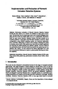
experimental results show that such is not always the case. Although variations on execution length were observed, no conclusion could be made regarding its relationship with the number of active SmartPacket threads. This was probably due to other management threads that were running in the background and consuming node resources. Asynchronous events in the virtual machine such as garbage collection also effect the execution time. Carefully designed experiments have to conducted in order to draw any sort of a conclusion in this case. We also ran some tests to find how much time it takes to allocate a thread for a SmartPacket. We observed that, on an average, the allocation of a new thread for a SmartPacket takes 1-3 milliseconds. The average waiting time for a SmartPacket from the moment the SmartPacket is handed to the Scheduler until the start of execution of the SmartPacket is about 10 msec under a normal load. We also performed some experiments to test the performance of the new services which were deployed. The performance measurements for mSMTP and mHTTP were carried out separately under different loads. Since mSMTP avoids multiple end to end delays by avoiding the ACKs. The performance is about 3-4 times better than the normal SMTP. The difference is substantial when the sending host and the receiving host are located close to each other. But when the hosts are geographically far apart from each other, the difference becomes noticeable. We then compared the performance of Netscape with mHTTP working as a filter proxy with Netscape running without a proxy. The performance of Netscape without a proxy was found to be better than with mHTTP functioning as a proxy as can be seen from Figure 13. This is because Netscape takes an aggressive approach while talking to the server. Typically, it opens up four connections simultaneously to the server. This approach works well when Netscape does not use a proxy because it acts as a client. However, this approach proves detrimental to mHTTP because it
4
3
2
1
0
0
1
2
3
4
5 6 Size of file in bytes
7
8
9
10 5
x 10
Figure 13. Comparison of Netscape Performance with and without mHTTP proxy.
But since the mHTTP cache stores data in the memory of an Active Node, its performance was found to be very much faster than normal disk based caches.
6. Related Work We are aware of similar recent work being carried out at MIT [13] where they send Tcl code inside IPv4 packets. A special option in the IP header identifies the IP packet as an Active Packet. When an Active node sees the option, it extracts the Tcl code from the body of the packet, spawns a Tcl interpreter and runs the Tcl program in it. They are also believed to be working on an implementation in Java. There are also some other efforts investigating Active Networks. The SwitchWare project [6] aims at developing a software switch to which programs may be downloaded to modify link behavior. Similarly, the Liquid Software project [7] is attempting to develop technologies which will allow use of mobile code inside the network. Researchers at Georgia Tech College of Computing [14] are trying to embed functions at network nodes. Each data packet carries control information including an identifier which selects one of the given functions, and a set of arguments that select the state information to be used in the computation. The user thus controls the 11
selection of the appropriate functions and the amount of state information that must be used.
7. Summary In this paper, we described our implementation of an Active Networking environment. This prototype enabled us to better understand the issues involved in creating, deploying, and using Active Networks. We described a format for SmartPackets and a model for an Active Node. We also looked at resource allocation issues and proposed some strategies. Toy protocols and services such as Geographical Routing, mSMTP and mHTTP were developed and deployed to demonstrate that network-level and application-level enhancements can be made easily by using the infrastructure provided by Active Networks. However, in this study, we did not delve deeply into the authentication and authorization issues surrounding Active Networks, nor did we study the impact of the language on the robustness and security of the implementation. We plan to extend our work by including these issues in our studies. Additionally, we plan to improve the performance of our prototype. In our current implementation, we used TCP to model the connections of our virtual network. We are now working towards extending our system to recognize SmartPackets encapsulated inside UDP datagrams. We would like to say in conclusion that Active Networking enables greater network flexibility and offers possibilities not available in current networks without a long standardization process.
References
Architecture for ATM WANs, Proceedings of the 3rd Mobile Multimedia Conference, September 1996. 4. J. Gosling and H. McGilton. The Java Language Environment: A White Paper, Sun Microsystems, 1995. 5. Y. Yemini and S. da Silva. Towards Programmable Networks, FIP/IEEE Intl. Workshop on Distributed Systems Operations and Management, 1996. 6. J. Smith, D. J. Farber, C. A. Hunter, S. M. Nettles, D. C. Feldmeier, and W. D. Sincoskie. SwitchWare: Accelerating Network Evolution, Technical Report MS-CIS-96-38, CIS Dept, Univ. of Pennsylvania, May 1996. 7. D. Mosberger and L. L. Peterson. Making Paths Explicit in the Scout Operating System, 2nd Symposium on Operating System Design and Implementation, 1996. 8. W. Stallings. Operating Systems, 2nd Edition, Prentice Hall, 1995. 9. Christopher Lefelhocz, Bryan Lyles, Scott Shenker and Lixia Zhang. Congestion Control for Best-Effort Service: Why We Need a New Paradigm, IEEE Network vol. 10(1), January 1996. 10. H.T. Kung and Koling Chang. ReceiverOriented Adaptive Buffer Allocation in CreditBased Flow Control For ATM Networks, Proc. Of the INFOCOM, pp. 239-252, 1995. 11. T. Imielinski, and J. Navas. GPS-based Addressing and Routing, RFC 2009, Computer Science Department, Rutgers University, New Jersey, 1996. 12. C. Farrell, M. Schulze, S. Pleitner, D. Baldoni, DNS Encoding of Geographical Location, Internet RFC 1712, Curtin University of Technology, 1994. 13. D. L. Tennenhouse and D. J. Wetherall. The ACTIVE IP Option. Proc. Of the 7th ACM SIGOPS European Workshop, Connemara, Ireland, September 1996. 14. S. Bhattacharjee, K. L. Calvert, and E. W. Zegura. On Active Networking and Congestion, Tech. Report GIT-CC-96/02, College of Computing, Georgia Tech., 1996.
1. D. L. Tennenhouse and D.J Wetherall. Towards an Active Network Architecture, Computer Communication Review, 1996. 2. D. L. Tennenhouse, J. M. Smith, W. D. Sincoskie, D. J. Wetherall, and G. J. Minden. A Survey of Active Network Research, IEEE Communications Magazine, Vol. 35, No. 1, pp. 80-86. January 1997. 3. Amit Kulkarni, Gary Minden, Victor Frost, and Joseph Evans. An Active Network 12