wireless mesh network architecture to solve the communication needs of the traffic .... The testbed is located in the Sydney CBD (Central Business. District) area.
Implementation of a Wireless Mesh Network Testbed for Traffic Control Kun-chan Lan∗ Zhe Wang∗,† Rodney Berriman∗ Tim Moors∗,§ Mahbub Hassan∗,† ∗ ∗ ∗,‡ ∗ ∗ Lavy Libman Maximilian Ott Bjorn Landfeldt Zainab Zaidi Aruna Seneviratne Doug Quail¶ ∗
National ICT Australia Bay 15, Australian Technology Park Eveleigh, NSW 1430, Australia §
†
School of Computer Science and Engineering University of New South Wales Sydney, NSW 2052, Australia
School of Electrical Engineering and Telecommunications University of New South Wales Sydney, NSW 2052, Australia
Abstract— Wireless mesh networks (WMN) have attracted considerable interest in recent years as a convenient, flexible and low-cost alternative to wired communication infrastructures in many contexts. However, the great majority of research on metropolitan-scale WMN has been centered around maximization of available bandwidth, suitable for non-real-time applications such as Internet access for the general public. On the other hand, the suitability of WMN for mission-critical infrastructure applications remains by and large unknown, as protocols typically employed in WMN are, for the most part, not designed for real-time communications. In this paper, we describe the Smart Transport and Roads Communications (STaRComm) project at National ICT Australia (NICTA), which sets a goal of designing a wireless mesh network architecture to solve the communication needs of the traffic control system in Sydney, Australia. This system, known as SCATS (Sydney Coordinated Adaptive Traffic System) and used in over 100 cities around the world, connects a hierarchy of several thousand devices — from individual traffic light controllers to regional computers and the central Traffic Management Centre (TMC) — and places stringent requirements on the reliability and latency of the data exchanges. We discuss our experience in the deployment of an initial testbed consisting of 7 mesh nodes placed at intersections with traffic lights, and share the results and insights learned from our measurements and initial trials in the process.
I. I NTRODUCTION Adaptive traffic control systems are employed in cities worldwide to improve the efficiency of traffic flows, reduce average travel times and benefit the environment via a reduction in fuel consumption. One of the main and most common functions of such systems lies in adaptive control of traffic lights. This ranges from simple lengthening or shortening of green and red light durations in an intersection according to the actual presence of cars in the respective lanes, to coordination of green light phases among neighboring intersections on main throughfares. This adaptivity is made possible with the use ∗ National ICT Australia is funded through the Australian Government’s Backing Australia’s Ability initiative, in part through the Australian Research Council.
‡
School of Information Technologies University of Sydney Sydney, NSW 2006, Australia
¶
Road and Traffic Authority of New South Wales Bay 3, Australian Technology Park Eveleigh, NSW 1430, Australia
of sensors (typically in the form of magnetic loop detectors embedded under the road pavement) that feed data to roadside traffic light controllers, and a communications infrastructure that connects among the intersections and a traffic management centre, as well as, in some cases (typically in large cities), a hierarchy of regional computers (RC) that perform the control decisions for respective portions of the system. Traditionally, the communications layer of traffic control systems has been based on wired connections, either private or leased from public telecommunications operators. While for many years such leased lines (operating at 300bps) have served their purpose well, they have several shortcomings, such as a significant operating cost, inflexibility, and difficulty of installation in new sites. In certain cases, alternative solutions, operating over public infrastructure, have been deployed for specific sites where private or leased lines were not a viable option; these ranged from ADSL, regular dialup, or cellular (GPRS). However, using public network for traffic control could suffer from inconsistent delay jitters and and reliability issues. For example, previous experimental studies [1] have shown GRPS links could have very high RTTs (>1000ms), fluctuating bandwidths and occasional link outages. In recent years, there has been considerable interest in wireless mesh networks and their deployment in metropolitan areas, from both a commercial and a research perspective. Trials in several major cities in the US (e.g. Philadelphia, New Orleans, and others [2], [3]) and worldwide (e.g. Taiwan [4]) have shown mesh networks to be a viable technology that can compete well with alternative “last-mile” connectivity solutions to the public. Correspondingly, most of the research on metropolitan-area wireless mesh networks (MAWMN) has focused on maximising the throughput that can be extracted from them, in the anticipation that their major use will be public, for purposes such as accessing the Internet or conducting voice calls [5]. On the other hand, little attention has been directed to the aspects of reliability and latency,
which are most important if MAWMN are to be considered for replacement of mission-critical infrastructure, such as traffic control system communications. The Smart Transport and Roads Communications (STaRComm) project at National ICT Australia (NICTA), started in August 2005, sets out to develop protocols that enhance the reliability and reduce the latency of mesh networks, and thereby enable them to be used as the communications layer of traffic control systems. In this paper, we describe the testbed that has been built in the first stage of this project. Our initial testbed covers seven traffic lights in the suburban area of Sydney. These intersections are chosen because they represent a typical suburban area with lots of traffic, foliages, pedestrians and high-rise residential buildings. In addition, the inter-node distance (ranging from 200 to-500m) is representative of 90% of the distance between traffic controllers in the Sydney CBD (Central Business District) area. In the next phase, we plan to extend our testbed to 15-20 nodes. Our nodes have been custom-built to meet the need of our research. The contribution of this paper are three-fold. First, to the best of our knowledge, our work is the first to study the feasibility of using wireless mesh networking for traffic control. Second, we describe the details of our testbed implementation and experience we gain during the deployment of the testbed in an urban environment. Finally, we present some initial measurement study of link characteristics of different wireless and wired technologies used in our testbed (including the use of 900MHz, 2.4GHz and 3.5GHz radios and Ethernet-overpowerline). The rest of this paper is structured as follows. We describe related work in Section II. Section III describes the details of our testbed implementation. We present some initial measurement results of link characteristics of different radio technologies used in our testbed in section IV. We conclude the paper and discuss the future work in section V. II. R ELATED WORK Roofnet [6] is an experimental 802.11b/g mesh network built by MIT. Each node in Roofnet has an antenna installed on the roof of a building. Aguayo et al. [7] analyzed the linklayer behavior on the Roofnet testbed and described the impact of distance, SNR and transmission rate on the packet loss. While Roofnet’s propagation environment is characterized by its strong Line-of-Sight component, our work differs from the prior work in that our links are generally heavily obstructed. In addition, our planned deployment strategy is different from the unplanned topology in Roofnet. Similar to our work, The WAND project [8] has built a multi-hop wireless testbed in the the centre of Dublin. They have 11 nodes mounted on traffic lights along a 2km route in urban area. However, their topology is simpler than ours (i.e. a chain topology) and the measurements they performed on their testbed were relatively limited. TFA project [9] aimed to provide broadband access to low income community in Houston area via wireless mesh network technology. Their architecture consist of two wireless tiers: an
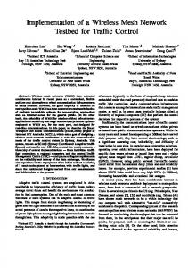
access tier to connect homes, businesses, and mobile users to the infrastructure, and a back-haul tier to forward traffic to and from the wired entry point. Jardosh et al. [10] discussed the correlation of link reliability with the frame retransmissions, frame sizes and data rate by collecting trace data from a structured 802.11b network during a international conference. They concluded that sending smaller frames and using higher data rates with a fewer number of frames improves the performance of congested network. All the previous studies have been centered around maximization of available bandwidth for non-real-time applications such as broadband access for the general public. On the other hand, to the best of our knowledge, our work is the first to focus on using wireless mesh networking for traffic control. which places stringent requirements on the reliability and latency of the data exchanges. III. T ESTBED In this section, we provide the details of our testbed. We first describe the environment that the testbed is located. Next, the hardware used for the initial seven nodes and the software installed on each of these nodes are discussed. A. Environment The testbed is located in the Sydney CBD (Central Business District) area. We selected seven intersections initially to deploy the testbed, as shown in Figure 1 (specifically, intersection number 521, 522, 523, 524, 413, 414 and 415). We plan to extend our testbed to 15-20 nodes in the next phase. We use a number of custom-build embedded PCs with multiple wireless interfaces. The nodes are mounted on the traffic lights at a height of about 2-3m from the ground, and distributed along the streets in the form of rectangle covering an area of 500 × 1000 square metres at a distance of 200-500m apart. None of the nodes is in a clear line of sights of its neighboring nodes. The node at intersection 521 is connected to a gateway node in University of Sydney.
Fig. 1. Map of Intersection locations (yellow dots are selected intersections)
•
•
•
Fig. 2.
Hardware Component)
•
Fig. 3.
Testbed topology
The streets where the network is deployed on are about 10-20m wide and surrounded by building at least two stories high. The majority of these buildings are made of concrete and steel that block the propagation of radio signals onto the neighboring streets. All these streets have busy public traffic during business hours. Most of the vehicles on the street have a height of less than 2.5m. But some double-decker buses (such as Sydney Explorer Bus) or truck can have a height of more than 5m. B. Hardware The hardware components used for the nodes of our initial testbed are all off-the-shelf products including the following, as shown in Figure 2. All the components are mounted on two sides of a metal plate for easy maintenance (for example, we can simply swap an old plate with a new plate when we want to upgrade the node). A custom-built enclosure is made to house this component plate.
•
Motherboard. A VIA MB720F Mini-ITX motherboard featuring an 1GHz processor and 1G memory is employed as the core in our system. Storage. The traffic pole sometimes vibrates a lot due to the passing traffic. Since that our node is mounted on a traffic pole, instead of using a hard-drive, we employ a 2G USB flash drive for storing OS and data. Unlike a hard-drive, a flash drive does not have a high-speed spinning platter and is less failure-prone. Wireless interfaces. Each node has two wireless interfaces to connect to its neighboring nodes, as shown in Figure 3. To allow the testbed users to experiment with different radio technologies, two different radio frequencies are currently used on our testbed: 2.4GHz (802.11b/g) and 900MHz radios. Specifically, the nodes at intersection 522, 523 and 414 ( i.e. m2, m3 and m6) are installed with two 2.4GHz mini-PCI wireless cards from Ubiquiti (SR2). The nodes at intersections 521 and 413 (i.e. m1 and m5) are equipped with one 2.4GHz Ubiquiti SR2 card (with a transmission power of 400mW) and one 900MHz Ubiquiti SR9 card (with a transmission power of 700mW). Finally, the nodes at intersections 524 and 415 (i.e. m4 and m7) are installed with two Ubiquiti SR2 cards. One of these two SR2 cards is connected to a 2.4GHz-to-900MHz converter (from RFlinx) to send 2.4GHz signal output by the wireless card on 900MHz band. Due to its better penetration rate for buildings and trees, theoretically the use of 900MHz radios could result in a better connectivity than 2.4GHz radios (i.e. 802.11x). Hence, we decided to install 900MHz radios on the nodes for intersection pairs 512-413 and 524-415. These two intersection pairs have a longer distance (i.e. 400m and 500m respectively) than the other intersection pairs. Back-haul connection. In addition to the two Ubiquiti wireless cards, each node is equipped an ”Unwired” modem [11] to establish a back-haul link back to NICTA for the purpose of remote management, as shown in Figure 3. Unwired is a Sydney-based metropolitan wireless ISP. The Unwired modem uses a proprietary protocol but claims to be a variant of WiMAX and operates in a licensed 3.5GHz band. Ethernet router. A Linux-based Ethernet router (Diamond Digital R100) is installed in each node. We employ this Ethernet router for several purposes. First, it is used as an Ethernet switch to connect the motherboard and the Unwired modem (and any IP-based devices such as a camera in the future). The Unwired modem is connected to the WAN port of the router, thus the router get a public Internet IP address. The motherboard has an Ethernet connection with the router’s 4-port switch. Second, the Diamond Digital router has an USB port which allow the motherboard to have a serial connection with the router’s USB port through an USB-to-serial adapter. Being able to establish a serial link to the motherboard allows the user to remotely login into the serial console for troubleshooting when the Ubiquity wireless interfaces are
not responding. Third, given that the router is a Linux box itself (runs on openWRT), we can run all the existing software (e.g. we are currently running DNS, NTP and VPN clients on it). Finally, the Diamond Digital router has an 802.11 wireless interface which can be used as an alternative link to remotely connect the mesh node in addition to Unwired and Ubiquity links. • Power. As shown in Figure 2, we use an off-the-shelf power-board (with surge protector and fuse) and a PC power-supply to provide the power to all the components in the node. The power-board takes a 240AC power from the traffic light. • Antenna. Nodes on our testbed are all installed with omni-directional antennas due to the following – Cost. An omni-directional antenna is typically cheaper than a directional antenna. In addition, for a node which has n neighbors, n directional antennas are needed. On the other hand, one omni-directional antenna per intersection is sufficient to cover all the neighbors. – Mounting. The space on the traffic light for the mounting of antennas is quite limited. It is comparatively more difficult to mount a directional antenna on the traffic pole in practice. We use an 8dBi omni-directional antenna for the 2.4GHz wireless card and an 6dBi omni-directional antenna for the 900MHz wireless card. • Weatherproof. The temperature in the summer can be above 40 Celsius degree in Sydney. The temperature inside the node can be even higher. As shown in Figure 2, to provide enough air circulation inside the node, we drilled many holes on the bottom of the enclosure and made some air louvres on the side. Two temperaturecontrolled fans are used in the node to dissipate the hot air out through the louvres. In addition, we mount a roof on top of the enclosure to shield the enclosure from direct sunlight and rain. • Remote recovery. Due to the fact that the testbed is deployed in an outdoor environment, it is time consuming to visit the nodes when something goes wrong. In addition, given that our nodes are mounted on the traffic lights which is a public asset, visiting any node on the testbed required calling out the RTA † maintenance crew to gain access to the node. Therefore, some means of remote recovery are necessary. Currently, we have one wireless remote switch installed on each node (runs in the unlicensed 433MHz band), which allows us to reboot the node on-site when accessing the node via the 2.4GHz or 3.5GHz links fails. The ultimate goal of our project is to control traffic lights using wireless mesh networks. However, due to practical consideration, we do not connect the mesh node directly to the real traffic controller in the first phase of the project. A † RTA is Roads and Traffic Authority of the state of New South Wales, formerly called Department of Main Roads
“dummy” traffic controller board is used instead. The main difference between the real traffic controller and the dummy traffic controller is that the data coming from the dummy traffic controller is fake data (and not the real sensor data coming from the road-side sensor). A pair of power-over-Ethernet adapters (Netcomm NP285) are used to connect the node to a dummy traffic traffic controller board in the curbside housing through the powerline. The dummy traffic controller board sends and receives data via a serial interface. Hence, a serialto-IP conversion is required for the communication between the dummy traffic controller and the testbed (which runs IP). We mount the traffic controller board inside an embedded PC and connect the traffic controller board to the embedded PC’s motherboard’s (VIA MB770F) serial port. A serial-to-IP converter software is written and run on the PC to encasuplate the SCATS data from the serial port of the traffic controller board into an IP packet as well as to descapsulate the IP packet from the regional computer and send its payload to the serial interface. In order to connect the testbed to the regional computer which is located at our facility, we deploy a gateway node at University of Sydney. The gateway node has a reasonable lineof-sight to intersection 521 and connects to the 521 node (i.e. m1) with a 802.11 link. Note that we do not use the Unwired links to connect the regional computer (RC) to the testbed due to the consideration of reliability, latency and cost issues. More details about the characteristics of Unwired links are described in Section IV. The RC is connected to the gateway node via AARNet [12]. Given that both NICTA and University of Sydney are members of AARNet, there is no cost to send traffic over AARNet. The round-trip delay between RC and the gateway is about 1.2ms, and the throughput is typically over 100Mbps. C. Software We use a custom-built Linux OS image that consists of the following components: • The image size is small enough to be fit into an USB flash drive. and run completely in RAM (1GB). This allows us to enable ’clean’ reboots uncontaminated by previous experiments • We add some kernel modifications for various driver support for USB, madwifi and PXE reboot. • We modify Grub to activate the watchdog timer at the time of boot-loading so that the watchdog timer can be started before any program start. Watchdog timer is used to reboot the motherboard when the system fails. • We include various tools including timesync, OpenVPN, some network support tools and software from Orbit project [13] in our image. The image is built to be Debian-based for the compatibility with Orbit software. We build our OS image based on DSL-N [14]. DSL-N provides most of the software support we need out of the box. The default syslinux bootloader of DSL-N is replaced with grub. We use OML software [15] from Orbit project to build the measurement collection infrastructure for the testbed. Two
IV. L INK
1000 ping latency
800
round-trip delay (ms)
security mechanism is currently implemented on our testbed. First, OpenVPN is used for the Unwired links from NICTA to each of the mesh nodes. Second, ssh and friends are used on all network interfaces. We plan to implement host-based and certificate-based access in the next phase. In addition, root access is disabled on all the machines.
600
400
CHARACTERSITCS 200
In this section, we describe some preliminary results of measured link latency from the testbed. We use ping to measure the round-trip delay. First, we look at the effect of hop number and distance on the link latency. We next compare the results when using different radio technologies for the same intersection pair. We then discuss the expected delay when running management traffic over the Unwired network. Finally, we show the link latency of Ethernet-over-powerline communication. Static routing was used in all our experiments.
0 0
1
2
3
4
5
number of hops
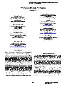
Fig. 5.
Effect of hop number on round-trip delay
3000 ping latency
2500
2000 ping latency
round-trip delay (ms)
1500
1000
500
0 100
200
300
400
intersection distance
Fig. 4.
Effect of distance on round-trip delay
500
2000 round-trip delay (ms)
As shown in Figure 5, the round-trip delay increases as the number of hops increases on the 802.11 links. In addition, the variation also increases significantly when there are more hops. We do not observe such a strong correlation between distance and link latency though. As shown in Figure 4, the latency does not increase from 300m to 400m. However, the variation increase significantly as the distance increases. One possibility is that there are more retries at 300m than at 400m due to different line-of-sight conditions. We are currently investigating this issue. Surprisingly, we observe that the use of 900MHz radio could sometimes introduce a larger latency and a larger variation, as shown in Figure 6. Our hypothesis is that the signal strength level when using 900MHz radio is higher than when 2.4GHz radio is used for the same environment. As a result, a larger number of MAC-layer retransmission occur when 900MHz radio is used. The larger number of MAC-layer retransmissions contribute the higher latency and variations. In other words, there are more packet losses but less MAC-layer retransmissions when 2.4GHz radio is used. However, packets lost in the air were not considered in our latency calculation.
1500
1000
500
0 0
900
2400 radio frequency (MHz)
Fig. 6.
Round-trip delays when using different radio technologies
We next examine the efficiency of powerline communication. As suggested in Figure 7, given a distance of 100m, the link latency of powerline communication is excellent. The average round-delay is about 3.6ms and the variations are very small. In addition, the largest delay for such a distance is less than 8ms. As described in Section III, we use the Unwired network to carry out our back-haul traffic. To understand the expected latency of running management traffic over the Unwired network, we measured the round-trip delay from a machine at NICTA to the mesh node. As shown in Figure 8(a), the average delay of sending traffic over the Unwired network to the mesh node is about 400ms. However, there are a large variation (the delay can be as long as 3 seconds) and significant number of outages. A closer look shows that the delay and outages over the Unwired network are mostly contributed by the wireless link between the mesh node and the Unwired base station. As shown in Figure 8(b), the average delay of the Unwired wireless link is about 200ms. The large delay variations and significant number of outages suggest that a public-shared wireless network like Unwired is not suitable for operating SCATS traffic.
1
3000 end-to-end latency from norbit to mesh node through Unwired
from mesh node to Unwired gateway from mesh node to NICTA
2500 0.8
0.6 Probability
round-trip delay (ms)
2000
1500
0.4 1000
0.2 500
0
0 0
500
1000
1500
2000
2500
3000
0
500
1000
time (sec)
(a) Round-trip delay from the mesh node to NICTA
Fig. 8.
latency
round-trip delay (ms)
8
6
4
2
0 500
Fig. 7.
1000 time (sec)
2000
2500
3000
(b) CDF comparison between the end-to-end delay (from mesh node to NICTA) and the Unwired wireless link delay (from mesh node to Unwired gateway)
Round-trip delay over the Unwired network
10
0
1500 round-trip delay (ms)
1500
2000
Latency of powerline communication
V. C ONCLUSION In this paper, we describe the details of our testbed implementation and some initial results of link characteristics of different technologies used on our testbed. While wireless mesh networks have been used in public safety and residential broadband for years, to the best of our knowledge, our work is one of the first attempts to use mesh network for traffic management. However, there are several research challenges such as latency, reliability, security and scalability that need to be addressed. We are currently developing innovative multipath routing and fast anomaly and fault detection schemes to address these issues. In addition, in the next phase, we plan to extend our testbed to 15-20 nodes as well as to cover a larger area. R EFERENCES [1] R. Chakravorty and I. Pratt, “Performance issues with general packet radio service,” Journal of Communications and Networks (JCN), Special Issue on Evolving from 3G deployment to 4G definition, vol. 4, no. 2, Dec. 2002. [Online]. Available: http://www.cl.cam.ac.uk/ Research/SRG/netos/papers/comob-web/2002-jcn.pd%f [2] http://www.tropos.com/, “Tropos networks,” http://www.tropos.com.
[3] http://www.locustworld.com/, “Locust world,” http://www.locustworld. com. [4] http://www.pwlan.org.tw/mp.asp?mp=3, “Mobile taiwan applications promotion project (m-taiwan),” http://www.pwlan.org.tw/mp.asp?mp=3. [5] S. Ganguly, V. Navda, K. Kim, A. Kashyap, D. Niculescu, R. Izmailov, S. Hong, and S. Das., “Performance optimizations for deploying voip services in mesh networks,” Performance Optimizations for Deploying VoIP Services in Mesh Networks, 2006. [Online]. Available: http://www.wings.cs.sunysb.edu/%7Eanand/papers/jsac06.pdf [6] J. Bicket, D. Aguayo, S. Biswas, , and R. Morris, “Architecture and evaluation of an unplanned 802.11b mesh network,” in Proceedings of the 11th annual international conference on Mobile computing and networking (MOBICOM), ologne, Germany, Sept. 2005. [Online]. Available: http://www.pdos.lcs.mit.edu/papers/roofnet: mobicom05/roofnet-mobicom05.%pdf [7] D. Aguayo, J. Bicket, S. Biswas, G. Judd, and R. Morris, “Link-level measurements from an 802.11b mesh network,” in Proceedings of the 10th annual international conference on Mobile computing and networking (MOBICOM), Philadelphia, PA, USA, Sept. 2004. [Online]. Available: http://research.microsoft.com/mesh/papers/multiradio.pdf [8] S. Weber, V. Cahill, S. Clarke, and M. Haahr, “Wireless ad hoc network for dublin: A large-scale ad hoc network testbed,” ERCIM News, vol. 54, 2003. [Online]. Available: http: //www.ercim.org/publication/Ercim˙News/enw54/weber.html [9] J. Camp, J. Robinson, C. Steger, and E. Knightly, “Measurement driven deployment of a two-tier urban mesh access network,” in Proceedings of ACM MobiSys 2006, Uppsala, Sweden, June 2006. [Online]. Available: http://networks.rice.edu/papers/sys7122-camp.pdf [10] A. Jardosh, K. Ramachandran, K. C. Almeroth, and E. M. Belding-Royer, “Understanding congestion in ieee 802.11b wireless networks,” in Proceeding of ACM SIGCOMM Internet Measurement Conference, Berkeley, CA, Oct. 2005. [Online]. Available: http: //moment.cs.ucsb.edu/˜amitj/jardosh-imc2005.pdf [11] http://www.unwired.com.au/, “Unwired wireless,” http://www.unwired. com.au/. [12] http://www.aarnet.edu.au/, “Aarnet - australia’s research and education network,” http://www.aarnet.edu.au/. [13] D. Raychaudhuri, I. Seskar, M. Ott, S. Ganu, K. Ramachandran, H. Kremo, R. Siracusa, H. Liu, and M. Singh, “Overview of the orbit radio grid testbed for evaluation of next-generation wireless network protocols,” in Proceedings of the IEEE Wireless Communications and Networking Conference, New Orleans, LA, USA, Mar. 2005. [14] http://www.damnsmalllinux.org/dsl n/, “Damn small linux not (dsl-n),” http://www.damnsmalllinux.org/dsl-n/. [15] M. Singh, M. Ott, I. Seskar, and P. Kamat, “Orbit measurements framework and library (oml): Motivations, design,implementation, and features,” in Proceedings of IEEE Tridentcom 2005, Trento, Italy, Feb. 2005.