adder. Parallel prefix adders are known to have the best performance. This project ... representation of binary signed-digit numbers not only allows carry-free ...
ISSN 2322-0929 Vol.02, Issue.11, December-2014, Pages:1186-1193
www.ijvdcs.org
Implementation of High Performance Spanning Tree Adder using Quaternary Logic GARNEPUDI SAI CHAND1, S. PRABHU DAS2 1
PG Scholar, Dept of ECE (VLSI & ES), Chirala Engineering College, Chirala, AP, India. 2 Assistant Professor, Dept of ECE, Chirala Engineering College, Chirala, AP, India.
Abstract: The adder is the critical element in most digital circuit designs including Digital Signal Processor and Micro Processor data path unit. As such, extensive research and usage continuous, it is focused on improving the performance of the adder. Parallel prefix adders are known to have the best performance. This project investigates parallel prefix adder i.e. spanning tree adders. In Existing VLSI implementation, the spanning tree adder is implemented using normal full adders. For implementing existing 16 bit addition design it requires 16 normal full adders. In the proposed design, Full adders can be replaced using Quaternary logic for improving the performance of the parallel prefix adder. At the same time, in this project, performance evaluation between the corresponding adders should be done based on the number of components (no of full adders). For implementing proposed16 bit addition including QSD design it requires only 8 normal full adders. In this project, Xilinx ISE tool is used for verifying the functionality and performing the synthesis also. The proposed design also extended to exist 16 bit to 64 bit also. Comparisons are done between the existed spanning and the proposed spanning with QSD based on the number of components (no of full adders) also. Keywords: Digital Signal Processor and Micro Processor Data Path Unit, QSD Design. I. INTRODUCTION These high performance adders are essential since the speed of the digital processor depends heavily on the speed of the adders used is the system. Also, it serves as a building block for synthesis of all other arithmetic operations. Adders are most commonly used in various electronic applications e.g. Digital signal processing in which adders are used to perform various algorithms like FIR, IIR etc. In past, the major challenge for VLSI designer is to reduce area of chip by using efficient optimization techniques. Then the next phase is to increase the speed of operation to achieve fast calculations like, in today’s microprocessors millions of instructions are performed per second. Speed of operation is one of the major constraints in designing DSP processors. The redundancy associated with signed-digit numbers offers the possibility of carry free addition. The redundancy provided in signed-digit representation allows for fast addition and subtraction because the sum or difference digit is a function of only the digits in two adjacent digit positions of the operands for a radix greater than 2, and 3 adjacent digit positions for a radix of 2. Thus, the add time for two redundant signed-digit numbers is a constant independent of the word length of the operands, which is the key to high speed computation. The advantage of carry free addition offered by QSD numbers is exploited in designing a fast adder circuit. Additionally adder designed with QSD number system has a regular layout which is suitable for VLSI implementation which is the great advantage over the RBSD adder. An
Algorithm for design of QSD adder is proposed. This algorithm is used to write the VHDL/Verilog code for QSD adders. VHDL/Verilog codes for QSD adder is simulated and synthesized and the timing report is generated. The timing report gives the delay time produced by the adder structure. Binary signed-digit numbers are known to allow limited carry propagation with a somewhat more complex addition process requiring very large circuit for implementation. A special higher radix-based (quaternary) representation of binary signed-digit numbers not only allows carry-free addition and borrow-free subtraction but also offers other important advantages such as simplicity in logic and higher storage density. II. ADDERS In electronics, an adder is a device which will perform the addition. In computing, the adder is part of the ALU, and some ALUs contain multiple adders. Although adders can be constructed for many numerical representations, such as BCD or excess-3, the most common adders operate on binary numbers. For single bit adders, there are two general types. A half adder has two inputs, generally labelled A and B, and two outputs, the sum S and carry output Co. S is the two-bit xor of A and B, and Co is the two-bit and of A and B. Essentially the output of a half adder is the two-bit arithmetic sum of two one-bit numbers, with Co being the most significant of these two outputs. The other type of single bit adder is the full adder which is like a half adder, but takes an additional input carry Ci. A full adder can be
Copyright @ 2014 IJVDCS. All rights reserved.
GARNEPUDI SAI CHAND, S. PRABHU DAS constructed from two half adders by connecting A and B to the input of one half adder, connecting the sum from that to an input to the second adder, connecting Ci to the other input and or the two carry outputs. Equivalently, S could be made the three-bit xor of A, B, and Ci and Co could be made the three-bit majority function of A, B, and Ci. The output of the full adder is the two-bit arithmetic sum of three one-bit numbers. The purpose of the carry input on the full-adder is to allow multiple full-adders to be chained together with the carry output of one adder connected to the carry input of the next most significant adder. The carry is said to ripple down the carry lines of this sort of adder, giving it the name ripple carry adder. Figure1. Half-Adder logic and block diagrams. There are also several types of multi-bit adders. The TABLE I: HALF-ADDER TRUTH TABLE ripple carry adder, described above, is the simplest type, as well as the slowest, since it requires changes to propagate through every full adder in the worst case. Carry lookahead adders work by creating Propagate and Generate signals (P and G) for each bit position, based on whether a carry is propagated through from a less significant bit position (at least one input is a '1'), a carry is generated in that bit position (both inputs are '1'), or if a carry is killed in that bit 2. Full Adder position (both inputs are '0'). In most cases, P is simply the A full adder is a combinational circuit that performs the sum output of a half-adder and G is the carry output of the arithmetic sum of three bits: A, B and a carry in, C, from a same adder. After P and G are generated the carries for previous addition, Fig. 2. Also, as in the case of the half every bit position are created. Some advanced carry adder, the full adder produces the corresponding sum, S, and lookahead architectures are the Manchester carry chain and a carry out Co. As mentioned previously a full adder maybe the Brent-Kung adder. Some other multi-bit adder designed by two half adders in series as shown below in architectures break the adder into blocks. It is possible to Figure 3. The sum of A and B are fed to a second half adder, vary the length of these blocks based on the propagation which then adds it to the carry in C (from a previous delay of the circuits to optimize computation time. These addition operation) to generate the final sum S. The carry block based adders include the carry bypass adder which out, Co, is the result of an OR operation taken from the will determine P and G values for each block rather than carry outs of both half adders. There are a variety of adders each bit, and the carry select adder which pre-generates sum in the literature both at the gate level and transistor level and carry values for either possible carry input to the block. each giving different performances A. Basic Adder Unit The most basic arithmetic operation is the addition of two binary digits, i.e. bits. A combinational circuit that adds two bits, according the scheme outlined below, is called a half adder. A full adder is one that adds three bits, the third produced from a previous addition operation. One way of implementing a full adder is to utilizes two half adders in its implementation. The full adder is the basic unit of addition employed in all the adders studied here 1. Half Adder A half adder is used to add two binary digits together, A and B. It produces S, the sum of A and B, and the corresponding carry out Co. Although by itself, a half adder is not extremely useful, it can be used as a building block for larger adding circuits (FA). One possible implementation is using two AND gates, two inverters, and an OR gate instead of a XOR gate as shown in Fig. 1. Boolean Equations: S = A B= A’B + AB’ Co = AB (1)
Figure2. Half-Adder logic and block diagrams.
International Journal of VLSI System Design and Communication Systems Volume.02, IssueNo.11, December-2014, Pages: 1186-1193
Implementation of High Performance Spanning Tree Adder using Quaternary Logic 4. Ripple-Carry adder The ripple carry adder is constructed by cascading full adders (FA) blocks in series. One full adder is responsible for the addition of two binary digits at any stage of the ripple carry. The carryout of one stage is fed directly to the carry-in of the next stage. A number of full adders may be added to the ripple carry adder or ripple carry adders of different sizes may be cascaded in order to accommodate binary vector strings of larger sizes. For an n-bit parallel adder, it requires n computational elements (FA). Figure 5 shows an example of a parallel adder: a 4-bit ripple-carry adder. It is composed of four full adders. The augend‟s bits of x are added to the addend bits of y respectfully of their binary position. Each bit addition creates a sum and a carry out. The carry out is then transmitted to the carry in of the Figure3. Full adder block diagram. next higher-order bit. The final result creates a sum of four bits plus a carry out (c4). Boolean Equations: S=C (A B) Co = AB + C( A B ) (2) TABLE II: FA TRUTH TABLE
3. Parallel adders Parallel adders are digital circuits that compute the addition of variable binary strings of equivalent or different size in parallel. The schematic diagram of a parallel adder is shown below in Fig. 4. Parallel adders let us add multipledigit numbers.
Figure4. Parallel Adder. In this project we will review the implementation technique of several types of adders and study their characteristics and performance. These are Ripple carry adder, or carry propagate adder, Carry look-ahead adder Carry skip adder, Carry-Select Adder
Figure5.Parallel Adder: 4-bit Ripple-Carry Adder Block Diagram. III. IMPLEMENTATION OF QUATERNARY HALF ADDER In quaternary logic, addition can be performed in many ways. Numbers in quaternary logic can be directly added or numbers in quaternary logic can be converted to binary logic and addition can be performed in binary logic. Binary results of addition can be displayed in quaternary logic after conversion. In quaternary logic, addition can be performed in many ways. Numbers in quaternary logic can be directly added or numbers in quaternary logic can be converted to binary logic and addition can be performed in binary logic. Binary results of addition can be displayed in quaternary logic after conversion. Hence quaternary to binary converter is required in the beginning. Binary to quaternary converter is used to display the result in quaternary logic. In [18] modulo-4 addition is introduced, without the hardware for implementation of carry. In this paper proposed half adder has hardware for carry also. Two bit natural representation of binary logic is used for each quaternary number and addition is performed in binary itself with only 4 gates. A. Sum Generator Block Sum generator circuit is shown figure 6. X0, X1 are the binary representation of the quaternary number X, and Y0 and Y1 are the two bit representation of quaternary number
International Journal of VLSI System Design and Communication Systems Volume.02, IssueNo.11, December-2014, Pages: 1186-1193
GARNEPUDI SAI CHAND, S. PRABHU DAS Y. S0 S1 are the outputs of sum generator block which is in binary. Minimal functions have been obtained from the Karnaugh diagrams for the tables shown in table 1 and then simplified as much as possible using all possible gate types. Minimal functions obtained from the minimal polynomials extracted from the Karnaugh diagrams are shown below.
(3)
Figure8. Carry generator circuit. TABLE III: TRUTH TABLE OF QUATERNARY HALF ADDER
Figure6. Block diagram of quaternary half adder circuit. B. CARRY Generator Block Carry generator circuit is shown figure 8. X0, X1 and Y0 Y1 are the input to the block. Co C1 are the outputs of the block. This circuit is designed by the expression obtained from the Karnaugh diagrams for the tables shown in table 1 and then simplified as much as possible using all possible gate types.
Figure7. Sum generator circuit. (4) The circuit contains two binary OR gates and three binary AND gates. Depth of the net is three. Simulation result shown in figure 14 to 17 verifies the table 1.
A basic Quaternary to binary converter uses three down literal circuits DLC1, DLC2, DLC3 and 2:1 multiplexer. Q is the quaternary input varying as 0, 1, 2 and 3 which is given to three DLC circuits. The binary out puts thus obtained will be in complemented form and are required to pass through inverters to get actual binary numbers. A basic binary to quaternary circuit consists of two PMOS and two NMOS transistors which form two inverters and two DLC 1 circuits. LSB and MSB of 2 bit binary numbers are given to two DLC1 circuits and output of two inverters will provide quaternary number.
International Journal of VLSI System Design and Communication Systems Volume.02, IssueNo.11, December-2014, Pages: 1186-1193
Implementation of High Performance Spanning Tree Adder using Quaternary Logic although directed graphs also play an important role in many applications. The following is a simple example of a connected, undirected graph with 5 vertices (A;B;C;D;E) and 6 edges (AB, BC, CD, AE, BE, CE) (fig 10).
Figure9. Proposed quaternary full adder. TABLE IV: TRUTH OF QUATERNARY FULL ADDITION, WHEN CARRY IN IS 1.
Proposed full adder circuit is based on Encoder, code generator, sum block and carry block. Encoder is required for the conversion shown in table 4, consists of DLC1 and DLC3 (Down literal circuit) [18]. Output codes of the Code generator are used to generate sum and carry of the full adder circuit. Block diagram of the full adder circuit is shown in figure 5. Logic levels of quaternary inputs 0, 1, 2 and 3 are represented by the voltage levels of 0V, 1V, 2V and 3V respectively. X and Y are the two quaternary inputs to the full adder. Table 2 shows sum and carry for all possible combinations of inputs when carry input is zero. Table 3 shows sum and carry for all possible combinations of inputs when carry input is one. C. Spanning Tree We start with undirected graphs which consist of a set V of vertices (also called nodes) and a set E of edges, each connecting two different vertices. A graph is connected if we can reach any vertex from any other vertex by following edges in either direction. In a directed graph edges provide a connection from one node to another, but not necessarily in the opposite direction. More mathematically, we say that the edge relation between vertices is symmetric for undirected graphs. In this lecture we only discuss undirected graphs,
Figure10. Examples of a connected, undirected graph with 5 vertices. In this chapter we are particularly interested in the problem of computing a spanning tree for a connected graph. What is a tree here? They are abit different than the binary search trees we considered early. One simple definition is that a tree is a connected graph with no cycles, where a cycle let’s you go from a node to itself without repeating an edge. A spanning tree for a connected graph G is a tree containing all the vertices of G. Below are two examples of spanning trees for our original example graph (fig 11).
Figure11. Examples of spanning trees for our original. When dealing with a new kind of data structure, it is a good strategy to try to think of as many different characterization as we can. This is somewhat similar to the problem of coming up with good representations of the data; different ones may be appropriate for different purposes. Here are some alternative characterizations the class came up with: 1. Connected graph with no cycle (original). 2. Connected graph where no two neighbors are otherwise connected. Neighbors are vertices connected directly by an edge, otherwise connected means connected without the connecting edge. 3. Two trees connected by a single edge. This is a recursive characterization. The based case is a single node, with the empty tree (no vertices) as a possible special case. 4. A connected graph with exactly n - 1 edges, where n is the number of vertices.
International Journal of VLSI System Design and Communication Systems Volume.02, IssueNo.11, December-2014, Pages: 1186-1193
GARNEPUDI SAI CHAND, S. PRABHU DAS 5. A graph with exactly one path between any two distinct AE, BE, CE). The first graph is the given graph, the vertices, where a path is a sequence of distinct vertices completely disconnected graph is the starting point for this where each is connected to the next by an edge. algorithm. At the bottom right we have computed the spanning tree, which we know because we have added n - 1 When considering the asymptotic complexity it is often = 4 edges. If we tried to continue, the next edge BE could useful to categorize graphs as dense or sparse. Dense graphs not be added because it does not connect two trees, and have a lot of edges compared to the number of vertices. neither can CE. The spanning tree is complete (fig 12). Writing n = |V| for the number of vertices (which will be our notation in the rest of the lecture) know there can be at most E. Carry-Tree Adder Designs n * (n-1)/2: every node is connected to any other node (n * Parallel-prefix adders, also known as carry-tree adders, (n-1)), but in an undirected way (n* (n-1)/2). If we write e pre-compute the propagate and generate signals. These for the number of edges, we have e = O(n2). By signals are variously combined using the fundamental carry comparison, a tree is sparse because e = n - 1 = O(n). operator (fco). D. Computing a Spanning Tree There are many algorithms to compute a spanning tree for a connected graph. The first is an example of a vertexcentric algorithm. 1. Pick an arbitrary node and mark it as being in the tree. 2. Repeat until all nodes are marked as in the tree: (a) Pick an arbitrary node u in the tree with an edge e to a node w not in the tree. Add e to the spanning tree and mark w as in the tree. We iterate n-1 times in Step 2, because there are n-1 vertices that have to be added to the tree. The efficiency of the algorithm is determined by how efficiently we can find a qualifying w. The second algorithm is edge-centric. 1. Start with the collection of singleton trees, each with exactly one node. 2. As long as we have more than one tree, connect two trees together with an edge in the graph.
Figure12. Complete spanning trees. This second algorithm also performs n steps, because it has to add n - 1edges to the trees until we have a spanning tree. Its efficiency is determined by how quickly we can tell if an edge would connect two trees or would connect two nodes already in the same tree, a question we come back to in the next lecture. Let’s try this algorithm on our first graph, considering edges in the listed order: (AB, BC, CD,
(gL, pL) ο (gR, pR) = (gL + pL•gR, pL • pR)
(1)
Due to associative property of the fco, these operators can be combined in different ways to form various adder structures. For, example the four-bit carry-look ahead generator is given by: c4 = (g4, p4) ο [ (g3, p3) ο [(g2, p2) ο (g1, p1)] ]
(2)
A simple rearrangement of the order of operations allows parallel operation, resulting in a more efficient tree structure for this four bit example: c4 = [(g4, p4) ο (g3, p3)] ο [(g2, p2 ) ο (g1, p1)]
(3)
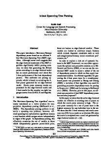
It is readily apparent that a key advantage of the tree structured adder is that the critical path due to the carry delay is on the order of log2N for an N-bit wide adder. The arrangement of the prefix network gives rise to various families of adders. For a discussion of the various carry-tree structures, see [1, 3]. For this study, the focus is on the spanning tree, known for having minimal logic depth and fanout. Here we designate BC as the black cell which generates the ordered pair in equation (1); the gray cell (GC) generates the left signal only, following The interconnect area is known to be high, but for an FPGA with large routing overhead to begin with, this is not as important as in a VLSI implementation. The regularity of the spanning tree prefix network has built in redundancy which has implications for fault-tolerant designs. This hybrid design completes the summation process with a 4 bit RCA allowing the carry prefix network to be simplified. This step involves computation of generate and propagate signals corresponding too each pair of bits in A and B. These signals are given by the logic equations below: pi = Ai XOR Bi gi = Ai AND Bi (5) This step involves computation of carries corresponding to each bit. It uses group propagate and generate as intermediate signals which are given by the logic equations below: Pi:j = Pi:k+1 AND Pk:j Gi:j = Gi:k+1 OR (Pi:k+1 AND Gk:j ) (6) Another important carry-tree adder known as the spanning tree carry-lookahead (CLA) adder is also
International Journal of VLSI System Design and Communication Systems Volume.02, IssueNo.11, December-2014, Pages: 1186-1193
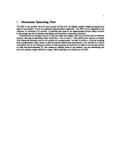
Implementation of High Performance Spanning Tree Adder using Quaternary Logic examined. This design terminates with a 4- bit RCA. As the B. Simulation Results FPGA uses a fast carry-chain for the RCA, it is interesting to compare the performance of this adder with the other adders. Also of interest for the spanning-tree CLA is its testability features.
Figure14. RTL Schematic 1.
Figure13. Spanning Tree Carry Lookahead Adder (16 bit). F. Spanning tree advantages Performance evaluation between the corresponding adders is done based on the number of components (no of full adders). In Existing VLSI implementation, the spanning tree adder is implemented using normal full adders. For implementing existing 16 bit addition design it requires 16 normal fulladders. For implementing proposed16 bit addition including QSD design it requires only 8 normal full adders. Thus, we can reduce the hardware using quaternary full adders.
Figure15. RTL Schematic 2.
G. Spanning tree applications In processors (DSP) and microprocessor data path units, adder is an important element. As such, extensive research continues to be focused on improving the power-delay performance of the adder. In VLSI implementations, parallel adders are known to have the best performance. H. Future scope of spanning tree In future there may be a chance to reduce further the number of required adders. At the same time it may be a chance to develop an ASIC chip for this project using BACK END TOOLS IV. RESULTS A. Synthesis Report Total delay = 21.071ns Total memory usage = 151044 kilobytes No of 4 input LUT’S = 127. Power = (75.92 x 127)/9312. = 1.03542mw.
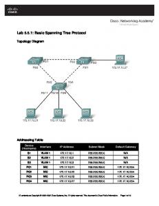
Figure16. Technology Schematic.
International Journal of VLSI System Design and Communication Systems Volume.02, IssueNo.11, December-2014, Pages: 1186-1193
GARNEPUDI SAI CHAND, S. PRABHU DAS Author’s Profile: Garnepudi. Sai Chand is pursuing M.Tech in VLSI &ES at Chirala Engineering College, Chirala, AP, India.
Figure17. Waveform. V. CONCLUSION Quaternary half adders are designed using binary logic gates and radix converters. This design is appropriate to be applied for construction of a high performance adder like spanning tree which consists of many full adder components and this can be reduced by using quaternary full adders in place of normal full adders.
Mr. S.PRABHU DAS at presently working as Associate Professor in Chirala Engineering College completed his B.Tech, ECE degree from JNTU Kakinada, Master Degree from JNTU College of Engineering with Computers and Communications Specialization and pursuing PhD from KL University. He has round 9 Years of Experience in Teaching Experience and presently working his research in the area of Digital Image Processing for Bio Medical Applications.
VI. REFERENCES [1] J. Savir and S. Patil, “Broad-side delay test,”IEEE Trans. Comput.-Aided Design Integr. Circuits Syst.,vol. 13, no. 8, pp. 1057–1064, Aug. 1994. [2] I. Pomeranz, “On the generation of scan-based test sets with reachable states for testing under functional operation conditions,” inProc. Design Autom. Conf., 2004, pp. 928– 933. [3] Y.-C. Lin, F. Lu, K. Yang, and K.-T. Cheng, “Constraint extraction for pseudo-functional scan-based delay testing,” inProc. Asia South Pacific DesignAutom.Conf., 2005, pp. 166–171. [4] Z.Zhang, S.M.Reddy, and I.Pomeranz,“On generating pseudo-functional delay fault tests for scan designs,” in Proc. Int. Symp. Defect Fault Toler. VLSI Syst., 2005, pp. 398–405. [5] I. Polian and F. Fujiwara, “Functional constraints vs. test compression in scan-based delay testing,” inProc. Design, Autom. Test Euro. Conf., 2006, pp. 1–6.
International Journal of VLSI System Design and Communication Systems Volume.02, IssueNo.11, December-2014, Pages: 1186-1193 The author has requested enhancement of the downloaded file. All in-text references underlined in blue are linked to publications on ResearchGate.