Implementation of Integrated Wireless Health Monitoring Network Bao Quach, Manikanden Balakrishnan, Driss Benhaddou, Xiaojing Yuan University of Houston, Texas, USA
[email protected] In-body medical network may require only moderate datarates and low radio ranges, which can be developed with personal area communication standards such as Zigbee/802.15.4. The data collection and distribution back-haul requires long-range and high-data rate technologies (WiFi) for wide area connectivity and managing data from several hundred sensors. A mobile communication interface is essential for anywhere anytime alarming about emergencies. These diverse wireless platforms cannot operate autonomously for efficient health tracking. This paper provides a practical implementation of the software and hardware solutions required to enable an integrated health monitoring platform.
Abstract Efficient wireless-networked health monitoring requires integrated operation of multiple platforms. In-body medical sensors can network using low-range personal area communication standards, such as Zigbee/802.15.4. The data collection and distribution back-haul requires long-range, high-data rate technologies (WiFi), and finally a mobile communication interface is essential for anywhere anytime alarming about emergencies. Enabling seamless information dissemination across these heterogeneous wireless platforms is crucial for efficient remote health monitoring. In this paper, we implement a laboratory prototype of wireless healthcare network using off-the-shelf wireless technologies. We detail the hardware components used and, in contrast with several existing works, we develop softwareinterfaces for integrated operation of a complete wireless tele-health system1.
Related work Networking distributed medical systems using advanced wireless technologies has attracted a lot of research effort in recent years. The remote patient monitoring system, developed by [1], demonstrated the ability to continuously transmit ECG signals to a remote server using Bluetooth [2] technology. A telemedicine system [3] extracted patient information in WAP [4] enabled phones operating with GSM communications. Codeblue [5], a multi-hop wireless sensor network for medical care being researched at Harvard, identifies the tremendous potential of embedded sensor nodes [6] to enhance healthcare applications. The lifeguard monitoring project at Stanford [7] uses Pocket PC as the base station to collect physiological signals from temperature, pulse, blood pressure, and ECG sensors. The work presented in [8] proposed a one-hop wireless sensor network architecture, where health monitoring sensors are directly connected to a PDA (sink), which provides the connectivity to a central medical server.
Categories & Subject Descriptors J.3. Medical Information Systems General Terms Design, Experimentation Keywords Wireless telehealth, sensor networks, embedded systems, wireless networking
I.
Introduction
Wireless telemedicine will be a breakthrough application for medical care. Developing wireless healthcare networks from existing established technologies will make the solutions affordable and easily deployable. Remote health monitoring networks will primary be heterogeneous due to the diverse application requirements.
Our work will complement the existing research efforts by addressing the crucial development gap of interfacing the autonomous wireless technologies including smart phones to enable integrated remote health monitoring. The paper is organized as follow; the following section presents the network architecture. Sections III, IV, and V describe different components of the integrated system architecture. Section 6 shows the demonstration of the system and conclusion.
1 This work was enabled by the financial support from ISSO (www.isso.uh.edu) post-doctoral and NSF-REU fellowships.
Permission to make digital or hard copies of all or part of this work for personal or classroom use is granted without fee provided that copies are not made or distributed for profit or commercial advantage and that copies bear this notice and the full citation on the first page. To copy otherwise, or republish, to post on servers or to redistribute to lists, requires prior specific permission and/or a fee. MobiHoc’09, May 18–21, 2009, New Orleans, Louisiana, USA. Copyright 2009 ACM 978-1-60558-531-4/09/05...$5.00.
63
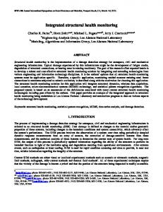
Figure 1. Integrated Health Monitoring Network: Laboratory Prototype
II.
Recent advancements in MEMS technology allow for penny-sized motes with efficient computing (upto 400MHz) and transmission capabilities (upto 100m), and thus a motebased wireless interface would not drastically increase the size of in-body medical components. Local processing capabilities will enable local biomedical signal analysis, synopsis (health inference) generation and transmission of only the vital signs, which will reduce the total medical traffic pushed out of the patient.
Network Architecture
The logical architecture of the implemented health monitoring network is shown in figure 1. It comprises three major components: 1) Data sensing and transmission module implements the user-end, where certain human physiological condition is sensed periodically, processed and is prepared for telecommunication. 2) Data collection/storage/distribution module represents the central medical server, which collects and stores all patient information for centralized processing and future retrieval. The server will be interfaced to a back-haul network for wide-area distribution (within and between hospitals).
Medical Signal Conditioning using PSoC The signal processing interface between the medical sensor and wireless transceiver is crucial for faithful regeneration of the waveforms at remote end. The voltage measure of physiological condition from medical sensors is typically very small (in the order of milliVolts) and has to be signal conditioned for wireless transmission. We are developing a medical-signal conditioning interface using Programmable System on Chip (PSoC) that will allow for rapid changes to component design through software programming (see figure 1).
3) Mobile component implements the alarming interface, which makes the healthcare providers independent of the need to be logged into server all the time for emergency tracking. The following sections explain each component in detail.
III.
The voltage reading from Pulse Plethysmogram transducer is fed into CYPRESS PSoC (CY8C29466-24PXI) for filtering and amplification, which is then fed as an analog input to the sensor mote. PSoC allows for rapid experimentations with filter design and other signal conditioning process (such as FFT), which is extremely time-efficient for identifying and separating the signal and noise components. The mote has a 12-bit ADC, which is programmed to sample the PSoC signal every 20ms (high sampling rate to avoid aliasing) and the digitized signal is ready for wireless transmission. Tmote uses the TinyOS operating system environment
Data Sensing and Transmission
In our prototype, we use Infrared Pulse Plethysmogram [9] to measure pulse pressure through blood density measurements from finger tips. The tmote sky sensor motes [6], operating using the 802.15.4/Zigbee [10] communications standard, serve as the local processing and wireless transceiver interface for the in-body medical sensor. The wireless transceiver can be wired to the medical-sensor and accepts analog or digital signal input (I/O ports) for wireless transmission.
64
and we developed a nesC driver that stores the PSoC data locally and constructs a data frame with up to 8 samples (pulse-readings) for transmission.
IV.
Central Data Collection
The health data from the Zigbee sensor network is collected centrally for storage, collaborative processing and future retrieval. The back-haul network represents the collection and distribution location of all patient information. In our network, the medical sensor information is distributed to the back-haul server network through a base-station sensor that is connected through USB port to a PC or PDA or both. eBox 2300 [11] is used as the PDA/smart-phone emulator, which provides Windows Mobile software development environment.
Figure 3. Serial Forwarder Logic
Figure 2: Data Extraction from Sensor Mote to PC/mobile-devices In-body sensors communicate to the base-station sensor and a serial forwarder application reads the 802.15.4 frames and extracts the medical information to the PC/PDA, after which we can use any existing medical database applications [12] for information storage and retrieval. Figure 2 shows the data extraction design. The serial forwarder firmware for PC is already implemented and the embedded version for mobile devices is currently under development. In this implementation, we use a simple SQL database to store the sensor information for concept validation.
If a mobile-device is also used as data collection entities, they merely serve as relay points between the medical sensors and central PC servers. As per figure 2, the handheld devices can act as collection point and use a WiFi connection to transfer the patient data to central severs with large databases. The serial forwarder application is written entirely in C# and depends only on the .NET framework,
65
which allows implementation in most wireless devices (PC/PDA/smart-phones).
the mobile-device through WiFi connection. We implemented mobile alarming through a push server architecture, where the medical processing servers push SMS messages when detecting abnormal health data. Push server also guarantees that the clients will receive the most updated data as soon as possible
Figure 3 shows the design of the serial forwarder softwareinterface that extracts data from USB connected sensor to a PC or PDA. The logic shows a relatively lighter database (XML) that can be used if there are memory and processing limitations (handheld devices).
Figure 5 shows the architecture of the push server program that is executed in the central medical servers. The software reads the data that is being logged into the database, identifies anomalies using threshold value comparison and pushes the data to clients (doctor devices) using a direct Wi-Fi connection. The server program can also push SMS alerts to remote clients that are not inside the Wi-Fi range. WiFi was the first choice notification interface due to the high communication speed. The above block diagram represents a general architecture. It uses Java as the main programming language, which has ready-to-use classes to access SMS messages. The software implementation comprises the following modules:
The choice of database can be flexible, since we could map one to the other if the data structure is designed uniformly. Figure 4 shows the mapping of SQL and XML database, which allows for data exchange and storage between the central PC servers and mobile devices (eBox).
V.
Mobile Alarming
The data transmission and collection components ensure that the sensor data is reliably stored at the remote (doctor) end for health tracking. However, the doctors still have to log into the servers to monitor patient information and detect any health anomalies. This dependency is a crucial limitation for handling emergency situations. In other words, any emergency health condition can only be noticed if the healthcare providers are connected to the data server network (cannot notice when sleeping or travelling).
Serial Forwarder Class: This is a modified version of serial listener provided by TinyOS. This version converts the raw data into decimal values, which are used to check for threshold values before sending the data to the database. SMS Class: This class contains the code to send a SMS message to the remote client using email. In order for this class to work, it is necessary to include the JavaMail and its prerequisites in the CLASSPATH of the host system because this class uses JavaMail API to access email. JavaMail can be downloaded from Sun Microsystem’s website along with the instruction to set it up in different operating systems such as Linux or Windows. We use the email-to-cell phone service provided by every cell phone carrier in the U.S. Each carrier provides an email address for each cell phone number in the format XXXXXX-XXXX@carrier where XXX-XXX-XXXX is the 10 digits U.S. phone number and carrier is the domain name of the specific carrier. Socket Server Class:
Figure 5. Push Server Architecture
This class contains a simple modification of an echo server to push data into a remote client when it is inside the Wi-Fi range. Once this class is invoked, it initializes a socket connection on port 9999 and then waits
The mobile alarming component in our prototype aims to overcome this limitation through automated alarm generation from the central servers to doctor mobile devices through SMS. Once notified about the pending emergency, the doctor can extract additional information from the medical server into
66
Figure 6. Demonstration of Data Collection and Mobile Alarming
VII.
for the client to connect in an infinite loop. Once there is a client connected to the server, it will start checking for new data using a flag, which will flip when new data is received by the serial forwarder class. After the socket server processes the data, it will reverse the flag for the next coming data.
VI.
Referenes
[1] Andreasson. J et al., “Remote system for patient monitoring using bluetooth” , Proceedings of IEEE , Volume: 1 , 2002 Page(s): 304 -307 [2] http://www.bluetooth.com [3] Hung, K.; Yuan-Ting Zhang, “Implementation of a WAP-based telemedicine system for patient monitoring”, IEEE Transactions on Information Technology in Biomedicine, Volume 7, Issue 2, June 2003 Page(s): 101 – 107 [4] http://www.wapforum.org/ [5] http://www.eecs.harvard.edu/~mdw/proj/codeblue/ [6] Crossbow Technology Inc. http://www.xbow.com [7] Lifeguard monitoring system. http://lifeguard.stanford.edu [8] Milenković, C. Otto, E. Jovanov, “Wireless Sensor Networks for Personal Health Monitoring: Issues and an Implementation, ”Computer Communications, Vol. 29, No. 13 14, 2006, pp. 2521-2533 [9] Pulse Plethysmogram (SS4LA), http://www.biopac.com [10] http://www.zigbee.org [11] http://www.embeddedpc.net/ [12] http://www.apple.com/medicine
Demonstration and Conclusions
Figure 6 shows the demonstration of data collection and alarming in mobile phone/smart phone prototyped using the e-box. The SMS alarming system was demonstrated using a real smart phone with an actual operator. In this paper, we provided a implementation of an integrated healthcare network that combined the advantages of 802.15.4, 802.11 and mobile technologies for efficient remote health monitoring and alarming. The crucial gap that needs to be filled is the appropriate software interface development for wireless platform integration. In this work, we developed drivers that enabled seameless information flow across the 802.15.4, 802.11 and mobile platforms. Also, introducing mobile component is crucial for handling emergency situations. Mobile health monitoring will allow for patients to be monitored without being confined within hospital environments.
67