Dec 4, 2013 - 2 Time Division Multiple Access (TDMA) is a .... 2 Multiple carriers cause IM in both the SES HPA ...... the later Intelsat VI spacecraft, known as.
the International Journal
http://www.transnav.eu
on Marine Navigation and Safety of Sea Transportation
Volume 7 Number 4 December 2013 DOI: 10.12716/1001.07.04.08
Implementation of Multiple Access Techniques Applicable for Maritime Satellite Communications S.D. Ilcev Durban University of Technology (DUT), South Africa
ABSTRACT: In this paper are introduced fundamentals, characteristics, advantages and disadvantages of Multiple Access (MA) employed as transmission techniques in the Maritime Mobile Satellite Communications (MMSC) between ships and Coast Earth Station (CES) via Geostationary Earth Orbit (GEO) or Not‐GEO satellite constellations. In fixed satellite communication, as a rule, especially in MMSC many users are active at the same time. The problem of simultaneous communications between many single or multipoint mobile satellite users can be solved by using MA technique, such as Frequency Division Multiple Access (FDMA), Time Division Multiple Access (TDMA), Code Division Multiple Access (CDMA), Space Division Multiple Access (SDMA) and Random (Packet) Division Multiple Access (RDMA). Since the resources of the systems such as the transmitting power and the bandwidth are limited, it is advisable to use the channels with complete charge and to create a different MA to the channel. This generates a problem of summation and separation of signals in the transmission and reception parts, respectively. Deciding this problem consists in the development of orthogonal channels of transmission in order to divide signals from various users unambiguously on the reception part.
1 INTRODUCTION Fixed and mobile satellite communication systems are using five principal forms of MA techniques: 1 Frequency Division Multiple Access (FDMA) is a scheme where each concerned Earth Station, such as Coast Earth Station (CES) or Ship Earth Station (SES), is assigned its own different working carrier Radio Frequency (RF) inside the spacecraft transponder bandwidth. 2 Time Division Multiple Access (TDMA) is a scheme where all concerned Earth stations use the same carrier RF and bandwidth with time sharing and non‐overlapping intervals. 3 Code Division Multiple Access (CDMA) is a scheme where all concerned Earth stations simultaneously share the same bandwidth and
recognize the signals by various processes, such as code identification. Actually, they share the resources of both frequency and time using a set of mutually orthogonal codes, such as a Pseudorandom Noise (PN) sequence. 4 Space Division Multiple Access (SDMA) is a scheme where all concerned Earth stations can use the same RF at the same time within a separate space available for each link. 5 Random (Packet) Division Multiple Access (RDMA) is a scheme where a large number of satellite users share asynchronously the same transponder by randomly transmitting short burst or packet divisions. Currently, these methods of multiple access are widely in use with many advantages and 529
disadvantages, together with their combination of hybrid schemes or with other types of modulations. Hence, multiple access technique assignment strategy can be classified into three methods as follows: (1) Preassignment or fixed assignment; (2) Demand Assignment (DA) and (3) Random Access (RA); the bits that make up the code words in some predetermined fashion, such that the effect of an error burst is minimized. In the preassignment method channel plans are previously determined for chairing the system resources, regardless of traffic fluctuations. This scheme is suitable for communication links with a large amount of traffic between receivers (Rx and transmitters (Tx). Since most SES users in MMSC do not communicate continuously, the preassignment method is wasteful of the satellite resources. In Demand Assignment Multiple Access (DAMA) satellite channels are dynamically assigned to mobile users according to the traffic requirements. Due to high efficiency and system flexibility, DAMA schemes are suited to MSC systems.
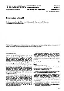
Figure 1. Multiple Access Techniques Courtesy of Book: “Global Communications” by Ilcev [01]
Mobile
Satellite
In RA a large number of mobile users use the satellite resources in bursts, with long inactive intervals. So, to increase the system throughout, several mobile Aloha methods have been proposed. Therefore, the MA techniques permit more than two Earth stations to use the same satellite network for interchanging information. In such a way, several transponders in the satellite payload share the RF bands in use and each transponder will act independently of the others to filter out its own allocated RF and further process that signal for transmission. Thus, this feature allows any maritime CES located in the corresponding coverage area to receive carriers originating from several SES and vice versa and carriers transmitted by one SES can be received by any CES. This enables a transmitting Earth station to group several signals into a single, multi‐destination carrier. Access to a transponder may be limited to single carrier or many carriers may exist simultaneously. The baseband information to be transmitted is impressed on the carrier by the single process of multi‐channel modulation [01, 02, 03, 04].
2 FREQUENCY DIVISION MULTIPLE ACCESS (FDMA) The most common and first employed MA scheme for satellite communication systems is FDMA concept shown in Figure 1. (FDMA), where transmitting signals occupy non‐overlapping RF bands with guard bands between signals to avoid interchannel interference. The bandwidth of a repeater channel is therefore divided into many sub‐bands each assigned 530
to the carrier transmitted by an SES continuously. In such a way, the channel transmits several carriers simultaneously at a series of different RF bands. Because of interchannel interference, it is necessary to provide guard intervals between each band occupied by a carrier to allow for the imperfections of oscillators and filters. The downlink Rx selects the required carrier in accordance with the appropriate RF. When the satellite Tx is operating close to its saturation, nonlinear amplification produces intermodulation (IM) products, which may cause interference in the signals of other users. In order to reduce IM, it is necessary to operate the transponder by reducing the total input power according to input back off and that the IF amplifier provides adequate filtering. Therefore, FDMA allocates a single satellite channel to one mobile user at once. In fact, if the transmission path deteriorates, the controller switches the system to another channel. Although technically simple to implement, FDMA is wasteful of bandwidth because the voice channel is assigned to a single conversation, whether or not somebody is speaking. Moreover, it cannot handle alternate forms of data, only voice transmissions. This system’s advantages are that it is simple technique using equipment proven over decades to be reliable and it will remain very commonly in use because of its simplicity and flexibility. It does have some disadvantages however: 1 An FDMA method is the relatively inflexible system and if there are changes in the required capacity, then the RF plan has to change and thus, involve many CES. 2 Multiple carriers cause IM in both the SES HPA and in the transponder HPA. Reducing IM requires back off of the HPA power, so it cannot be exploited at full capacity. 3 As the number of carriers increase, the IM products between carriers also increase and more HPA back off is needed to optimize the system. The throughput decreases relatively rapidly with the number of transmission carriers, therefore for 25 carriers it is about 40% less than with 1 carrier. 4 The FM system can suffer from what is known as a capture effect, where if two received signals are very close in RF but of different strengths, the stronger one tends to suppress the weaker one. For this reason the carrier power has to be controlled carefully. Thus, with the FDMA technique, the signals from the various users are amplified by the satellite transponder in a given allocated bandwidth at the same time but at different frequencies. Depending on the multiplexing and modulation techniques employed, several transmission hybrid schemes can be considered and in general may be divided into two categories, based on the traffic demands of Earth stations on MCPC and SCPC. 1 Multiple Channels Per Carrier (MCPC) – Its main elements are multiplexer, modulator and transmitter using a satellite uplink, when CES multiplexes baseband data is received from a terrestrial network and destined for various SES terminals. Then the multiplexed data are modulated and transmitted to the allocated RF
segment, when the bandwidth of the transponder is shared among several SES units, each with different traffic requirements. The transponder bandwidth is divided into several fixed segments, with several time frequency divisions allocated to these SES units and between each band segment is a guard band, which reduces the bandwidth utilization efficiency and the loss is directly related to the number of accessing SES in the network, see Figure 1 (FDMA). Depending on the number of receiving SES units, a total number of carriers will pass through the satellite transponder. The signals received from different SES units extract the carrier containing traffic addressed to CES by using an appropriate RF filter, demodulator, baseband filter and demultiplexer. The output of the demodulator consists in multiplexed telephone channels, a baseband filter is used to filter out the desired baseband frequency and a demultiplexer retrieves individual telephone channels and feeds them into the terrestrial network for onward transmission. Each baseband filter of LES receive stations in this scheme corresponds to a specific one in the LES transmitting station. 2 Single Channel Per Carrier (SCPC) – For certain applications, such as the provision of MMSC service to remote areas or individual SES, traffic requirements are low. In reality, assigning multiple channels to each SES is wasteful of bandwidth because most channels remain unutilized for a significant part of the day. For this type of application the SCPC type of FDMA is used. In the SCPC system each carrier is modulated by only one voice or by low to medium bit rate data channel. Some old analog systems use Companded FM but most new systems are digital PSK modulated. In the SCPC scheme, each carrier transmits a single carrier. The assignment of transponder channels to each SES may be fixed Pre‐Assigned Multiple Access (PAMA), about 5 to 10 channels, or variable Demand‐Assigned Multiple Access (DAMA), when a pool of frequency is shared by many SES terminals. When necessary, each SES requests a channel from RF management of the Network Control Station (NCS), which may always attempt to choose the best available channel or a lower quality channel until an unoccupied channel has been found. The SCPS solution requires an Automatic Frequency Control (AFC) pilot to maintain the spectrum centering on a channel‐by‐channel basis. This is usually achieved by transmitting a pilot tone in the centre of the transponder bandwidth. It is transmitted by designated reference CES and all the SES units use this reference to correct their transmission frequency. A receiving station uses the pilot tone to produce a local AFC system, which is able to control the frequency of the individual carriers by controlling the frequency of the Local Oscillator (LO). This scheme is cost‐ effective for networks consisting in a significant number of Earth stations, each needing to be equipped with a small number of channels. Using this scheme, Inmarsat system of A, B, C, M, Fleet 33/55/77 and FleetBroadband standards can simply provide a higher usage of channels and can utilize demand‐assignment equipment.
There are few hybrids of multiplexed FDMA combined with SCPS, PSK, TDM and TDMA techniques: 1 SCPC/FM/FDMA – The baseband signals from the network or users each modulate a carrier directly, in either analog or digital form according to the nature of SCPC signal in question. Each carrier accesses the satellite on its particular frequency at the same time as other carriers on the different frequencies from the same or other station terminals. Information routing is thus, performed according to the principle of one carrier per link utilizing analog transmission with FM for SES telephone channels. For calculation of channel capacity of this scheme it is necessary to ensure that the noise level does not exceed specified defined values. 2 SCPC/PSK/FDMA – Each voice or data channel is modulated onto its own RF carrier using this scheme. The only multiplexing occurs in the transponder bandwidth, where frequency division produces individual channels within the bandwidth. Various types of this multiplex scheme are used in channels of the Inmarsat standard‐B SES. In this case, the satellite transponder carrier frequencies may be PAMA or DAMA. For PAMA carriers the RF is assigned to a channel unit and the PSK modem requires a fixed‐frequency LO input. For DAMA, the channels may be connected according to the availability of particular carrier frequencies within the transponder RF bandwidth. For this arrangement, the SCPC channel frequency requirement is produced by a frequency synthesizer. The forward link assigned by TDM in shore‐to‐ship direction uses the SCPC/DA/FDMA solution for Inmarsat standard‐B voice/data transmission. This standard in the return link for channel request employs Aloha O‐QPSK and for low speed data/telex uses the TDMA scheme in ship‐to‐shore direction. The Inmarsat‐Aero in forward ground‐to‐aircraft direction uses packet mode TDM for network broadcasting, signaling and data and the circuit mode of SCPS/DA/FDMA with distribution channel management for service communication links. Thus, the request for channel assignment, signaling and data in the return aircraft‐to‐ground direction the Slotted Aloha BPSK (1/2 – FES) of 600 b/s is employed and consequently, the TDMA scheme is reserved for data messages. 3 TDM/FDMA – This arrangement allows the use of TDM groups to be assembled at the satellite in FDMA, while the PSK is used as a modulation process at the Earth station. Systems such as this are compatible with FDM/FDMA carriers sharing the same transponders and the terminal requirements are simple and easily incorporated. The Inmarsat standard‐B system for telex low speed data uses this scheme in the shore‐to‐ship direction only and in the ship‐to‐shore direction uses TDMA/FDMA. The CES TDM and SES TDMA carrier frequencies are pre‐allocated by Inmarsat. Each CES is allocated at least one forward CES TDM carrier frequency and a return SES TDMA frequency. So, additional allocations can be made depending on the traffic requirements. The channel unit associated with the CES TDM channel for transmission consists in a 531
multiplexer, different encoder, frame transmission synchronizer and modulator. So at the SES, the receive path of the channel has the corresponding functions to the transmitted end. The CES TDM channels use BPSK with differential coding, which is used for phase ambiguity resolution at the receive end. 4 TDMA/FDMA – As is known, the TDMA signals could occupy the complete transponder bandwidth. In fact, a better variation of this is where the TDMA signals are transmitted as a sub‐ band of transponder bandwidth, the remainder of which being available for example for SCPC/FDMA signals. Thus, the use of a narrowband TDMA arrangement is well suited for a system requiring only a few channels and has the all advantages of satellite digital transmission but can suffer from intermodulation with the adjacent FDMA satellite channels. Accordingly, the practical example of this multiple schemes is the Tlx (Telex) service of the Inmarsat Standard‐B system in ship‐to‐shore direction, which, depending on the transmission traffic, offers a flexible allocation of capacity for satellite communication and signaling slots [01, 03, 05, 06].
3 TIME DIVISION MULTIPLE ACCESS (TDMA) The TDMA application is a digital MA technique that permits individual Earth station transmissions to be received by the satellite in separate, non‐overlapping time slots, called bursts, which contain buffered information. The satellite receives these bursts sequentially, without overlapping interference and is then able to retransmit them to the SES terminal. Synchronization is necessary and is achieved using a reference station from which burst position and timing information can be used as a reference by all other stations. Each SES must determine the satellite system time and range so that the transmitted signal bursts, typically QPSK modulated, are timed to arrive at the satellite in the proper time slots. The offset QPSK modulation is used by Inmarsat‐B SES. So as to ensure the timing of the bursts from multiple SES, TDMA systems use a frame structure arrangement to support Tlx in the ship‐to‐shore direction. Therefore, a reference burst is transmitted periodically by a reference station to indicate the start of each frame to control the transmission timing of all data bursts. A second reference burst may also follow the first in order to provide a means of redundancy. In the proper manner, to improve the imperfect timing of TDMA bursts, several synchronization methods of random access, open‐loop and closed‐loop have been proposed. In Figure 1 (TDMA) a concept of TDMA is illustrated, where each SES terminal transmits a data burst with a guard time to avoid overlaps. Since only one TDMA burst occupies the full RF bandwidth of the satellite transponder at a time, input back off, which is needed to reduce IM interference in FDMA, is not necessary in TDMA. At any instant in time, the transponder receives and amplifies only a single carrier. Thus, there can be no IM, which permits the satellite amplifier to be operated in full HPA saturation and the transmitter carrier power need not 532
be controlled. Because all SES units transmit and receive at the same frequency, tuning is simplified. This results in a significant increase in channel capacity. Another advantage over FDMA is its flexibility and time‐slot assignments are easier to adjust than RF channel assignments. The transmission rate of TDMA bursts is about 4,800 b/s, while the frame length is about 1.74 seconds and the optimal guard time is approximately 40 msec, using the open‐ loop burst synchronization method. There are some disadvantages because TDMA is more complex than FDMA: 1 Two reference stations are needed and complex computer procedures, for automated synchronizations between SES terminals. 2 Peak power and bandwidth of individual SES terminals need to be larger than with FDMA, owing to high burst bit rate. Accordingly, in the TDMA scheme, the transmission signals from various mobile users are amplified at different times but at the same nominal frequency, being spread by the modulation in a given bandwidth. Depending on the multiplexing techniques employed, two transmission hybrid schemes can be introduced for use in MMSC systems. 1 TDM/TDMA – The Inmarsat analog standard‐A uses the TDM/TDMA arrangement for telex transmission. Each SES has at least one TDM carrier and each of the carriers has 20 telex channels of 50 bauds and a signaling channel. Moreover, there is also a common TDM carrier continuously transmitted on the selected idle listening frequency by the NCS for out‐of‐band signaling. The SES remains tuned to the common TDM carrier to receive signaling messages when the ship is idle or engaged in a telephone call. When an SES is involved in a telex forward call it is tuned to the TDM/TDMA frequency pair associated with the corresponding CES to send messages in shore‐to‐ship direction. Telex transmissions in the return ship‐to‐shore direction form a TDMA assembly at the satellite transponder. Each frame of the return TDMA telex carrier has 22 time slots, while each of these slots is paired with a slot on the TDM carrier. The allocation of a pair of time slots to complete the link is received by the SES on receipt of a request for a telex call. Otherwise, the Inmarsat‐A uses for forward signaling a telex mode, while all other MSS Inmarsat standards for forward signaling and assignment channels use the TDM BPSK scheme. The new generation Inmarsat digital standard‐B (inheritor of standard‐A) uses the same modulation TDM/TDMA technique but instead of Aloha BPSK (BCH) at a data rate of 4800 b/s for the return request channel used by Inmarsat‐A, new standard‐B is using Aloha O‐QPSK (1/2 – FEC) at a data rate of 24 Kb/s. This MA technique is also useful for the Inmarsat standard‐C terminal for maritime, land and aeronautical applications. In this case, the forward signaling and sending of messages in ground‐to‐mobile direction use a fixed assigned TDM carrier. The return signaling channel uses hybrid, slotted Aloha BPSK (1/2 FEC) with a provision for receiving some capacity and the return message channels in the mobile‐to‐
ground direction are modulated by the TDMA system at a data rate of 600 b/s. 2 FDMA/TDMA – The Iridium mobile system employs a hybrid FDMA/TDMA access scheme, which is achieved by dividing the available 10.5 MHz bandwidth into 150 channels introduced into the FDMA components. Each channel accommodates a TDMA frame comprising eight time slots, four for transmission and four for reception. Each slot lasts about 11.25 msec, during which time data are transmitted in a 50 Kb/s burst. Each frame lasts 90 msec and a satellite is able to support 840 channels. Therefore, a user is allocated a channel occupied for a short period of time, during which transmissions occur [01, 03, 07, 08].
4 CODE DIVISION MULTIPLE ACCESS (CDMA) The modern CDMA solution is based on the use the modulation technique also known as Spread Spectrum Multiple Access (SSMA), which means that it spreads the information contained in a particular signal of interest over a much greater bandwidth than the original signal. In this MA scheme the resources of both frequency bandwidth and time are shared by all users employing orthogonal codes, shown in Figure 1 (CDMA). The CDMA is achieved by a PN (Pseudo‐ Noise) sequence generated by irreducible polynomials, which is the most popular CDMA method. In this way, a SSMA method using low‐rate error correcting codes, including orthogonal codes with Hadamard or waveform transformation has also been proposed. Concerning the specific encoding process, each user is actually assigned a signature sequence, with its own characteristic code, chosen from a set of codes assigned individually to the various users of the system. This code is mixed, as a supplementary modulation, with the useful information signal. On reception side, from all the signals that are received, a given mobile user is able to select and recognize, by its own code, the signal, which is intended for it, and then to extract useful information. The other received signal can be intended for other users but they can also originate from unwanted emission, which gives CDMA a certain anti‐jamming capability. For this operation, where it is necessary to identify one CDMA transmission signal among several others sharing the same band at the same time, correlation techniques are generally employed. From a commercial and military perspective this MA is still new and has significant advantages. Interference from adjacent satellite systems including jammers is better solved than with other systems. This scheme is simple to operate as it requires no synchronization of the Tx and is more suited for a military SES. Small antennas can be very useful in these applications, without the interference caused by wide antenna bandwidths. Using multibeam satellites, frequency reuse with CDMA is very effective and allows good flexibility in the management of traffic and the orbit/spectrum resources. The Power Flux Density (PFD) of the CDMA signal received in the service area is automatically limited, with no need for any other dispersal processes. It also provides a low probability
of intercept of the users and some kind of privacy, due to individual characteristic codes. The main disadvantage of CDMA by satellite is that the bandwidth required for the space segment of the spread carrier is very large, compared to that of a single unspread carrier, so the throughput is somewhat lower than with other systems. Using this scheme, the signals from various users operate simultaneously, at the same nominal RF, but are spread in the given allocated bandwidth by a special encoding process. Depending on the multiplexing techniques employed the bandwidth may extend to the entire capacity of the transponder but is often restricted to its own part, so CDMA can possibly be combined in the hybrid scheme with FDMA and/or TDMA. The SSMA technique can be classified into two methods: Direct Sequence (DS) and Frequency Hopping (FH). A combined system of DC and FH is called a hybrid CDMA system and the processing gain can be improved without increases of chip rate. The hybrid system has been used in the military Joint Tactical Information Distribution System (JTIDS) and OmniTRACS, which is Ku‐band mobile satellite system, developed by the Qualcomm Company. In a more precise sense, the CDMA technique was developed by experts of the Qualcomm Company in 1987. At present, the CDMA system advantages are practically effective in new satellite systems, such as Globalstar, also developed by Qualcomm, which is devoted to mobile satellite handheld terminals and Skybridge, involved in fixed satellite systems. This type of MA is therefore attractive for handheld and portable satellite equipment with a wide antenna pattern. Antennas with large beam widths can otherwise create or be subject to interference with adjacent satellites. In any case, this MA technique is very attractive for commercial, military and even TT&C communications because some Russian satellites use CDMA for command and telemetry purposes. The Synchronous-CDMA (S-CDMA) scheme proves efficiently to eliminate interference arising from other users sharing the same carrier and the same spot beam. Interference from other spot beams that overlap the coverage of the intended spot is still considerable. This process to ensure orthogonality between all links requires signaling to adjust transmission in time and frequency domains for every user independently. 1. Direct Sequence (DS) CDMA – This DS‐CDMA technique is also called Pseudo‐Noise (PN) modulation, where the modulated signal is multiplied by a PN code generator, which generates a pseudo‐ random binary sequence of length (N) at a chip rate (Rc), much larger than information bit rate (Rb). The chip rate sequence is introduced by the following relation: Rc = N ∙ Rb
(1)
This sequence is combined with the information signal cut into small chip rates (Rc), thus, speeding the combined signal in a much larger bandwidth (W~Rc). The resulting signal has wider RF bandwidth than the original modulated signal. In such a way, the 533
transmitting signal can be expressed in the following way:
The transmitted and received signals have the following forms:
s(t) = m(t) p(t) cos (2πfct) = m(t) p(t) cos ωct
s(t) = m(t) cos ωc(t) t and r(t) = m(t) cos ωc(t) t ∙ 2 cos ωc(t) t = m(t) + m(t) cos 2ωc(t) t (6)
(2)
where m(t) = binary message to be transmitted and p(t) = spreading NP binary sequence. Consequently, at the receiver the signal is coherently demodulated by multiplying the received signal by a replica of the carrier. Neglecting thermal noise, the receiving signal at the input of the detector of Low‐Pass Filter (LPF) is given by the following equation: r(t) = m(t) p(t) cos ωct (2 cos ωct) = m(t) p(t) + m(t) p(t) cos 2ωct (3) The detector LLF eliminates the HF components and retains only the LW components, such as u(t) = m(t) p(t). This component is then multiplied by the local code [p(t)] in phase with the received code, where the product p(t)2 = 1. At the output of the multiplier this gives: x(t) = m(t) p(t) p(t) = m(t) p(t)2 = m(t) [V]
(5)
In the forward link, the CES transmits the spread spectrum signals spread with synchronized PN sequence to different MMSC users. Since orthogonal codes can be used, the mutual interference in the network is negligible and the channel capacity is close to that of FDMA. In the return link, the signals transmitted from different SES users are not synchronized and they are not orthogonal. The first case is referred to as synchronous and the second case as asynchronous SSMA. The nonorthogonality causes interference due to the transmission of other SES in the satellite network and as the number of simultaneously accessing users increases, the communication quality gradually degrades in a process called Graceful Degradation. 2. Frequency Hopping (FH) CDMA – The FH‐CDMA system works similarly to the DS system, since a correlation process of de‐hopping is also performed at the receiver. The difference is that here the pseudo‐ random sequence is used to control a frequency synthesizer, which results in the transmission of each information bit rate in the form of (N) multiple pulses at different frequencies in an extended bandwidth.
534
Gp = W/∆f
(7)
where W = frequency bandwidth and ∆f = bandwidth of the original modulated signal. At this point, coherent demodulation is difficult to implement in FH receivers because it is a problem to maintain phase relation between the frequency steps. Due to the relatively slow operation of the frequency synthesizer, DS schemes permit higher code rates than FH radio systems [01, 03, 06, 11].
(4)
The signal is then integrated over one bit period to filter the noise. The transmitted message is recovered at the integrator output, so in fact, only the same PN code can achieve the despreading of the received signal bandwidth. In this process, the interference or jamming spectrum is spread by the PN codes, while other user’s signals, spared by different PN codes, are not despread. Interference or jamming power density in the bandwidth of the received signal decreases from their original power. Otherwise, the most widely accepted measure of interference rejection is the processing gain (Gp), which is given by the ratio Rc/Rb and value of Gp = 20 – 60 dB. The input and output signal‐to‐noise ratios are related as follows: (S/N)Output = Gp (S/N)Input
At Rx the carrier is multiplied by an unmodulated carrier generated under the same conditions as at Tx. The second term in Rx is eliminated by the LPF of the demodulator. The relation of processing gain for FH is:
5 SPACE DIVISION MULTIPLE ACCESS (SDMA) The significant factor in the performance of MA in a satellite communications system is interference caused by different factors and other users. In the other words, the most usual types of interference are co‐channel and adjacent channel interference. The co‐ channel interference can be caused by transmissions from non‐adjacent cells or spot beams using the same set of frequencies, where there is minimal physical separation from neighboring cells using the same frequencies, while the adjacent channel interference is caused by RF leakage on the subscriber’s channel from a neighboring cell using an adjacent frequency. This can occur when the user’s signal is much weaker than that of the adjacent channel user. Signal‐to‐ Interference Ratio (SIR) is an important indicator of call quality; it is a measure of the ratio between the mobile phone signal (the carrier signal) and an interfering signal. A higher SIR ratio means increasing overall system capacity.
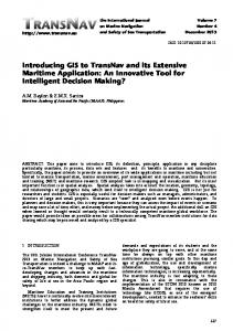
Figure 2. Phased Array Antenna and Base Station for SDMA Technique Courtesy of Manual: “Global Mobile CNS” by Ilcev [3]
Taking into account that within the systems of satellite communications, every user has own unique spatial position, this fact may be used for the separation of channels in space and as a consequence, to increase the SIR ratio by using SDMA. In effect, this method is physically making the separation of paths available for each satellite link. Terrestrial telecommunication networks can use separate cables
or radio links, but on a single satellite independent transmission paths are required. Thus, this MA control radiates energy into space and transmission can be on the same frequency: such as TDMA or CDMA and on different frequencies, such as FDMA.
5.1 Special Effects of SDMA in Wireless Systems The new technologies are recently implemented for the Third Generation Wireless (3G) with Future Enhancements. Some of the key enhancements to wireless technology include SDMA, the introduction of 3G wireless technologies and integration with personal and mobile applications including aeronautical. The SDMA method is a special system access technology that allows a single transmitter location to provide multiple communication channels by dividing the radio coverage into focused radio beams that reuse the same frequency. To allow multiple accesses, each mobile radio is assigned to a focused radio beam. These radio beams may dynamically change with the location of the mobile radio. Analogously, in reception, the mobile antenna picks up signals coming from all directions, including noise and interference. These considerations have lead to the development of the SDMA technique, which is based on deriving and exploiting information on the spatial position of mobile terminals. The use of an adaptive antenna array at the base station thus allows to introduce the SDMA technique, whose main advantage is the capability to increase system capacity, i.e. the number of users it can handle. This increase can be obtained in two different ways, and therefore the following applications are possible: 1 Reduction in Co‐channel Interference – The reduction in the level of co‐channel interference between the different cells using the same group of radio channels is obtained, as above seen, by minimizing the gain in the direction of interfering mobile units. This technique, indicated with the acronym Spatial Filtering for Interference Reduction (SFIR) allows to reduce frequency re‐ use distance and cluster size. In this way, each cell can be assigned a higher number of channels by phase array antenna, as presented in Figure 2 (A). 2 Spatial Orthogonality – In conventional access techniques, orthogonality between signals associated with different users is obtained by transmitting them in different frequency bands of FDMA, in different time slots of TDMA or using different code sequences of CDMA. Using an antenna array, it is possible to create an additional degree of orthogonality between signals transmitted to and from different directions. It is thus possible to assign the same physical channel to several mobile units, as depicted in Figure 22 (B), when the angles at which they are seen by the base station are sufficiently separated. The result is an increase in the number of available channels, since the same physical channel, for example the same carrier in a FDMA or the same time slot in a TDMA system, can be subdivided into multiple spatial channels, each of which is assigned to a different user. So, the multiple users belonging to the same cell use the same channel.
5.2 Special Effects of SDMA in Mobile Radio Systems In a FDMA mobile radio system, however capacity is limited by two different factors. On one hand, a limited number of radio channels, carriers and time slots, are available, and they must be subdivided among beams making up a cluster. On the other hand, co‐channel interference limits channel re‐use. The SDMA technique allows to expand both these limits and to enhance system capacity.
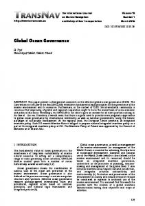
Figure 3. Hypothetical Scenario of SDMA for Mobile Radio Applications Courtesy of Manual: “Global Mobile CNS” by Ilcev [3]
As already described, this can occur in two different ways: with the SFIR technique and spatial orthogonality. In such a way, interference level is reduced and channel re‐use distance is decreased, whereas the actual SDMA technique assigns the same channel to multiple, spatially separated users. In Figure 3 is illustrated a SDMA system, which diagram shows a single tower that is serving many different users from the same radio tower on the same frequency using independent beams of radio energy. In practice this is not possible to achieve, because each type of mobile system has different frequency band, but they can be seen in separate way. On the other hand, the SDMA technique requires an array composed of more antennas than the SFIR technique does. In fact, spatial orthogonality is exploited by eliminating, through the use of spatial filtering, intra‐ cell co‐channel interference, which is Differently to say, in traditional radio systems the base station, having no information on the position of mobile units, is forced to radiate the signal in all direction, in order to cover the entire area of the cell. This entails both a waste of power and the transmission, in the directions where there are no mobile terminals to reach, of a signal which will be seen as interfering for co‐channel cells, i.e. those cells using the same group of radio channels. It must be noted that the term SDMA refers, strictly speaking, only to the latter application, in which SDMA is actually accomplished. In spite of this fact, the SFIR technique is also considered within the SDMA technique, since it is based on the same principles. In addition to the opportunity to increase system capacity, the SDMA technique has additional characteristics making its introduction in a mobile radio system advantageous. In particular, it is possible to exploit the higher receive gain offered by an antenna array with respect to an omnidirectional case, to allow mobile units to transmit at reduced power, and therefore lower consumption. At equal power, gain can be exploited to extend beam size. This is useful when it is necessary to cover vast surface areas, typically rural areas, characterized by a 535
low mobile radio traffic density, with a limited number of base stations [01, 03, 06, 12].
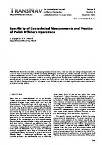
Figure 4. SDMA for Mobile Satellite Applications Courtesy of Manual: “Global Mobile CNS” by Ilcev [3]
Figure 5. The Beam Patterns and Adaptive Antenna Applications for SDMA Courtesy of Paper: “Smart Antenna Application for Satellite Communications with SDMA” by Zaharov [12]
5.3 Special Effects of SDMA in Mobile Satellite Systems The SDMA technology has been successfully used in satellite communications for several years. As stated, the SDMA technique can also be integrated with all the different MA techniques in use, such as FDMA, TDMA and CDMA, and therefore can be applied to any mobile communication system. However, we shall see that the ways in which the SDMA technique can be introduced and the advantages it provides differ depending on the system under consideration. As aforesaid described, modifications required to realize the SDMA technique are limited to the satellite array, and thus do not involve mobile units. However, this allows to introduce this technique in existing mobile satellite systems, with no need to modify their characteristics. The ability to reject jammer of adaptive arrays can be ensured for performing SDMA mode where several mobiles are allowed to share the same classical access in a cell, leading to a capacity increase. In Figure 4 is illustrated this sharing with possibility through the use of adaptive beam forming and interference rejection on the satellite uplink and downlink communication for mobiles, which are located at different angular sectors. In using SDMA, either FDMA or TDMA are needed to allow LES to roam in the same satellite beam or for polarization to enter the repeater. Thus, the frequency reuse technique of same frequency is effectively a form of SDMA scheme, which depends upon achieving adequate beam‐to‐beam and 536
polarization isolation. Using this system reverse line means that interference may be a problem and the capacity of the battery is limited. On the other hand, a single satellite may achieve spatial separation by using beams with horizontal and vertical polarization or left‐hand and right‐hand circular polarization. This could allow two beams to cover the same Earth surface area, being separated by the polarization. Thus, the satellite could also have multiple beams using separate antennas or using a single antenna with multiple feeds. For multiple satellites, spatial separation can be achieved with orbital longitude or latitude and for intersatellite links, by using different planes. Except for frequency reuse, this system provides on‐board switching techniques, which, in turn, enhance channel capacity. Additionally, the use of narrow beams from the satellite allows the Earth station to operate with smaller antennas and so produce a higher power density per unit area for a given transmitter power. Therefore, through the careful use of polarization, beams (SDMA) or orthogonal (CDMA), the same spectrum may be reused several times, with limited interference among users. The more detailed benefits of an SDMA system include the following: 1 The number of cells required to cover a given area can be substantially reduced. 2 Interference from other systems and from users in other cells is significantly reduced. 3 The destructive effects of multipath signals, copies of the desired signal that have arrived at the antenna after bouncing from objects between the signal source and the antenna can often be mitigated. 4 Channel reuse patterns of the systems can be significantly tighter because the average interference resulting from co‐channel signals in other cells is markedly reduced. 5 Separate spatial channels can be created in each cell on the same conventional channel. In other words, intra‐cell reuse of conventional channels is possible. 6 The SDMA station radiates much less total power than a conventional station. One result is a reduction in network‐wide RF pollution. Another is a reduction in power amplifier size. 7 The direction of each spatial channel is known and can be used to accurately establish the position of the signal source. 8 The SDMA technique is compatible with almost any modulation method, bandwidth, or frequency band including GSM, PHP, DECT, IS‐54, IS‐95 and other formats. The SDMA solution can be implemented with a broad range of array geometry and antenna types. Another perspective of the realization of SDMA systems is the application of smart antenna arrays with different levels of intelligence consisting in the antenna array and digital processor. Since the frequency of transmission for satellite communications is high enough (mostly 6 or 14 GHz), that the dimensions of an array placed in orbit is commensurable with the dimensions of the parabolic antenna, is a necessary condition to put such systems into orbit.
Thus, the SDMA scheme mostly responds to the demands of LEO and MEO constellations, when the signals of users achieve the satellite antenna under different angles (±22o for the MEO). In this instance, ground level may be split into the number of zones of service coverage determined by switched multiple beam pattern lobes in different satellite detections, or by adaptive antenna separations, illustrated in Figure 5 (A). Thus, there are two different beam‐forming approaches in SDMA satellite communications: (1) The multiple spot beam antennas are the fundamental way of applying SDMA in large fixed and mobile satellite systems and (2) Adaptive array antennas dynamically adapt to the number of users.
5.4 Switched Spot Beam Antenna Switched Multi‐Beam Antennas are designed to track each subscriber of a given cell with an individual beam pattern as the target subscriber moves within the cell (spot). Therefore, it is possible to use array antennas and to create a group of overlapping beams that together result in omnidirectional coverage. This is the simplest technique comprising only a basic switching function between separate directive antennas or predefined beams of an array. Beam‐switching algorithms and RF signal‐ processing software are incorporated into smart antenna designs. For each call, software algorithms determine the beams that maintain the highest quality signal and the system continuously updates beam selection, ensuring that customers get optimal quality for the duration of their call. One might design overlapping beam patterns pointing in slightly different directions, similar to the ones shown in Figure 5 (A). Every so often, the system scans the outputs of each beam and selects the beam with the largest output power. The black cells reuse the frequencies currently assigned to the mobile terminals, so they are potential sources of interference. In fact, the use of a narrow beam reduces the number of interfering sources seen at the base station. Namely, as the mobile moves, the smart antenna system continuously monitors the signal quality to determine when a particular beam should be selected. Switched‐beam antennas are normally used only for the reception of signals, since there can be ambiguity in the system’s perception of the location of the received signal. In fact, these antennas give the best performance, usually in terms of received power but they also suppress interference arriving from directions away from the active antenna beam’s centre, because of the higher directivity, compared to a conventional antenna, some gain is achieved. In high‐interference areas, switched‐beam antennas are further limited since their pattern is fixed and they lack the ability to adaptively reject interference. Such an antenna will be easier to implement in existing cell structures than the more sophisticated adaptive arrays but it gives only limited improvement.
5.5 Adaptive Array Antenna Systems Adaptive Array Antenna Systems select one beam pattern for each user out of a number of preset fixed beam patterns, depending on the location of the subscribers. At all events, these systems continually monitor their coverage areas, attempting to adapt to their changing radio environment, which consists in (often mobile) users and interferers. Thus, in the simplest scenario, that of a single user and no interferers, the system adapts to the user’s motion by providing an effective antenna system pattern that follows the mobile user, always providing maximum gain in the user’s direction. The principle of SDMA with adaptive antenna system application is quite different from the beam‐forming approaches described in Figure 5 (B). The events processed in SDMA adaptive array antenna systems are as follows: 1 A “Snapshot”, or sample, is taken of the transmission signals coming from all of the antenna elements, converted into digital form and stored in memory. 2 The SDMA digital processor analyzes the sample to estimate the radio environment at this point, identifying users and interferers and their locations. 3 The processor calculates the combining strategy for the antenna signals that optimally recovers the user’s signals. With this strategy, each user’s signal is received with as much gain as possible and with the other users/interferers signals rejected as much as possible. 4 An analogous calculation is done to allow spatially selective transmission from the array. Each user’s signal is now effectively delivered through a separate spatial channel. 5 The system now has the ability to both transmit and receive information on each of the spatial channels, making them two‐way channels [01, 03, 08, 09, 12].
Figure 6. Block Diagram of SDMA/FDMA and SDMA/SS/FDMA‐SDMA/SS/TDMA Courtesy of Manual: “Global Mobile CNS” by Ilcev [3]
As a result, the SDMA adaptive array antenna system can create a number of two‐way spatial channels on a single conventional channel, be it frequency, time, or code. Of course, each of these spatial channels enjoys the full gain and interference rejection capabilities of the antenna array. In theory, an antenna array with (n) elements can support (n) spatial channels per conventional channel. In practice, the number is somewhat less because the received multipath signals, which can be combined to direct received signals, takes place. In addition, by using special algorithms and space diversity techniques, the radiation pattern can be adapted to receive multipath signals, which can be combined. Hence, these 537
techniques will maximize the SIR or Signal‐to‐ Interference and Noise Ratio (SINR).
5.6 SDMA/FDMA This modulation arrangement uses filters and fixed links within the satellite transceiver to route an incoming uplink frequency to a particular downlink transmission antenna, shown in Figure 6 (A). A basic configuration of fixed links may be set up using a switch that is selected only occasionally. Thus, an alternative solution allows the filter to be switched using a switch matrix, which is controlled by a command link. Because of the term SS (Switching Satellite) this scheme would be classified as SDMA/SS/FDMA, which block diagram is shown in Figure 6 (B). The satellite switches are changed only rarely, only when it is desired to reconfigure the satellite, to take account of possible traffic changes. The main disadvantage of this solution is the need for filters, which increase the mass of the payload.
5.7 SDMA/TDMA This solution is similar to the previously explained SDMA/SS/FDMA in that a switch system allows a TDMA receiver to be connected to a single beam. Switching again is only carried out when it is required to reconfigure the satellite. Under normal conditions, a link between beam pairs is maintained and operated under TDMA conditions. The utilization of time slots may be arranged on an organized or contention basis and switching is achieved by using the RF signal. Thus, on board processing is likely to be used in the future, allowing switching to take place by the utilization of baseband signals. The signal could be restored in quality and even stored to allow transmission in a new time slot in the outgoing TDMA frame. This scheme is providing up and downlinks for the later Intelsat VI spacecraft, known as SDMA/SS/TDMA, which block diagram is shown in Figure 6 (B). This MA is using to allow TDMA traffic from the uplink beams to be switched to downlink beams during the course of TDMA frame. At this point, the connection exists at a specific time for the burst duration within the frame time before the next connection is made, and so on.
5.8 SDMA/CDMA This arrangement allows access to a common frequency band and may be used to provide the MA to the satellite, when each stream is decoded on the satellite in order to obtain the destination addresses. Thus, on‐board circuitry must be capable of determining different destination addresses, which may arrive simultaneously, while also denying invalid users access to the downlink. However, on‐ board processors allow the CDMA bit stream to be retimed, regenerated and stored on the satellite. Because of this possibility the downlink CDMA configurations need not be the same as for uplink and the Earth link may thus, be optimized [01, 03, 08, 10]. 538
6 RANDOM DIVISION MULTIPLE ACCESS (RDMA) For data transmission, a bit stream may be sent continuously over an established channel without the need to provide addresses or unique words if the channel is not charred. In fact, where charring is implemented, data are sent in bursts, which thus, requires unique words or synchronization signals to enable time‐sharing with other users, to be affected in the division of channels. Each burst may consist in one or more packets comprising data from one or more sources that have been assembled over time, processed and made ready for transmission. However, this type of multiplex scheme is also known as Packet MA. Packet access can be used in special RDMA solutions, such as Aloha, where retransmission of blocked packets may be required. Random access can be achieved to the satellite link by contention and for that reason is called a contention access scheme. This type of access is well‐ suited to satellite networks containing a large number of stations, such as SES, where each station is required to transmit short randomly‐generated messages with long dead times between messages. The principle of RDMA is to permit the transmission of messages almost without restriction, in the form of limited duration bursts, which occupy all the bandwidth of the transmission channel. Therefore, in other words, this is MA with time division and random transmission and an attribute for the synonym Random Division Multiple Access is quite assessable. A user transmits a message irrespective of the fact that there may be other users equally in connection. The probability of collisions between bursts at the satellite is accepted, causing the data to be blocked from receipt by the Earth station. In case of collision, the destination Earth station receiver will be confronted with interference noise, which can compromise message identification and retransmission after a random delay period. The retransmissions can occur as many times as probably are carried out, using random time delays. Such a scheme implies that the transmitter vies for satellite resources on a per‐demand basis and no other transmitter is attempting to access the same resources during the transmission burst period, when an error‐ free transmission can occur. The types of random protocols are distinguished by the means provided to overcome this disadvantage, which performance is measured in terms of the throughput and the mean transmission delay. Throughput is the ratio of the volume of traffic delivered at the destination to the maximum capacity of the transmission channels. The transmission time, i.e., delay is a random variable. Its mean value indicates the mean time between the generation of a message and its correct reception by the destination station.
6.1 Aloha The most widely used contention access scheme is Aloha and its associated derivatives. This solution was developed in the late 1960s by the University of Hawaii and allows usage of small and inexpensive Earth stations (including SES) to communicate with a
minimum of protocols and no network supervision. This is the simplest mode of operation, which time‐ shares a single RF, divided among multiple users and consists in stations randomly accessing a particular resource that is used to transmit packets. When an Aloha station has something to transmit, it immediately sends a burst of data pulses and can detect whether its transmission has been correctly received at the satellite by either monitoring the retransmission from the satellite or by receiving an acknowledgement message from the receiving party. Should a collision with another transmitting station occur, resulting in the incorrect reception of a packet at the satellite, the transmitting station waits for a random period of time, prior to retransmitting the packet. Otherwise, a remote station (SES) uses Aloha to get a hub station (CES) terminal’s attention. Namely, the SES terminal sends a brief burst requesting a frequency or time slot assignment for the main transmission. Thus, once the assignment for SES is made, there is no further need for the Aloha channel, which becomes available for other stations to use. After that, the main transmissions are then made on the assigned channels. At the end, the Aloha channel might be used again to drop the main channel assignments after the transmission is completed. The advantages of Aloha are the lack of any centralized control, giving simple, low‐cost stations and the ability to transmit at any time, without having to consider other users. In the case where the user population is homogenous, so that the packet duration and message generation rate are constant, it can be shown that the traffic carried S (packet correctly interpreted by the receiver), as a function of total traffic G (original and retransmitted message) is given by the relation: S = G exp (– 2G) [packet/time slot]
(8)
where (S = transmission throughput) and (G) are expressed as a number of packets per time slot equal to the common packet duration. The Aloha protocol cannot exceed a throughput of 18% and the mean transmission time increases very rapidly as the traffic increases due to an increasing number of collisions and packet retransmissions. The Aloha mode is relatively inefficient with a maximum throughput of only 18.4% (1/2). However, this has to be counter‐ weight against the gains in simple network complexity, since no‐coordination or complex timing properties are required at the transmitting SES.
equal to the duration of both packets. At this point, this situation divides the probability of collision by two and the throughput becomes: S = G exp (– G) [packet/time slot]
(9)
This protocol enables collisions between new messages and retransmission to be avoided and increases the throughput of S‐Aloha in the order of 50–60% by introducing a frame structure, which permits the numbering of time slots. Each packet incorporates additional information indicating the slot number reserved for retransmission in case of collision. For the same value of utilization as basic Aloha, the time delay and probability of packet loss are both improved. The major disadvantages of S‐ Aloha are that more complex equipment in the Earth station is necessary, because of the timing requirement and because there are fixed time slots, customers with a small transmission requirement are wasting capacity by not using the time slot to its full availability.
6.3 Slot Reservation Aloha This solution of an extension for the slotted‐Aloha scheme allows time slots to be reserved for transmission by an Earth station. In general terms this mode of operation is termed a Packed Reserved Multiple Access (PRMA). Slot reservation basically takes two forms: 1 Implicit – When a station acquires a slot and successfully transmits, the slot is reserved for that station for as long as it takes the station to complete its transmission. The network controller then informs all stations on the network that the slot is available for contention once more. There is only the problem that a station with much data to transmit could block the system to other users. 2 Explicit – Every user station may send a request for the reservation of a time slot prior to transmission of data. A record of all time slot occupation and reservation requests is kept. Actually, a free time slot could be allocated on a priority basis. Some kind of control for the reservation of slots is necessary and this could be accomplished by a single or all stations being informed of slot occupancy and reservation requests [01, 03, 06, 08, 09, 11].
7 CONCLUSION 6.2 Slotted Aloha This form of Aloha or S‐Aloha, where the time domain is divided into slots equivalent to a single packet burst time; there will be no overlap, as is the case with ordinary Aloha. The transmissions from different stations are now synchronized in such a way that packets are located at the satellite in time slots defined by the network clocks and equal to the common packet duration. Hence, there cannot be partial collisions; every collision arises from complete superposition of packets. In effect, the timescale of collision is thus, reduced to the duration of a packet, whereas with the Aloha protocol, this timescale is
The performances and capacities of MMSC for CDMA, FDMA and TDMA/FDMA have been analyzed many years ago for an L/C‐band RF network with global coverage. For the particular MMSC systems under discussion and for the particular antenna configurations, both CDMA and FDMA offer similar performance, FDMA yielding slightly higher channel capacities at the design point and CDMA being slightly better at higher EIRP levels. As the MMSC system grows and the antenna beam size decreases, CDMA appears to be a very efficient MA system, because it is not limited by L‐band bandwidth 539
constraints. However, CDMA is wasteful in feederlink bandwidth, and the choice of a multiple access system must take all parameters into consideration, such as oscillator stability, interference rejection, system complexity etc. as well as system cost before deciding on a particular multiple access system. The communication satellites for MMSC provide multiple‐beam antennas and employ frequency reuse of the allocated L‐band frequency spectrum. It appears that despite the fact that FDMA and FDMA/TDMA are orthogonal systems, they nevertheless suffer from bandwidth limitations and sensitivity to interbeam interference in L‐band. The CDMA scheme is better at absorbing Doppler and multipath effects, and it permits higher rate coding, but it suffers from self‐jamming and from bandwidth constraints in the feederlink. In general, all three multiple access systems show similar performance. However, at the chosen design point for aggregate EIRP, number of beams, and allocated bandwidth, FDMA provides still the highest system channel capacity. Recently is developed SDMA as an advanced solution where all concerned SES terminals can share the same frequency at the same time within a separate space available for each link. On the other hand, the RDMA scheme is suitable for large number of users in MMSC, where all SES terminals share asynchronously the same transponder by randomly transmitting short burst or packet divisions. In addition is developed several mobile Aloha methods, which successfully increase the system throughout.
540
REFERENCES [01] Ilcev D. S., “Global Mobile Satellite Communications for Maritime, Land and Aeronautical Applications”, Book, Springer, Boston, 2005. [02] Freeman R.L., “Radio systems design for telecommunications (1‐100 GHz)”, John Wiley, Chichester, 1987. [03] Ilcev D. S., “Global Mobile Communication, Navigation and Surveillance (CNS)”, Manual, DUT, Durban 2011 [www.dut.ac.za/space_science]. [04] Solovev V.I. & Others, “Svyaz na more”, Sudostroenie, Leningrad, 1978. [05] Maral G. & Other, “Satellite Communications Systems”, Wiley, Chichester, 2009. [06] Susi A. & Others, “Multiple Access in Mobile Satellite Communications”, PSN, ASSI (Asosiasi Satelit Indonesia), Electro Online, 1999. [07] Group of Authors, “Handbook ‐ Mobile Satellite Service (MSS)”, ITU, Geneva, 2002. [08] Zhilin V.A., “Mezhdunarodnaya sputnikova sistema morskoy svyazi – Inmarsat”, Sudostroenie, Leningrad, 1988 [09] Ohmory S., Wakana. H & Kawase S., “Mobile Satellite Communications”, Artech House, Boston, 1998. [10] Venskauskas K.K., “Sistemi i sredstva radiosvyazi morskoy podvizhnoy sluzhbi”, Sudostroenie, Leningrad, 1986. [11] Maini A.K. & Agrawal V., “Satellite Technology ‐ Principles and Applications”, John Wiley, Chichester, 2007. [12] Zaharov V. & Others, “Smart Antenna Application for Satellite Communications with SDMA”, Journal of Radio Electronics, Moscow, 2001.