Assistant Professor, Department of ECE, K L University, Guntur, AP, India. 2. M.Tech -VLSI Students, Department of ECE, K L University, Guntur, AP, India. 3.
SUSRUTHA BABU SUKHAVASI, SUPARSHYA BABU SUKHAVASI, LAKSHMI NARAYANA THALLURI, S R SASTRY KALAVAKOLANU, HARIKISHORE K, FAZAL NOOR BHASHA / International Journal of Engineering Research and Applications (IJERA) ISSN: 2248-9622 www.ijera.com Vol. 2, Issue 2, Mar-Apr 2012, pp.884-889
IMPLEMENTATION OF NEW SLANT FOR EFFICIENT POWER SAVING IN DIGITAL DESIGN BY USING AUTOMATIC CLOCK GATING TECHNIQUE SUSRUTHA BABU SUKHAVASI1*, SUPARSHYA BABU SUKHAVASI1 LAKSHMI NARAYANA THALLURI 2, S R SASTRY KALAVAKOLANU 2 HARIKISHORE K3, FAZAL NOOR BHASHA3 1*. Assistant Professor, Department of ECE, K L University, Guntur, AP, India. 1. Assistant Professor, Department of ECE, K L University, Guntur, AP, India. 2. M.Tech -VLSI Students, Department of ECE, K L University, Guntur, AP, India. 3. Assistant Professor, Department of ECE, K L University, Guntur, AP, India.
Abstract-This paper describes about the design methodology for reducing router power consumption with the aid of RTL clock gating technique. It causes inactive clocked elements to have clock gating logic (automatically by using cadence tool) which reduces power consumption on those elements to zero when the values stored by those elements are not changing. This technique allows a variety of features such as easily configurable, automatically implemented clock gating which allows maximal reduction in power requirements with minimal designer involvement and software involvement. In this paper, source code was written in Verilog (Hardware Descriptive language) and it was synthesized in Xilinx 9.1i version, simulated in Modelsim 6.6 version and clock gating was applied by using Cadence.
Index Terms-Router, FSM, FIFO, Verilog, Clock
values. Clock gating technique can be introduced into a design manually or tools exist to perform clock gating automatically.
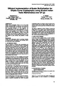
II. ROUTER SPECIFICATIONS In this paper a low power 1x3 Router was designed by considering the following specifications: A. Input/output Specifications The router accepts data packets on a single 8-bit port called data and routes the packets to one of the three output channels (channel0, channel1 or channel2). The router has an active low input resetn resets the router. data Channel0 Vld_chan_0 Packet_valid
Read_enb_0
Suspend_data_in
Gating, Low Power Digital Design. Err
Channel1
ROUTER
Vld_chan_1
I. INTRODUCTION The demand for low power circuit design has increased significantly due to the explosive growth of battery-operated portable applications like laptop computers and cellular Phones. The mandate to reduce system power consumption and design energy-efficient ICs has led to the increasing use of low-power IC design techniques. In order to reduce power consumption, clock gating is a useful technique to reduce switching activities. Due to the dramatic increase in portable and battery-operated applications, lower power consumption has become a necessity in order to prolong battery life. Power consumption is an important part of the equation determining the end product's size, weight, and efficiency. In synchronous digital circuits the clock net is responsible for a significant part of the power dissipation. Clock gating tries to reduce the activity on parts of the clock net by disabling the clock on flip flops when they are clocked only to retain their
Read_enb_1 Clock
Channel2 Vld_chan_2
Resetn
Read_enb_2
Figure 1. Block diagram of 1x3 Router
B. Data packet Description Data packet is a sequence of bytes with the first byte containing a header, the next variable set of bytes containing data, and the last byte containing parity.
884 | P a g e
SUSRUTHA BABU SUKHAVASI, SUPARSHYA BABU SUKHAVASI, LAKSHMI NARAYANA THALLURI, S R SASTRY KALAVAKOLANU, HARIKISHORE K, FAZAL NOOR BHASHA / International Journal of Engineering Research and Applications (IJERA) ISSN: 2248-9622 www.ijera.com Vol. 2, Issue 2, Mar-Apr 2012, pp.884-890 7
6
5
4
3
2
1 0
Header
addr
Header
byte 0 byte 1
data [0] Payload
data [1]
byte N
data [N]
Parity
byte N+1 Parity
Figure 2. Data packet format
The header consists of a 2-bit address field and a 6-bit length field. The address field is used to determine to which output channel the packet should be routed, with address „3‟ being illegal. The length field specifies the number of data bytes (payload). A packet can have a minimum data size of 1 byte and maximum data of 63 bytes. The parity should be a byte of even, bitwise parity, calculated over the header and data bytes of the packet. C. Router Input Protocol All input signals are active high and are synchronized to the falling edge of the clock. Therefore, any signal that is an input to the DUV is driven at the falling edge of clock. This is because the DUV router is sensitive to the rising edge of clock. Therefore, driving input signals on the falling edge ensures adequate setup and hold time.
D. Router Output Protocol All output signals are active high and are synchronized to the falling edge of the clock. Thus, the packet receiver will drive sample data at the falling edge of the clock. This is correct because the router will drive and sample data at the edge of clock. Each output port channelX (channel0, channel1 or channel2) is internally buffered by a FIFO of depth and width of 1 byte. The router asserts the vld_chan_x (vld_chan_0, vld_chan_1 or vld_chan_2) signal when valid data appears on the channelX (channel0, channel1 or channel2) output bus. This is a signal to the packet receiver that valid data is available on a particular router. Clock Packet_ valid
data
Clock delay Packet_ valid data
The packet_valid signal has to be asserted on the same clock as when the first byte of a packet (the header byte), is driven onto the data bus. Since the header byte contains the address, this tells the router to which output channel the packet should be routed (channel0, channel1 or channel2). Each subsequent byte of data should be driven on the data bus with each new falling clock. After the last payload byte has been driven, on the next falling clock, the packet_valid signal must be deasserted, and the packet parity byte should be driven. This signals packet completion. The input data bus value cannot change while the suspended_data in signal is active (indicating a FIFO overflow). The packet driver should not send any more bytes and should hold the value on the data bus. The width of suspended_data_in signal assertion should not exceed 100 cycles. The err signal esserts when a packet with bad parity is detected in the router, within 1 to 10 cycles of packet completion.
H
D
D
D
P
H
D
D
D
P
Vld_ Channel0 chan_ 0 Received Read Packet _enb _0
H
D
D
D
P
H
D
D
P
Response delay
H Suspend _data_in
D
D
D
D
P
Packet (addr=0)
err Sent packet
Packet (addr=0)
Packet (addr=0)
H = Header, D = data, P = Parity
Figure 3. Router input protocol
Figure 4. Router output protocol The packet receiver will than wait until it has enough space to hold the byte of the packet and then respond with the asserts if the read_enb_x (read_enb_0, read_enb_1 or read_enb_2) signal that is an input to the router. The read_enb_x (read_enb_0, read_enb_1 or read_enb_2) input signal is asserted on the falling clock edge in which data are read from the channelx (channel0,channel1 or channel2) bus.
885 | P a g e
SUSRUTHA BABU SUKHAVASI, SUPARSHYA BABU SUKHAVASI, LAKSHMI NARAYANA THALLURI, S R SASTRY KALAVAKOLANU, HARIKISHORE K, FAZAL NOOR BHASHA / International Journal of Engineering Research and Applications (IJERA) ISSN: 2248-9622 www.ijera.com Vol. 2, Issue 2, Mar-Apr 2012, pp.884-890 As long as the read_enb_x (read_enb_0, read_enb_1 or read_enb_2) signal remains active, the channelX (channel0, channel1 or channel2) bus drives a valid packet byte on each rising clock edge. The packet receiver cannot require the router to suspend data transmission in the middle of the packet. Therefore, the packet receiver must assert the read_enb_x (read_enb_0, read_enb_1 or read_enb_2) signal only after it ensures that there is adequate space to hold the entire packet. The read_enb_x (read_enb_0, read_enb_1 or read_enb_2) must be asserted within 30 clock cycles of the vld_chan_x (vld_chan_0, vld_chan_1 or vld_chan_2) being asserted. Otherwise, there is too much congestion in the packet receiver. The DUV channel (channel0, channel1 or channel2) bus must not be tri-stated when the DUV signal vld_chan_x (vld_chan_0, vld_chan_1 or vld_chan_2) is asserted and the input signal read_enb_x (read_enb_0, read_enb_1 or read_enb_2) is also asserted high.
III. ROUTER DESIGN Switches and routers are the critical building blocks of a successful network infrastructure, to route the data in the network. In the design of a low power network the blocks like router must consume less power. In the semiconductor and electronic design industry, Verilog is a HDL used to model electronic systems. Verilog HDL allows designers to design at various levels of abstraction. In this paper, a low power 1x3 router was designed by applying clock gating to the router RTL code. The low power digital design flow was as shown in figure 5. In this paper, the 1x3 router consist of two main modules one is FSM and another is FIFO. Design specification
Behavioral description
RTL description
No Verification Vectors
RTL Functional Verification
Yes
Figure 5. Low power digital design flow
Chip Production
Clock Gating
A. FSM Design Basically a FSM consists of combinational, sequential and output logic. Combinational logic is used to decide the next state of the FSM. Sequential logic is used to store the current state of the FSM. By considering the session II router specifications the router was designed, at the input side an eight state FSM receives the data and transmit that data to the output channels (channel0, channel1 or channel2). The eight states are IDEAL, ADDR_CHECK, CH0, CH1, CH2, HOLD, PARITY_LOADER and PARITY_CHECK. When there is valid input data then FSM goes to next state i.e. ADDR_CHECK otherwise it will be in the IDEAL state. In the ADDR_CHECK FSM checks the address bits, if the address bits are „00‟ then the next stale is CH0, if the address bits are „01‟ then the next state is CH1, if the address bits are „10‟ then the next state is CH2 otherwise IDEAL is the next state. In CH0 state, if the channel is full or empty then the net state is HOLD, if it not satisfied the packet valid is zero then the next stage is PARITY_LOADER otherwise it continues in the previous state. Similarly CH1 and CH2 are executes. In the HOLD state, based on the full signal bits the next state will be CH0, CH1, CH2, IDEAL or it will continue in the hold state. In the PARITY_CHECK, if the par bit is 1 and the parity and parity2 are equal then the next state is HOLD, where par is an intermediate signal. B. FIFO design An 8-bit width FIFO is designed, because the 1x3 router has three output channels. At the output side parallel placing of three FIFO‟s will work as three output channels, and the channel was selected automatically by considering the address bits. C. Clock Gating Clock gating is a popular technique used in many synchronous circuits to reduce dynamic power dissipation. Clock gating saves power by adding more logic to a circuit to prune the clock tree. Pruning the clock disables portions of the circuitry so that the flip-flops in them do not have to switch states. Switching states consumes power. When not being switched, the switching power consumption goes to zero, and only leakage currents are incurred. Cadence, Synopsys like tools will apply clock gating to the RTL code automatically. So, in this paper the clock gating was applied to the router RTL Verilog code by using cadence, the dynamic power is reduced more than 65%. But the number of cells count was increased; because of placing of clock gating cells throughout the clock tree due to this the area is also increasing.
HDL Synthesis
Design Implementation
886 | P a g e
SUSRUTHA BABU SUKHAVASI, SUPARSHYA BABU SUKHAVASI, LAKSHMI NARAYANA THALLURI, S R SASTRY KALAVAKOLANU, HARIKISHORE K, FAZAL NOOR BHASHA / International Journal of Engineering Research and Applications (IJERA) ISSN: 2248-9622 www.ijera.com Vol. 2, Issue 2, Mar-Apr 2012, pp.884-890
Figure 8. Top Module Of FIFO
IV. SIMULATION AND POWER ANALYSIS Simulation refers to the verification of a design, its function and performance. It is process of applying stimuli to a model over time and producing corresponding responses from a model. Figure 10 represents the simulation of input channel, output channel and router using Modelsim 6.6 version. Synthesis process converts user‟s hardware description into structural logic description. It provides a means to covert schematics of HDL into real world hardware. Synthesis tools convert the described hardware into a net list that a vendor may use to create a chip or board. Figure 7, Figure 8 and Figure 9 represents the synthesis of Router, Top module of FIFO, Top module of FSM and using Xilinx 9.1i version. The easy and popular system-level clock-gating stops the clock for an entire Router, effectively disabling all functionality. It prevents the logic from switching. The power reports without clock gating [Figure 11] and with clock gating [Figure12] generated by using cadence tool, the total power was reduced more than 65%.
Figure 9. Top module of FSM
Figure 10. Router simulation report
Figure 7. Router RTL schematic
887 | P a g e
SUSRUTHA BABU SUKHAVASI, SUPARSHYA BABU SUKHAVASI, LAKSHMI NARAYANA THALLURI, S R SASTRY KALAVAKOLANU, HARIKISHORE K, FAZAL NOOR BHASHA / International Journal of Engineering Research and Applications (IJERA) ISSN: 2248-9622 www.ijera.com Vol. 2, Issue 2, Mar-Apr 2012, pp.884-890
Figure 11. Power report without clock gating
[3] E.Tellez, A. Farrah and M. Sarrafzadeh, “Activitydriven clock design for low power circuits,” in Proc.IEEE ICCAD, San Jose, pp.62-65, Nov. 1995. [4] V.G.Oklobdzija, V.M.Stojanovic, D.M.Markovic, N. M. Nedovic: Digital System Clocking: HighPerformance and Low-Power Aspects, 1st Ed. Wiley IEEE-press (2003). [5] Q. Wu, M. Pedram, and X. Wu, “Clock-gating and its application to low power design of sequential circuits,” IEEE Trans. Circuits Syst. I, Reg. Papers, vol. 47, no. 3, pp. 415–420, Mar. 2000. [6] J. Chueh, C. Ziesler, and M. Papaefthymiou, “Empirical evaluation of timing and power in resonant clock distribution,” in Proc. IEEE Int. Symp. Circuits Syst., May 2004, vol. 2, pp. 249–252. Susrutha Babu Sukhavasi was born in India, A.P. He received the B.Tech degree from JNTU, A.P, and M.Tech degree from SRM University, Chennai, Tamil Nadu, India in 2008 and 2010 respectively. He worked as Assistant Professor in Electronics & Communications Engineering in Bapatla Engineering College for academic year 20102011 and from 2011 to till date working in K L University. He is a member of Indian Society For Technical Education and
Figure 12. Power report with clock gating
CONCLUSION In this paper, a low power and high performance 1x3 router was designed by using the dynamic power reduction technique i.e. clock gating. After applying the clock gating to the router RTL Verilog code by using cadence tool, the dynamic power was reduced more than 65%, but the area was increased, because the insertion of clock gating cells throughout the clock tree.
ACKNOWLEDGMENT The authors would like to thank V S P K Aditya Majji, ASIC Verification Engineer at Perfectus Technology for many helpful suggestions.
REFERENCES [1] Benini, L., and G. De Micheli, “Automatic Synthesis of low-Power Gated-Clock FiniteState-machines”, IEEE Transactions on ComputerAided Design of Integrated Circuits and System, 15(6), 630-643 (June, 1996). [2] M.Pedram, “Power minimization in IC Design: Principles and applications,” ACM Transactions on Design Automation, vol. 1, no. 1, pp.3-56, Jan. 1996.
International Association of Engineers. His research interests include Mixed and Analog VLSI Design, FPGA Implementation, Low Power Design and wireless Communications, Digital VLSI. Suparshya Babu Sukhavasi was born in India, A.P. He received the B.Tech degree from JNTU, A.P, and M.Tech degree from SRM University, Chennai, Tamil Nadu, and India in 2008 and 2010 respectively. He worked as Assistant Professor in Electronics & Communications Engineering in Bapatla Engineering College for academic year 20102011 and from 2011 to till date working in K L University. He is a member of Indian Society For Technical Education and
International Association of Engineers. His research interests include Mixed and Analog VLSI Design, FPGA Implementation, Low Power Design and Wireless communications, VLSI in Robotics. Lakshmi Narayana Thalluri received the B.Tech. degree in Electronics & Communications Engineering from JNTU, Kakinada in 2009 and pursuing M.Tech (VLSI) in K L University. He is a member of International Association of Computer Science and Information Technology (IACSIT). His research interests include Analog VLSI Design, Digital VLSI Design 888 | P a g e and Low Power VLSI Design.
SUSRUTHA BABU SUKHAVASI, SUPARSHYA BABU SUKHAVASI, LAKSHMI NARAYANA THALLURI, S R SASTRY KALAVAKOLANU, HARIKISHORE K, FAZAL NOOR BHASHA / International Journal of Engineering Research and Applications (IJERA) ISSN: 2248-9622 www.ijera.com Vol. 2, Issue 2, Mar-Apr 2012, pp.884-890 S R SASTRY KALAVAKOLANU was born in A.P,India. He received the B.Tech degree in Electronics & communications Engineering from Jawaharlal Nehru Technological University in 2010. Presently he is pursuing M.Tech VLSI Design in KL University. His research interests include Low Power VLSI Design.
Harikishore Kakarla was born in Vijayawada, Krishna (Dist.), AP, India. He received B.Tech. in Electronics & Communication Engineering from, JNTU, Hyderabad, AP, India, MTech from SKD University,Anantapur,AP, India. He is pursuing Ph.D in the area of VLSI in KL University, Vijayawada, AP, India. Presently, he is working as a Assistant Professor, Department of Electronics and Communication Engineering, KL University, Guntur, Andhra Pradesh, India, where he has been engaged in teaching, research and development of High-speed CMOS VLSI SoC, Memory Processors LSI‟s, Fault Testing in VLSI, Embedded Systems and Nanotechnology. He is a Life Member of Indian Society for Technical Education (MISTE). He has published 08 International Journals and 01 National Conference Level.
Fazal Noorbasha was born on 29th April 1982. He received his, B.Sc. Degree in Electronics Sciences from BCAS College, Bapatla, Guntur, A.P., Affiliated to the Acharya Nagarjuna University, Guntur, Andhra Pradesh, India, in 2003, M.Sc. Degree in Electronics Sciences from the Dr. HariSingh Gour University, Sagar, Madhya Pradesh, India, in 2006, M.Tech. Degree in VLSI Technology, from the North Maharashtra University, Jalgaon, Maharashtra, INDIA in 2008, and Ph.D. Degree in VLSI from Department Of Physics and Electronics, Dr. HariSingh Gour Central University, Sagar, Madhya Pradesh, India, in 2011. Presently he is working as a Assistant Professor, Department of Electronics and Communication Engineering, KL University, Guntur, Andhra Pradesh, India, where he has been engaged in teaching, research and development of Lowpower, High-speed CMOS VLSI SoC, Memory Processors LSI‟s, Fault Testing in VLSI, Embedded Systems and Nanotechnology.
889 | P a g e