of a software solution for fast reconfiguration of a Virtual private. LAN service ... for two or more customers sites is provisioned with the Service. Access Point ...
International Journal of Engineering and Advanced Technology (IJEAT) ISSN: 2249 – 8958, Volume-2, Issue-5, June 2013
Implementation of Software for VPLS Service Reconfiguration Anil Kumar G, P Jayarekha, Krishna Kumar M, H S Guruprasad Abstract— This paper focus on the design and implementation of a software solution for fast reconfiguration of a Virtual private LAN service (VPLS) service for a business enterprise in the MPLS VPN network. The VPLS service as is a transparent LAN service for two or more customers sites is provisioned with the Service Access Point (SAP), Service Distribution Point (SDP) and Pseudo wire configurations with a per service granular QoS. The paper also pronounces the fast user customization of the service which reflects in the service manager. Each service in the service router has a unique ID. The reconfiguration is done based on the specifications provided by the customer. The flexibility of reconfiguration and customization criteria is met by the software tool which acts as a black box, taking the service IDs of the VPN services and provides scalability in accessing the configurations of large number of services and providing LOG files which associate to minimize the reconfiguration time of the VPN service. At the end, an example VPLS service is shown with the actual and desired service configurations and also the features of the software tool along with the design, implementation consisting of various modules the project is divided in and the procedures used with the test results provided. Index Terms— MPLS/VPN, Reconfiguration, SAP, SDP, VPLS.
I. INTRODUCTION Due to the robustness of MPLS network, technology has been widely gaining attention and the use of MPLS VPN at the same time, VPLS is traditional MPLS L2 VPN scheme based on development, and it can realize more to the multipoint VPN network. It inherits MPLS VPN Ethernet and advantages, providing a more complete solution, and has a broad market prospect. In essence to meet the growing demand for bandwidth to attain the customer and enterprise need for services like VPLS, VLL, SCADA, Voice services, IPX, VoIP etc. there is a need for fast configurations of the services in the service router in accord to the customer specifications. Whenever a service is initiated, the router is fed with generalized service configurations. This generalized configuration has to be changed to specific configuration provided by the customer. Every service in the service Router has to be checked for the mismatched configurations of the actual and customer specified configurations and has to be modified accordingly. Hence there is an overhead of manually verifying the service configurations of both the files, which is time consuming and also cumbersome when the VPN services are huge in number.
Manuscript received on June, 2013 Anil Kumar G, M.Tech (CNE), IV Semester, BMSCE, Basavanagudi, Bangalore, India. Dr. P Jayarekha, Associate Professor, Dept. of ISE, BMSCE, Basavanagudi, Bangalore, India. Krishna Kumar M, Senior Technical Specialist, Alcatel Lucent India. Dr. H S Guruprasad, Professor and Head of the Department, Dept. of ISE, BMSCE, Basavanagudi, Bangalore, India.
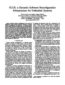
In the previous paper [1] we have discussed a methodology of eliminating the incurred overhead by means of a scalable software solution which intelligently spots out the differences in the configurations by providing log files which present enough information to reconfigure the router in according to the customer description of a VPN service. In this paper the design and implementation details of the software with the procedures adopted and modules in which it is divided into are being presented. II. OVERVIEW OF MPLS MPLS is a light weight tunneling technology, used in many service provider networks. The IP/MPLS VPN is an MPLS switching-enabled, service-oriented IP routed VP network. A tunnel or a LSP is created by the contagious set of routers in the MPLS network, that distributes a set of fixed length 32 bit labels running from network’s ingress (entry point) to network’s egress(exit point)[2]. In the MPLS network, the router at the ingress will append a label to the packets entering the LSP, the intermediate routers swap the label and the router at the egress will dispose the label and sends the packets on their way [3]. It uses a simple label-swap forwarding procedure to switch packets over the network. As an inference the service providers can reach a large number of enterprise and residential customers for VPN services. This kind of network must provide IP-routing protocols including scalable interior gateway, BGP and also support traffic engineering. Support the deployment of service based QoS, accounting and security policies [4]. Implementation of QoS must be service oriented and has to provide granularity per service management, sharing the same physical equipment. This kind of implementation attracts the customers longing to reduce technical support costs. A. Benefits of MPLS VPN Offers an easy management of VPN members Fast Creation of new VPNs Fast deployment platform of value added services including voice, multimedia etc. Network based VPN can be easily operated by service providers and can be implemented in the network B. Components of MPLS Network Fig.1 shows the various components in the core of an MPLS network Provider Edge (PE): Directly connected with the users, in which all the intelligence of VPN services is implemented [4]. Allows provisioning each service instance. Receives traffic from the customers, appends a label and sends on to the LSP. Provider (P): The P Routers consists of the bulk of the Backbone network, which are not aware of any VPN service instances. In MPLS, the P routers are called LSR (Label Switch Router) [4].
495
Implementation of Software for VPLS Service Reconfiguration instances and do not exchange traffic. As an important part of any Ethernet bridged network, VPLS supports VLAN trucking, double tagging (Q-in-Q), and VLAN translation [10]. Fig. 2 shows the emulated LAN provided by the MPLS/VPN VPLS network connecting multi point sites PE1, PE2, PE3.
Fig.1. MPLS Reference architecture
Customer Edge (CE): Users connected directly with service providers Site at the Edge of the equipment. These devices exchange the traffic with the network in a native format. Access links (AC): Attachment is the connection between the CE to PE link or virtual link [4]. Tunnel (Tunnels): used for carrying Pseudo Wires. A tunnel can carry on the multiple PW, normally for MPLS tunnel [4]. III. LAYER 2 SERVICES Two prominent services are defined in layer 2 which provide point to point and point to multi point. Services providing point to multi point or multi point to multipoint connectivity are called VPLS services and those providing point to point connectivity are called Virtual Leased Line Services. A. VPLS service VPLS is an emerging layer 2 MPLS based services standard that provides multipoint Ethernet Transparent LAN Service (TLS) [3] to enterprise users. VPLS combines Ethernet technology and technical advantages of MPLS VPN, Ethernet switching etc. The VPLS customers are not all connected to a single LAN, the customers may be spread across a metropolitan or wide area. In essence, a VPLS glues several individual LANs across a packet-switched network provided by scalable-shared IP/MPLS to appear (virtual connection) and function as a single LAN. VPLS can also inter-work with ATM and Frame Relay networks [11]. It is transparent to routing protocols. MPLS can provide Traffic Engineering (TE) functionality, which includes the QoS guarantees [11], resources optimization, and fast failure recovery. Each service router has a VPLS service instance (also referred as a Virtual Switching Instance, or VSI) [10]. Each VSI performs MAC address learning and constructs a table that maps MAC addresses to the corresponding MPLS paths (pseudo wires) [10] or the customer access ports. By using VPLS services, customers can significantly expand the coverage of their private LAN while keeping the routing control to themselves. It is an ideal solution for non-IP protocols (e.g., Interwork Packet Exchange, IPX) within a campus [4]. VPLS service instances are provisioned in the customer facing service routers involved in the service, and multiple services in the same router are isolated by the service
Fig.2. MPLS/VPN VPLS, multipoint service B. Virtual Leased Line service A Virtual Leased Line (VLL) is a Layer 2 VPN [10]. A VLL is analogous to a private line within the MPLS enterprise infrastructure. It offers a point-to-point connection between any two end-users, applications, or devices. A VLL can be used for applications that require dedicated point-to-point connectivity. In each VLL, two customer sites are connected by the VLL service provided by the two service routers. Each service router has a VLL service instance provisioned on it. The two service instances belonging to the same VLL service at the two service routers are connected by a pseudo wire (PW) [10] over the IP/MPLS core network. The VLL is the simplest type of VPN to deploy with least resource consumption. The VLL is completely transparent to the end-user data and application protocol. Many mobile operators deploy VLL services in their IP/MPLS backbone networks to backhaul the mobile traffic [10] while implementing new IP-based data applications to provide more types of services to their subscribers. Fig.3 shows a simple topology of a point to point virtual leased line connecting the provider edges PE1 and PE2 with a pseudo wire.
Fig.3. MPLS/VPN VLL, point to point service IV. METHODOLOGY OF VPLS SERVICE CREATION A service is a unique entity that refers to a type of connectivity service for either Internet or VPN connection [5]. Each service is uniquely identified by a service ID within a service area. The service model implemented in the Routers in the IP/MPLS network uses logical service entities to construct a service.
496
International Journal of Engineering and Advanced Technology (IJEAT) ISSN: 2249 – 8958, Volume-2, Issue-5, June 2013 The basic logical entities in the service model used to construct a VPN service are: Customers Service Access Points (SAPs) Service Distribution Points (SDPs).
Table I
A. Customers The most basic required entity is the customer ID value which is assigned when the customer account is created. B. Service Access Points (SAP) Each subscriber service type is configured with at least one service access point (SAP) [5]. A SAP identifies the customer interface point for a service on Service Router. C. Service Distribution Points (SDP) A service distribution point (SDP) acts as a logical way to direct traffic from one Router to another Router through a unidirectional (one-way) service tunnel [5]. The SDP terminates at the far-end Router which directs packets to the correct service egress SAPs on that device. A distributed service consists of a configuration with at least one SAP on a local node, one SAP on a remote node, and an SDP binding the service to the service tunnel.
F. Design Considerations/Features A tool to telnet to a service router and access multiple service configuration files. The tool works in a combination of m*n*o, where m = routers, n = service IDs, o = commands to the service Router. The tool takes the actual and desired configuration files of a VPN service and intelligently spot out the differences, taking enough care of the misalignment and mismatch of the configuration lines. An additional intelligence is built to filter out the configuration lines that have to be identical in both the files.
D. VPLS service Creation between two service sites As shown in Fig.4, VPLS service is created, that runs across two sites by providing necessary parameters to SAP, SDP and pseudo wire. The configurations of a service in the service router reflect the logical interpretation of the service between two sites.
V. IMPLEMENTATION
Fig.4. Creation of VPLS service between two sites. Table 1 gives an example of actual and customer specified VPLS ingress service configuration [12]. It can be seen that some of the configurations do not match in each of the configuration segments. E. Requirement of software solution for fast reconfiguration of a Service With the increasing volume of the services to the various enterprise customers, the service provider encounters difficulty in using the traditional way approach of manual reconfiguration. Hence there lies a requirement for a software solution for the same
The process of reconfiguration includes testing the actual and the desired configuration files for the difference. A lot of difference lies in the mismatch of the values of the customer configurable values as shown in the Table I. More over the desired configuration file may contain some lines that are not present in the actual configuration file or vice versa. The service provider has to identify these differences and reconfigure the service according to the customer need. This software intends to identify those differences taking care of the customer configurable values, mismatched and missing configuration lines. The design of the software consists of four modules Automated Telnet Reconstruction of Actual Configurations Intelligent compare. Post processor. Fig.5. shows the block diagram of the operations performed while addressing to the fast reconfiguration issue. A. Automated Telnet In this module, a perl script works at the back end to telnet to a Service Router automatically and fetch the service configuration stored. The script works as a black box taking a text file cosisting of the IP address of the various service routers and corresponding ID’s of the services on it as input, and giving service configurations written to a text file as output. The number of text files in the output are equal to the number IP address and service ID pairs given as input.
497
Implementation of Software for VPLS Service Reconfiguration criteria, which are then fed to the intelligent compare along with the customer desired configuration Fig.7 shows the telnet to a service router which retrieves the service configurations of various services in one go.
Fig.5. Software solution for reconfiguration Table II shows the sample input pairs of the type VPLS to the software tool. Table II
Fig. 7.Experiment conducted to Telnet to various service routers to retrieve the service configurations (Routers*service IDs*Commands).
Fig.6. shows the flowchart of the procedure used in the implementation of automated telnet tool. The input is given through the file “F”.
Fig.6. Procedure for Automated telnet. The command to be executed on th service router depends on the type of the service. Ex: VPLS, VPRN. Provision is made for the tester to customize the selection of executable commands. The command to fetch the VPLS service configuration with a given service ID of 5000 is ->configure->service->VPLS->5000-> info. The automated telnet retrieves the configuration of various services on the service router addressing to the scalability
B. Reconstruction of actual configuration file. Although both the actual and desired configuration files to be included for the test are locally present, they cannot be compared directly. The values of the customer configurable variables [12] in the actual config file are to be replaced by the corresponding values in the desired file. In this module a suitable method is implemented for the same. Ex : scheduler-override scheduler "AF1-Traffic" create rate 1000 [User entered VPN speed] In the above example, rate is a customer configurable variable [12] and the value 1000 is provided by the customer. Such variables in the cofiguration file are identified and written to another file called “Filter”. The values of those variables in the actual config file are replaced by the corresponding values in the desired config file. C. Intelligent Compare The intelligent compare provides LOG files which provides helpful statistics or information on addressing to the minimization of reconfiguration time. The module is developed using C programming language. Fig.8 shows the implemented procedure for the comparison of configuration files. The actual configurations are stored in the “File1” and the desired configurations in the “File2”. The user configurable values are stored in the “Filter”. The prerequisite to the file mapping is that actual config file is reconstructed in the module two. All the entries in the file “Filter” are ignored from comparison. Each configuration line read from the File1 is matched with the line read from the file Filter. If match occurs, then the line is skipped from comparison else the line is compared with the configuration line read from the file File2. If they do not match then the configuration line is written to the log file along with the line number. This log file is called the mismatch log as shown in the Table III, since only the config lines that do not match from both the files logged.
498
International Journal of Engineering and Advanced Technology (IJEAT) ISSN: 2249 – 8958, Volume-2, Issue-5, June 2013 the design, procedures and modules used in implementation of one such software solution that will benefit the service provider or the tester to reconfigure the service descriptions, meeting the time constraints by providing corrections to be made in the form of logs. As a result, the job of tester in reconfiguring a service is greatly reduced. It is up to the service provider to interpret the changes to be made to the service router based on the information provided in the logs. The software tool can also be enhanced to eliminate the interference of service provider in reconfiguration of a service and the system can be made more autonomous. ACKNOWLEDGMENT I am thankful to Alcatel-Lucent, Bangalore and my mentor Krishna Kumar M, for his constant encouragement, guidance and support since beginning, which has transformed me as a “Subject Matter Expert”. Last but not least, I would like to extend my gratitude to all those who indirectly supported me for the success of this paper. REFERENCES [1]
Fig.8. Procedure for Intelligent compare. D. Post compare The log file generated in the previous module consists of the configuration lines that are mismatched. The drawback of this log file is that if a line in the middle of the file is mismatched then all the successive lines will be mismatched. To avoid this, the two files i.e. “File1” and “File2” are again tested to identify the configuration lines that are really missing from the actual file and causing the mismatch. In this module, it is ensured that the frequency of all the unique lines in “File1” is same as the frequency in “File2”. This test gives second LOG file which consists of only the lines that are missing from the actual configuration file. Table III
As a result, the software provides two LOG files, mismatched LOG and missing LOG, providing only those configurations lines which are to be focused on and corrected, rather than manually reconstructing the actual configuration file, comparing each and every line checking for correctness.
Anil kumar G, Krishna Kumar M, Dr. P Jayarekha, "Software solution for fast Reconfiguration of VPLS services," National Conference on Wireless Communication, Signal Processing, Embedded Systems, WiSE 2013. [2] Brian Daugherty and Chris Metz, “Multiprotocol Label Switching and IP, LS VPNs over IP Tunnels,” IEEE INTERNET COMPUTING, JUNE 2005. [3] Besnik Shatri,Agim Abdullahu, Skënder Rugova,Arianit Maraj, “VPN creation in IP/MPLS Network in Kosova,” Seventh International Conference on Networking, 2008 IEEE. [4] Zhuo (Frank) Xu Alcatel - Lucent SRA No. 1, “Designing and Implementing IP/MPLS-Based Ethernet Layer 2 VPN Services”, An Advanced Guide for VPLS and VLL. [5] Jiezhao Peng, “VPLS Technology Research and Application in the Architectures of E-Government Network,” International Conference on Management of e-Commerce and e-Government, 2009 IEEE. [6] Giuseppe Di Battista, Massimo Rimondini, Giorgio Sadolfo, “Monitoring the Status of MPLS VPN and VPLS Based on BGP Signaling Information,” IEEE Network Operations and Management Symposium (NOMS), 2012. [7] Shivanagouda Biradar, Basel Alawieh and Hussein Mouftah, “Delivering Reliable Real-Time multicast Servicesover Virtual Private LAN Service,” IEEE ICC, 2006 IEEE. [8] Byeongsik Kim, Seunghyun Yoon, Youhyeon Jeong, Hoyoung Song, “Design and Implementation of ME-VPN,” ICACT,2012. [9] F´abio Luciano Verdi and Edmundo R.M. Madeira, “Service Provisioning and Management in Virtual Private Active Networks,” in Ninth IEEE Workshop on Future Trends of Distributed Computing Systems (FTDCS), 2003. [10] Chris Metz, “The Latest in VPNs,” IEEE INTERNET COMPUTING, JUNE 2004. [11] Jeremy De Clercq and Olivier Paridaens, “Scalability Implications of Virtual Private Networks,” IEEE Communications Magazine, May 2002. [12] 7750 SR OS Services Guide, Alcatel-Lucent India Private Limited
VI. CONCLUSION With growing demands for fast provision of new and complex services, imposed by life and business dynamic in general, service providers are forced to adopt open technologies and business models in their solutions. This enables a fast response to market demands and maximum utilization of the network. This paper intends to discuss about
499