Asian Conference on Energy, Power and Transportation Electrification (ACEPT 2016) Call for Full Papers Template 25 - 27, October 2016, Sands Expo and Convention Centre, Marina Bay Sands, Singapore
Implementing a 3-layer Communication Architecture for AC&DC Hybrid Smart Microgrid Zhang Liang, Zhu Yuanbo,
Jin Chi, Koh Leong Hai
Energy Research Institute Nanyang Technological University Singapore, Singapore
[email protected]
Energy Research Institute Nanyang Technological University Singapore, Singapore
Abstract—Since there are many convertors, invertors, bidirection convertors, sensors and meters in the AC&DC smart micro-grid system, how to collect the real-time data from these devices and send the control command to them to carry out the remote optimization control in high-efficiency is the main problem the smart micro-grid communication system need to face and solve. In this paper, a 3-layer communication architecture is designed for AC&DC smart micro-grid. In this system, we use different communication method to solve the problem that there are many different devices with different type communication protocol. Finally, we built up the demo system in our lab and realize the function that the data from different terminal device can be transform to central control system and the control command can be send to terminal devices more reliability and effectively, which can provide an useful demo for development of AC&DC hybrid smart micro-grid control and monitoring system. Keywords—smart microgrid; AC&DC communication system; reliability; effectively
hybrid
system;
I. INTRODUCTION Renewable energy such as solar cells, photovoltaic cells and wind energy resource have recently attracted significant attention in smart micro-gird system because of their harmonious relationships with nature[1]. But, the intermittent patterns of these renewable energy and distributed in nature creates challenging problems in the state estimation, control and reliability of grid, especially for the smart micro-gird system. In order to enable the optimized management of the supply side and the demand side of the smart micro-grid system, an efficient and stable two-way communication system is key required for the AC&DC hybrid smart microgrid system. Since the smart micro-grid is a complex network with nonlinearity, randomness, bidirectional power flow, and bidirectional communication especially there are the technologies of smart devices and communication protocol in one system, which lead to supervise the status of the whole system, and dealing with the large-scale real time data, be an open problem[2].To solve these problem, and improve the development of smart grid technologies, some researchers around the world has began to do this part research work. A demand-side management of dispatchable loads in a residential micro-grid by means of decentralized controllers deployed in each household was addressed, and a realistic 978-1-5090-6173-0/16/$31.00 ©2016 IEEE
micro-simulation environment accounting for the behavior of residents, dispatchable and non-dispatchable household loads, and the effects on the distribution network was developed, finally Alessandro Giusti etc found that effective load flattening can be achieved with minimal requirements of communication infrastructure and transmitted information[3]. Seyed Ali Arefifar etc presented a novel methodology for designing a communication and control infrastructure for the micro-grid building block and the motivations, conceptual design, problem formulation and solution algorithms are presented in[4]. A protection scheme using digital relays with a communication network is proposed for the protection of the micro-grid system. The increased reliability of adding an additional line to form a loop structure is explored. Also a novel method for modeling high impedance faults is demonstrated to show how the protection scheme can protect against them. Based on the research work and results presented in this paper, the improved reliability can be obtained with a central controller with communication to multiple measurement units for a reduced cost without installing explicit relays at each end of every line. An optimum strategy for the number of relays and their location can be evaluated based on the network topology at the location and ratings of the DG sources[5]. A small-signal model-based method is introduced for the micro-grid to find delay margins below which the micro-grid can remain stable[6]. And the experiment results from the Canadian urban distribution system have verified that communication delays can adversely affect the micro-grid secondary frequency control, and the proposed gain scheduling approach can improve the robustness of the micro-grid secondary frequency controller to communication delays. The above research is mainly focus on finding some methods to reduce and optimize the delay for the existing micro-grid communication system. The research about how to optimize the communication architecture to allow different protocols and standards to coexist in one AC&DC micro-grid system and optimize the communication delay problem is still rarely be investigated now. So in this context, we developed a 3-layer communication architecture for the AC&DC microgrid communication system to implement the bi-direction decentralized data collecting and control between terminal
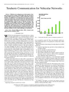
device and central controller with different protocols and standards in the micro-grid system. II. MICRO-GRID COMMUNICAITON SYSTEM ELEMENTS The structure of the AC&DC hybrid power system is shown in Figure 1. In the DC part, we have two 6 KW PV modules, which is connected to the DC bus via the DC/DC converter. We set one DC power supply is 15 KW, the other DC power supply is 100KW in the DC side to simulate the other type DC source. We also set one lead carbon battery and one lithium ion battery to storage the power from PV module and DC power supply, which are also connected to DC bus via DC/DC converter. In the DC side, we plug in two DC e-load, which power is 15.6KW to simulate the DC load. The AC side is consisted by one 60 KVA grid simulator, one 150KVA AC source, one 6 KVA AC source, two 50 KW AC load. The grid simulator is used to simulate situation that the AC&DC system is connected to the power grid. The two AC sources are used to simulate the wind turbines and other AC source. The AC load is used to simulate the load of power grid. Then the AC bus and DC bus is connected together by two bi-direction DC/AC convertors(BIC), which can realize the power flow between DC and AC side to make the system power be more effectively. So we establish the AC&DC hybrid system contains AC and DC part in our lab like Figure 1, which can simulate the real micro AC&DC hybrid power system situation.
Fig. 1 Structure of the AC&DC hybrid power system
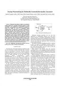
There are some devices like AC/DC power meters, AC source/load, DC source/load, battery, converters/inverters etc in the hybrid system, which status information must be known by the remote control center, based on this information, we can know the real time situation of our system, and then remote monitor and control the system, which could lead to make the system work more effectively and reliability. So establishing a effectively and reliability two-way communication system for the hybrid system is very necessary. Based on the communication requirement of the hybrid system shown in Fig.1, the communication system diagram is shown in Figure 2. The devices shown in Figure 2 are all needed to send the status information to the remote control centre. Especially all the AC source/load, DC source/load, converters, inverters, battery management system are designed to have the
function of two-way communication with the remote control centre to realize the remote control function of the system. But, the devices species diversity leads to inconsistent communication protocols exist in one hybrid system. How to integrate all the different protocols to realize the effectively and reliability two way communication is the most important.
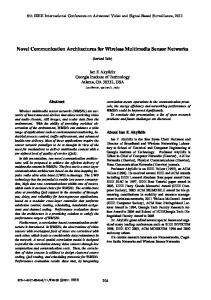
Fig. 2 Diagram of communication part III. ARCHITECTURE OF COMMUNICATION SYSTEM A. Physical Architecture In order to solve the problem of species communication protocols exist in one hybrid system, firstly we must know that what protocol we have based on every terminal device, then design the suitable solution for each communication protocols. Based on the devices characteristic we found that there are 4 type communication protocols in the hybrid system. They are RS485 for AC/DC meter and DC e-load, RS232 for AC source/load, LAN for grid simulator, battery management system and DC power supply, CAN 2.0 for convertor/inverter. Except to increase the communication speed, the other effective mean to reduce the communication delay between the terminal device and the control centre is reduce the relay numbers between the terminal device and the control centre. So based on the highest communication speed in currently protocols, we try our best to find the solution to use as less relay nodes as possible to reduce the communication delay. So we established the communication system shown in Figure3. We select one 24 ports switch box for collecting all the devices data, transmit them to the control centre and forward the control commend from the control centre to the terminal devices. The switch box supports IEC61850 standard, and the communication speed is 100Mbits/s. The switch box supports the TCP/IP, but most of the terminal devices do not support the TCP/IP protocol, so we need to find some ways to solve the problem. The Nport which can bi-direction transform between RS485/232 and TCP/IP is selected to bi-direction transform the RS485/232 to TCP/IP, so the AC/DC power meters with RS485 port and the AC source/load, DC source/load can communicate with the switch box after the protocol transformation via the Nport. The converter and inverter support CAN2.0 protocol, and the real time
requirement is key important, so the beaglebone board (BBB) is selected which can provide high speed protocol transform and local control function. Thus can improve the communication speed and reliability of the converter and inverter, then improve the real time requirements of the converter and inverter. For the device with LAN communication port like power grid simulator and DC power supply, which can communication with switch box directly by setting the unified IP address with switch box. For the Nport, it is also needed to set the unified IP address with switch box, BBB and control centre.
Fig.3 Structure of the communication system
on/off, rectifier/inverter, plug in the power grid or not etc. Then, collecting and analyzing the device date to monitoring the status of the system. The data collection cycle is set up based on the terminal device requirement. For example, the cycle of converter is much shorter than the power meter cause the real time requirement of the converter is much more than the power meter. The control centre compare the device data with the set value of the device which is storage in the server time to time. If there is no data exceed the threshold value, the control centre continue to collect the data all the time. Once the date value from the device exceed the set threshold value, for example the DC bus voltage is higher than the set threshold, the power meter send the real-time data and alarm data to the control centre. The control centre send control commend to the relative terminal device to reduce the voltage of the DC bus. At the same time, the control centre collect the device data all the time and compare the date value with the set up threshold value. If the device value still exceed the set threshold value after the control centre send the control commend to relative device, then the control centre send control commend to relative devices again, till there is no collection data value exceed the set up threshold value, the main program comes to the end. Based on the design program, the communication system of the hybrid system can be work on effectively and reliability.
The higher layer of the system is consist of the BBB, control centre and PC server, which are connected with switch box directly. For the 3 higher layer BBB, one is used to handle the data from terminal device with RS485 communication port like power meter, the second BBB is used to handle the data from terminal device with RS232, and the third BBB is used to handle the data from terminal device with LAN port. The aim we design like this is to let the device data can be handle effectively and reduce the delay of control commend from control centre to terminal devices. At the same time, all the terminal data are send to the control centre and PC server. The data of terminal device are displayed at the control centre for monitoring and storage in the PC server. After the hardware is completed, the graphical user interface (GUI) is needed to display the situation data more intuitive and realize the remote control. The GUI is based on the website, so we can access our GUI system at any place with internet access, which let the using of GUI to realize remote monitoring and control be more flexible. With the software and hardware, the 3-layer communication system for the hybrid AC&DC system is completed. B. Function Implementing Based on the hardware of the communication system, the developing of the software is needed to realize the remote monitoring and control. The communication system data collection, remote monitoring and control main flow chart is shown in Figure 4. Firstly, the system initialization include the setting up of terminal device initial value, power-on status detecting, the setting up of terminal device function like turn
Fig. 4 Flow chart of monitoring and control
IV. INTERGATION OF COMMUNICATION SYSTEM For the users of the hybrid system, the feature of GUI is directly relative with the system easy use and intuitive or not. So the designing of feature-rich, easy use and beautiful interface for the communication system is very important. Based on the structure of the hybrid system shown in Figure 1, we design the GUI shown in Figure 5. It contains all the device of the hybrid system like Figure 1 shows. Then the GUI can read the newest data value from the PC server directly and display all the device status information time to time to monitoring the real time system status. The refresh rate can be set from milliseconds to several seconds according to the requirement. We also can control the device via the GUI remotely. For example, we can set the DC/DC converter value of power, current and voltage, turn on/off the AC/DC power supply, connect/disconnect the PV array from the DC bus, connect/disconnect the AC/DC load from the hybrid system. Because of the GUI read the data from the PC server directly, the delay of the GUI display is very short, which can be ignored. Thus also reduce the system delay, which make the communication system more effectively.
V. CONCLUSION In this paper, a relative optimization 3-layer communication structure architecture for AC&DC hybrid micro-grid is presented. Reducing the system delay from the aspect of communication architecture. Based on the hybrid micro-grid system in our lab, the hardware and software of the communication system are designed and implemented. The system can solve the problem that there are specious communication protocols in one micro-grid system. It uses as little as possible relay node(physical communication layer), which can meet the requirement of the system. We can use this system to do some test in our lab, and this system can give some reference to other practical projects in the communication system design. Now it still have some problem need to be improved for this communication system in the future: (1)The 3-layer architecture is designed basic, it is just designed for meet the requirement of our system. Developing and optimizing a communication system for hybrid mico-grid system with general applicability is our next goal. (2)In this system, we use some other auxiliary equipment to realize protocol conversion, for example, we use Nport to convert between RS485/232 and TCP/IP. In practical hybrid micro-grid, it is not easy and suitable to use these device, which may lead to the low reliability of the hybrid micro-grid. So how to unify the communication protocol in the system, and reduce the auxiliary equipment number is necessary. (3)It is not easy to measure the communication delay of the system. The delay is the key indicator of the communication system performance. Finding some way to get the delay, which can give us much reference to optimize the architecture of communication system. REFERENCES
Fig. 5 Structure of GUI
According to the test result, the typical communication delay from terminal device to control centre is about milliseconds. For most part of the hybrid system, thus can meet the requirement completely. For the converter and inverter, the delay seem like longer. So we use the BBB to local control, storage and analyze the data from the converter and inverter to make the control of them is more effectively, which can improve the reliability of the hybrid system. The hardware and software are the basement of the communication system, the GUI is the core part of the communication system. Rational hardware and software design can improve the system performance.
[1]
[2]
[3]
[4]
[5]
[6]
Rana M M, Li L. Microgrid state estimation and control for smart grid and Internet of Things communication network[J]. Electronics Letters, 2015, 51(2): 149-151. Wang B, Sechilariu M, Locment F. Intelligent DC microgrid with smart grid communications: Control strategy consideration and design[J]. IEEE Transactions on Smart Grid, 2012, 3(4): 2148-2156. Giusti A, Salani M, Di Caro G A, et al. Restricted neighborhood communication improves decentralized demand-side load management[J]. IEEE Transactions on Smart Grid, 2014, 5(1): 92-101. Arefifar S A, Mohamed Y A R I, El-Fouly T. Optimized multiple microgrid-based clustering of active distribution systems considering communication and control requirements[J]. IEEE Transactions on Industrial Electronics, 2015, 62(2): 711-723. Sortomme E, Venkata S S, Mitra J. Microgrid protection using communication-assisted digital relays[J]. IEEE transactions on Power delivery, 2010, 25(4): 2789-2796. Liu S, Wang X, Liu P X. Impact of communication delays on secondary frequency control in an islanded microgrid[J]. IEEE Transactions on Industrial Electronics, 2015, 62(4): 2021-2031.