Vdd decay techniques, loses state, it has very low leakage, smaller area, and ... transistor memory technologies for decay applications. Be- ..... On Advanced Re-.
1
Implementing Decay Techniques using Quasi-Static Memory Cells �
�
Philo Juang , Phil Diodato , Stefanos Kaxiras , Kevin Skadron� , Zhigang Hu , Margaret Martonosi , Douglas W. Clark � Princeton Univ. Agere Systems � Univ. of Virginia Princeton, NJ Allentown, PA Charlottesville, VA Abstract— This paper proposes the use of four-transistor (4T) cache and branch predictor array cell designs to address increasing worries regarding leakage power dissipation. While 4T designs lose state when infrequently accessed, they have very low leakage, smaller area, and no capacitive loads to switch. This short paper gives an overview of 4T implementation issues and a preliminary evaluation of leakage-energy savings that shows improvements of 60-80%.
I. I NTRODUCTION Although dynamic (switching) power is the dominant source of power dissipation today, static (leakage) power is increasing exponentially and is projected to become severe over the next several technology generations, with some estimates as high as 50% or more of total power within five years. The largest source of leakage power is in large array structures, of which caches and branch predictors are among the largest. A variety of recent work has proposed techniques to identify unused portions of the cache and place them in a low-leakage standby mode, including both state-losing techniques like gated-Vdd/cachedecay [12], [19] and state-preserving techniques like dualVdd “drowsy-cache” [7] and leakage-biased bitlines [9]. The risk of state-losing techniques is that premature deactivation may lose useful data, incurring a later induced cache miss. State-preserving techniques avoid this problem but have higher standby leakage currents. All these techniques have the potential problem of large capacitive loads that must be switched when moving between active and standby modes. All cache leakage-control techniques so far have been based on traditional six-transistor (6T) SRAM cells. In this paper, we propose an alternative leakage-control technique based on four-transistor (4T) cells which are not static. 4T cells have been proposed before for several uses, including that of high-density on-chip caches [3], [13], but this paper focuses on the advantages of a 4T design for controlling leakage. Although a 4T implementation, like 6T gatedVdd decay techniques, loses state, it has very low leakage, smaller area, and no capacitive loads to switch. In addition, as process technology advances, leakage is likely to rise faster for 6T cells than for 4T cells which use longerchannel transistors. In [11] we introduced a 4T design for branch predictors. In this paper, we show how to implement leakage savings using 4T cells for caches, give preliminary evaluation for both caches and branch predictors to suggest that 4T designs are an attractive way to manage leakage in array structures, discuss some implementation issues, and conclude with future work ideas.
II. E XPERIMENTAL S ETUP Simulations in this paper are based on the SimpleScalar 3.0 and Wattch 1.02 toolkits [1], [2]. Our model processor has microarchitectural parameters that resemble in most respects the Intel PIII processor [4]. The main processor and memory hierarchy parameters are shown in Table I. For state-losing techniques, our simulations capture the extra delay and dynamic energy dissipation of induced misses. Results are evaluated using benchmarks from the SPEC CPU2000 suite [16]. Benchmarks are compiled and statically linked for the Alpha instruction set using the Compaq Alpha compiler with SPEC peak settings and include all linked libraries. For each program, we skip the first billion instructions to avoid unrepresentative behavior at the beginning of the program’s execution. We then simulate 200M (committed) instructions using the reference input set. Instruction Window Issue width Functional Units
L1 D-cache Size L1 I-cache Size L2 Memory TLB Size
Processor Core 40-RUU, 16-LSQ 4 instructions per cycle 4 IntALU,1 IntMult/Div, 4 FPALU,1 FPMult/Div, 2 MemPorts Memory Hierarchy 32KB, 1-way, 32B blocks, 3-cycle latency 16KB, 4-way, 32B blocks, 3-cycle latency Unified, 256KB, 8-way LRU, 32B blocks,8-cycle latency, WB 100 cycles 128-entry, 30-cycle miss penalty
TABLE I C ONFIGURATION OF SIMULATED PROCESSOR .
To derive concrete values for leakage currents and any dynamic-power overheads, we conducted circuit-level simulations with 6T and 4T library cells from Agere’s COM2 (160nm, 1.5V), COM3 (120nm, 1.0V), and COM4 (100nm, 1.0V) processes. Because leakage current is exponentially dependent on operating temperature, we conduct our studies at ����� C. Circuit simulations were conducted using Celerity tools at a 25 picosecond resolution. In this paper, we only evaluate 4T techniques in comparison to a baseline 6T implementation without leakage control because of the difficulties in accurately estimating the cost for switching a row in a 6T RAM array between active and standby states for various leakage-control techniques as well as the areas or access times of the different implementations. These are necessary for comparison to recently-proposed leakage-control techniques like drowsy cache [7], which uses two power supplies. As 4T cells decay of their own accord, at the circuit-level these modeling problems do not arise. In [11], we compared the leakage savings between 6T/gated-Vdd and 4T implementations of
2
a branch predictor (i.e., both state-losing techniques) and found that not only does the 4T design avoid the need to switch heavily-loaded gating transistors, but also gives better leakage savings than the 6T design. Comparing 4T techniques to state-preserving techniques is an area for future work. III. D ECAY
WITH
4T RAM C ELLS
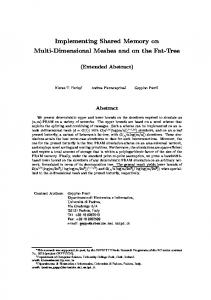
Quasi-static cells have been previously proposed and used for a number of reasons [8], [14]. First, they offer a method for easily implementing dynamic RAM (DRAM) in a logic fabrication process [15], [17], especially in embedded systems where the technology is known as EDRAM. Second, since the charge they store naturally decays over time, they are a natural candidate for implementing “cache decay” [12] or “branch predictor decay” [11]. This section examines a way of avoiding the disadvantages of the gated-Vdd approach by using quasi-static fourtransistor memory technologies for decay applications. Because of their use as embedded DRAM in some designs, 4T cells are already present in many design libraries, We use the cells as they appear in the Agere Systems design library. A. The Quasi-Static 4T Cell Basic 4T DRAM cells are well established and described in introductory VLSI textbooks [18]. 4T cells are similar to ordinary 6T cells but lack two transistors connected to Vdd that replenish the charge that is lost via leakage (Figure 1). Using exactly the same transistors as an optimized 6T design, the 4T cell requires only 59% of the cell area [5]. Performance-wise the 4T cell is virtually the same; while our data demonstrates a slight speed disadvantage, the difference is so small that coupled with the smaller amount of parasitic interconnect, the difference essentially disappears. More importantly, 4T DRAM cells naturally decay over time (without the need to switch them off); once they lose their charge they leak very little since there is no connection to Vdd. However, some secondary leakage via the access transistors still remains due to bit-line precharging which we do take into account in our transistor-level simulations. B
Vdd
B
B
B
the order of 100 mV (for 1.5V designs). Below this threshold we have a decayed state, where reading a 4T DRAM cell may produce a random value—not necessarily a zero. Over a long time the cell reaches a steady state where both the high node and the low node of the cell “float” at about 30 mV (for 1.5V designs). 4T cells possess two characteristics fitting for decay: they are refreshed upon access and decay over time if not accessed. In the rest of this section we discuss extensively the 4T decay design, including decay or hold times, dynamic energy, metastability, and other considerations. B. Retention Times In 4T Cells The critical parameter for a 4T design is retention time. Retention time is defined as the time from last access to the time when the internal differential voltage of the cell drops below the detection threshold. Retention time depends on the leakage currents present in the 4T cell which in turn depend on process technology variations and temperature. To study retention times in 4T cells we use Agere’s COM2 0.16u CMOS process for which we have accurate transistor models. We use COM2 because it is the most modern of the four COM processes that are available to validate our models against real measurements. Though this particular technology does not suffer excessively from leakage, our analysis scales to future generations. We target an operating temperature of � �� C but also discuss mechanisms to adjust in high temperatures ( � ��� C). Finally, as shown in Table II, selecting 3.3V I/O transistors—readily available in COM2 technology—to replace the 1.5V transistors while maintaining 1.5V signaling in the 4T cells significantly extends retention times at the expense of increased cell area. Even in this case the 4T cell area is still less than that of the 6T cell. (There is roughly an 18% difference.) Building 4T cells out of 3.3V-sized transistors while operating them at 1.5V is feasible because of the nature of the 4T cell which acts as a placeholder for charge. The same cannot be done for an active 6T circuit (two cross-coupled inverters) which requires its transistors to be fully biased to work correctly. Temperature Hold Time(ns)
25C 18K
standard 4T 85C 125C 1.7K 0.56K
25C 1M
slow-decay 4T 85C 125C 57.2K 9.4K
TABLE II
W
W
W
W
Fig. 1. The 6T SRAM cell (left) and the 4T quasi-static RAM cell (right).
4T cells are automatically refreshed from the precharged bit lines whenever they are accessed. When a 4T cell is accessed, its internal high node is restored to high potential, refreshing the logical value stored in it; there is no need for a read-write cycle as in 1T DRAM. As the cell decays and leaks charge, the voltage difference of its internal nodes drops to the point where the sense amps cannot distinguish its logical value. This occurs when the node voltage differential drops below a threshold; as a conservative setting, on
H OLD TIMES IN NS FOR STANDARD AND SLOW- DECAY VERSIONS OF 4T CELLS . F OR A 1 GH Z (1 NS CYCLE TIME ) PROCESSOR , ONE CAN CONSIDER THESE RETENTION TIMES AS CYCLE COUNTS .
Based on these assumptions, we determine retention times for our technology through detailed transistor-level simulations. We simulate an access to a cell, followed by a long period in which the cell is left unread. During this time, leakage causes the cell’s internal nodes to lose charge. As mentioned above, we use 100 mV as value criteria for the minimum voltage we would expect the sense amps to distinguish. Retention times in nanoseconds for the COM2 process appear in Table II. In future generations, we expect that cycle times will continue to drop, while leakage will increase. Therefore, to first order, retention times counted in cycles will go down slowly if at all. The success of a 4T design depends on matching retention times to access (i.e., “refresh”) intervals. A further way
3
C. Cache Decay Considerations As mentioned, reading a decayed cache line will produce a value, albeit random. This necessitates the use of decay counters. In 4T designs, the decay counters are used not to “switch off” cache lines (since this is unnecessary) but rather to indicate via the stable (6T SRAM) valid bits when the values of the 4T cells become unreliable because of their natural decay. The decay counters are set to prevent reading a cache line after the retention time has elapsed, to prevent the possibility of error or metastability from reading decayed data. We use the same hierarchical counter structure discussed in [12], with a global counter and cascaded local counters per cache line. The global counter avoids the need for large per-line counters; the local counters are incremented every time the global counter rolls over, and the line is regarded as unsafe to use after the local counter saturates. The global counter here plays an important role: it is via the global counter that we adapt to operating temperature. A temperature-sensing circuit can adjust the relative magnitude of the global counter to account for progressively smaller hold times with higher temperatures. In the case where the hold time becomes unacceptably low, refresh must be used to preserve performance. For decay counters, more bits afford finer granularity for decay, but also consume more leakage energy and require more area. When the hold time is large (tens of thousands of machine cycles for GHz clocks) the local cache-line decay counters can be very coarse grained (i.e., with very low resolution). In this case single-bit local cache-line decay counters can be used. The global counter ticks at a period half the hold time. Since the last access to a cache line in relation to the next global tick pulse is unknown, decay intervals range from half hold time to a full hold time. On average, for a random access the decay interval is 3/4 of the hold time. Another important issue here concerns writeback of dirty data. A simple solution is to require the writeback of any dirty data (indicated by the dirty bit) at the point when its local counter reaches the decayed state. The action of writing back the data actually refreshes and cleans the data. Thus, in this design written data have larger decay intervals than unwritten data.
random prediction as a result, it only induces a performance effect and does not affect correctness. Yet if we directly read possibly decayed values, this introduces a possible metastability concern. Many techniques exist for preventing this; one technique we proposed in [11] is to add a dummy column in the 4T RAM array with a voltage comparator (set to 100 mV or some more conservative value) that will gate off the sense amplifiers and instead force the branch-predictor output to a fixed value, e.g. not-taken. This is the model we adopt for our evaluation in the next section. IV. R ESULTS A. Results for 4T-based Caches To demonstrate with a more concrete example the feasibility of the 4T design, we simulate the L1 instruction and data caches. For our experiments, we simulate with a 3.3V sized 4T cell, giving us a 57,200 cycle decay interval at 1 GHz and � ��� C. For the decay counters, we use a 1 bit counter. The L1 instruction cache is the easier of the two cases to build; as a read-only structure, we need not be concerned with writebacks. Thus, the only effect is a negligible increase in the miss rate. The average miss rate of the standard, non-decaying L1 I-cache is 0.522%; for the 4T version, it is 0.536%, and so decay causes applications to run less than 0.25% slower on average. For this performance hit, however, we gain massive savings in leakage energy; fully 80% of the L1 instruction cache, on average, would be decayed. In other words, we consume only 20% the leakage power of a normal cache, yet provide virtually the same performance. To further illustrate these points, we can examine the data cache. The data cache is somewhat more difficult to design than the instruction cache; if the data cache is writeback, there exists the possibility that dirty data will decay before it is written back to memory, so we write back the line before it decays. Furthermore, we must be able to ensure that the data will be transferred to a write buffer before it is lost. The decay counter thus serves two purposes—to signal when a block is decayed, as well as to initiate the writeback process when the dirty bit is on.
� � � ! � " ! # $ % � % & ')( * + *�, - � .�$ % � % & '/( * + *�, - � 1
0.9
0.8
normalized leakage energy
to affect retention times is to add devices such as resistors or capacitors to the basic 4T cell [6]. Such devices can be used to slowly replenish the lost charge. If the rate of replenishment is less than the leakage, the cell will still decay albeit much more slowly, and retention time can be extended significantly. This could be especially useful in designing a 4T L2 cache, where access frequencies are lower.
0.7
0.6
0.5
0.4
0.3
0.2
0.1
0
D. Branch Predictor Design Considerations Because RAM arrays are typically close to square in their aspect ratio, with branch predictors, a row in the RAM array contains potentially unrelated predictor values. Yet, as shown in [10], there is enough temporal and spatial locality in a row of two-bit counters to make cache-decay techniques applied to rows be effective for branch predictors as well. The more important difference is that in contrast to cache data, branch-predictor data are not true machine state, meaning that we can potentially eliminate the decay counters. If we unknowingly read a decayed value and get a
Fig. 2. better.
�������
�������
�������
Normalized leakage energy of a 1 bit 4T decay cache; lower is
In the D-cache, as in the I-cache, miss rate increases only negligibly. The overall miss rate of a standard L1 D-cache is 8.2%, versus 8.3% for the 4T based D-cache. With less than a 0.1% increase in the miss rate, decay causes applications to run just under 0.02% slower overall. In return for a virtually negligible hit in performance, we decay approximately 63% of the D-cache; that is, we save 37% of the leakage energy for almost no cost in performance.
4
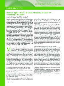
Figure 2 summarizes the energy savings and shows the normalized leakage energy of the decay caches. If the extra dynamic power cost of a slower-running application is higher than the total leakage energy savings, then decay is not worth it. Figure 2 shows the tradeoff cost for the three transistor technologies mentioned earlier; 1.0 is the breakeven point, and a result less than 1.0 represents a net savings. As we can see, decay posts a net savings in energy for all technologies shown. B. Results for 4T-based Branch Predictors We now examine the leakage and performance impact of branch predictor decay based on 4T structures. More detailed results can be found in [11]. We use slow-decay 4T cells in our design, both in the BTB and in the 16k-entry gshare direction predictor. The performance impact of predicting branches based on decayed predictor entries is negligible. Over all the benchmarks, performance was down less than 0.25%, while the overall prediction accuracy was down less than 0.5%. 6T
4T COM2
4T COM3
4T COM4
Acknowledgments This material is based upon work supported in part by the National Science Foundation under grants CCR-0082671, CCR-0086031, and CCR0105626. In addition, the authors gratefully acknowledge the support of the University of Virginia Fund for Excellence in Science and Technology, Intel, IBM, and Agere Systems.
1.8
1.6
1.4
Normalized Leakage Energy
This is an interesting point because 6T cells in this era have shown soft error problems due to large source-drain area. 1T cells (previously notorious for their soft error sensitivity) are not as bad as previously thought because their source-drain area is so small that the particle has a smaller target to hit. Furthermore, there is less of a charge imbalance because the cross-sectional area of the depletion region is so small. The 4T cell thus serves to be the practical middle ground between 6T and 1T. Our results so far suggest that 4T designs are an attractive way to save leakage energy in caches and predictors. 4T-based designs are also attractive because 4T cells are already a part of many standard-cell libraries; verification would include a single additional simulation that demonstrates the exponential decay of the internal nodes of the cell. This makes cache/predictor design possibly easier than for other leakage-control techniques, because 4T implementations are smaller than equivalent 6T implementations, and because they avoid the need to switch large capacitive loads as with sleep transistors to ground (gated-Vdd) or dual power supplies.
1.2
1
0.8
0.6
R EFERENCES
0.4
0.2
0
standard
slow decay
Fig. 3. Normalized leakage energy for branch predictors with standard (left) and slow-decay (right) 4T cells.
Figure 3 shows the normalized leakage energy with 4Tbased branch predictors. The leakage energy of a 6T branch predictor is defined as 1; a number lower than that indicates a processor equipped with a particular branch predictor consumed less energy, and vice versa. A processor with a 4T branch predictor consumes less energy under most processes. At COM2, the branch predictor decays too rapidly unless slow-decay transistors are used. V. C ONCLUSIONS This paper has proposed the use of four-transistor implementations of the cache and branch predictor as a way to save leakage energy in these structures. 4T cells save leakage because they lack the two lift-up transistors that maintain the cells’ charge. They therefore decay over time unless accessed within the horizon of their retention time. This means that they only leak as much energy as was deposited upon access. 4T cells thus provide a natural implementation of “decay” with very low leakage energy. A 4T implementation for a 100nm process can cut leakage in the data cache by 60%, in the instruction cache by 75%, and in the branch predictor by 80%, with negligible performance loss and some savings in area. Based on these early results, we argue that as leakage power becomes a major contributor to overall power dissipation, 4T cache and branch predictor designs merit further exploration. Furthermore, as process technology improves, other important issues arise, such as alpha particle immunity (and soft errors in general) for both 6T and 4T.
[1] D. Brooks, V. Tiwari, and M. Martonosi. Wattch: A Framework for Architecture-Level Power Analysis and Optimizations. In ISCA27, June 2000. [2] D. Burger, T. M. Austin, and S. Bennett. Evaluating Future Microprocessors: the SimpleScalar Tool Set. Tech. Report TR-1308, Univ. of Wisconsin-Madison Computer Sciences Dept., July 1996. [3] J. Cortadella and T. Jove. Dynamic RAM for On-chip Instruction Caches. Computer Architecture News, 16(4):45–50, Sept. 1988. [4] K. Diefendorff. Pentium III = Pentium II + SSE. Microprocessor Report, Mar. 8 1999. [5] P. Diodato et al. Merged DRAM-LOGIC in the Year 2001. Proc. of the IEEE International Workshop on Memory, Technology, Design, and Testing, Aug. 1998. [6] P. Diodato et al. Embedded DRAM: An Element and Circuit Evaluation. In IEEE Custom Integrated Circuits Conference, Jun 2001. [7] K. Flautner et al. Drowsy Caches: Simple Techniques for Reducing Leakage Power. In ISCA29, May 2002. [8] S. Hanamura et al. A 256K CMOS SRAM with Internal Refresh. In ISSCC, 1987. [9] S. Heo et al. Dynamic Fine-Grain Leakage Reduction using LeakageBiased Bitlines. In ISCA29, May 2002. [10] Z. Hu et al. Applying Decay Strategies to Branch Predictors for Leakage Energy Savings. In ICCD, Sep. 2002. [11] Z. Hu et al. Managing Leakage for Transient Data : Decay and QuasiStatic 4T Memory Cells. In ISLPED, Aug. 2002. [12] S. Kaxiras, Z. Hu, and M. Martonosi. Cache Decay: Exploiting Generational Behavior to Reduce Cache Leakage Power. In ISCA28, July 2001. [13] D. Lee and R. Katz. Using Cache Mechanism to Exploit Nonrefreshing DRAM’s for On-Chip Memories. IEEE Journal of SolidState Circuits, 26(4):657–661, Apr. 1991. [14] R. Lyons et al. CMOS Static Memory With a New Four-Transistor Memory Cell. Proc. of the 1987 Stanford Conf. On Advanced Research in VLSI, pages 111–132. [15] S. Schuster, L. Terman, and R. Franch. A 4-Device CMOS Static RAM Cell Using Sub-Threshold Conduction. In Symposium on VLSI Technology, Systems, and Applications, 1987. [16] The Standard Performance Evaluation Corporation. WWW Site. http://www.spec.org, Dec. 2000. [17] A. G. Varadi. Quasi-Static MOS Memory Array with Standby Operation. US Patent Number 4,120,047. [18] W. Wolf. Modern VLSI Design: Systems on Silicon. Prentice Hall, 1998. Prentice-Hall. [19] S.-H. Yang et al. An Integrated Circuit/Architecture Approach to Reducing Leakage in Deep-Submicron High-Performance I-Caches. In HPCA7, Jan. 2001.