Implementing the overall IIR filter in the form of BIQUAD sections ... shows how to
use the macros to implement an IIR filter. This code ...... specialized DSP chip.
M
AN852
Implementing FIR and IIR Digital Filters Using PIC18 Microcontrollers
Author: B. K. Anantha Ramu Microchip Technology Designs (India) Pvt. Ltd.
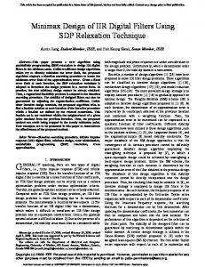
FIR FILTER IMPLEMENTATION Equation 1 shows the computation performed by an FIR filter.
EQUATION 1:
INTRODUCTION
Y[N] COMPUTATION
y[n] = x[n]*a0+x[n–1]*a1+x[n–2]*a2+....+ x[n-N+1]*aN–1 ®
The Microchip PICmicro PIC18 family of microcontrollers are popularly known for their logic and controlling functions. In addition, these microcontrollers have builtin hardware multipliers and multiple file pointers. These features, along with the built-in analog-to-digital converter (ADC), make PIC18 microcontrollers a competent choice for applications where logic and controlling functions are combined with signal processing applications. This application note demonstrates how the PIC18 family of microcontrollers can be used to implement digital FIR and IIR filters. Note:
This application note assumes the reader understands the basics of digital filters and their types. Refer to Appendix A should you require additional information.
The process of building a digital filter involves the following two distinct phases: • Design phase • Realization phase
Design Phase The design phase involves specifying filter characteristics (e.g., frequency response, phase response, etc.) and deriving the input output transfer function or filter coefficients from the specifications. Many software tools are available to generate filter coefficients from the specified filter characteristics.
Realization Phase The realization phase involves the selection of a structure to implement the transfer function. The structure may be a circuit if the filter is built by hardware, or may be a software program if implemented on microcontrollers.
2002 Microchip Technology Inc.
Where N is the number of taps and a0, a1, ... aN–1 are N filter coefficients. The N filter coefficients can be positive or negative depending on the characteristics of the filter. The computation performed by an FIR filter is implemented in a PIC18 microcontroller in two stages. First, the output value y1[n] is computed using the formula shown in Equation 2.
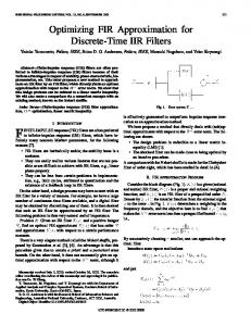
EQUATION 2:
Y1[N] COMPUTATION
y1[n] = x[n]*(a0 + 128) + x[n–1]*(a1 + 128) + x[n–2]*(a2 + 128)+...+x[n–N+1]*(aN-1 + 128) Second, X[n], as shown in Equation 3, is subtracted from y1[n] to obtain y[n].
EQUATION 3:
X[n] COMPUTATION
X[n] = x[n]*128 + x[n–1]*128 +...+ x[n–N+1]*128 X[n] represents the sum of all input samples from the latest to the previous N–1 samples, multiplied by 128. In calculating y1[n], we have added 128 to all filter coefficients. This is done to make the signed filter coefficients (supplied through the include file) unsigned to utilize the unsigned multiplier available in the PIC18 family of microcontrollers.
FIR Filter Code The code for the FIR filter is written in several individual macros. This enables the user to implement the FIR filter in a modular fashion. Flow Charts of the main routine and Interrupt Service Routine are shown in Figure E-1 and Figure E-2, respectively. The example code (expl_fir.asm) in Appendix D shows how to use the macros to implement an FIR filter. This code example includes several include files and macros. Table 1 lists the include files used and their descriptions.
DS00852A-page 1
AN852 TABLE 1:
FIR FILTER EXAMPLE CODE INCLUDE FILES
File Name
Description
Coef.inc
Defines the number of taps and filter coefficients.
Port.inc
Finds the TRIS ports corresponding to the ports OUT_PORT_HIGH and OUT_PORT_LOW selected by the user, and defines constants for Timer1, CCP2, and A/D Converter initialization.
fir_buf.inc
Defines buffer spaces used by FIR filter macros.
fir_mac.inc
Contains FIR filter macros.
Peri.inc
Contains macros to initialize TRIS ports, Timer1 registers, CCP2 registers, T3CON and A/D Converter registers.
int.inc
Contains a macro that enables interrupt priority, assigns high priority for A/D interrupt, enables high priority interrupt, and enables A/D interrupt.
Table 2 provides a list of the macros used and their descriptions.
TABLE 2:
FIR FILTER MACROS
Macro Name
Argument
Other Macros Invoked
Description
FIR_FILTER
None
RPT_MULACC, MULACC
Implements FIR filter. The number of taps and filter coefficients are defined in the coef.inc file.
MULACC
None
None
Multiplies the sample value pointed by FSR0 with the filter coefficient pointed by FSR2. The product available in PRODH:PRODL register is then added to the 24-bit value stored in the output_most, output_middle, and output_least variables.
RPT_MULACC
Rpt, loop
MULACC
Adds instructions to form a loop in which code for the macro MULACC is added ‘rpt’ times.
INIT_PERIPHERALS None
None
Sets up/initializes input port, output port, A/D Converter, CCP module and Timer1.
SET_INTR_FILTER
None
None
Sets up interrupt for real-time operation of the filter.
INIT_FILTER
None
None
Initializes the buffers used by the filter at the beginning of the program.
Depending upon the user setup, the parameters listed in Table 3 may need to be assigned.
TABLE 3:
FIR FILTER PARAMETERS
Value/Parameter Name
Description/Assignment
IN_PORT
Assign the port used to sample analog signal.
INPUT
The source register of I/P samples to the filter. When the A/D Converter is used, assign ADRESH.
OUT_PORT_HIGH
The port used to output the Most Significant Byte of the filter output. User must assign the port used for this purpose.
OUT_PORT_LOW
The port used to output the Least Significant Byte of the filter output. User must assign the port used for this purpose.
clock_freq
Assign the processor clock frequency used in Hz.
sample_freq
Assign the desired sample frequency in Hz.
num_of_mulacc
Depending upon the sampling frequency required and program memory available, assign a value >= 1 &