mote control (outside home), group control, etc. A system consisting of such networked home appliances is generally called a Home Network System (HNS, for ...
Implementing Integrated Services of Networked Home ∗ Appliances Using Service Oriented Architecture Masahide Nakamura, Hiroshi Igaki, Haruaki Tamada and Ken-ichi Matsumoto Graduate School of Information Science, Nara Institute of Science and Technology 8916-5, Takayama, Ikoma, Nara 630-0192, Japan {masa-n,
hiro-iga, harua-t, matumoto}@is.naist.jp
ABSTRACT
Keywords
This paper presents a method to implement integrated services of networked home electric appliances, which provide more convenient and comfortable living for home users. The conventional methods generally employ a home server to achieve the integrated services. The server controls all the networked appliances in a centralized manner. However, as the number of sophisticated appliances increases, the centralized server suffers from the concentration of load, as well as a decline in the reliability and interoperability. To cope with this problem, we adopt the service-oriented architecture (SOA) for the implementation of the integrated services. In the proposed framework, the appliances export own features as services, and autonomously execute the exported services one another. Thus, the appliances are loosely coupled via the exported services without any centralized home server, which enables more flexible, balanced and reliable integrated services. We first present a framework to design and implement the integrated services based on SOA, and then illustrate a prototype system developed with Web services. We also define three kinds of metrics (i.e., reliability, workload, and coupling), and conduct a comparative evaluation between the proposed and the previous systems.
Home Network System, Service Oriented Architecture, Implementation, Reliability
1.
INTRODUCTION
Recent advancement in processors and networks brings emerging technologies to network home electric appliances [3, 4, 9, 16]. Various home appliances, such as televisions, air-conditioners, DVD players, lights and refrigerators, are connected with a network at home. This provides many applications and services for home users, for instance, remote control (outside home), group control, etc. A system consisting of such networked home appliances is generally called a Home Network System (HNS, for short). Several HNS products have already come onto the market [8, 10, 12, 14, 18]. One of the major HNS applications is the integrated service of networked home appliances (we simply call integrated service in the following) [8, 9, 15]. The integrate service is to orchestrate different home appliances via network in order to provide more comfortable and convenient living for the users. Typical integrated service includes: Coming Home Service: When a user comes home, lights and an air-conditioner are turned on with appropriate illumination and temperature based on the current degree.
Categories and Subject Descriptors C.2.4 [Distributed Systems]: Distributed applications; C.0 [General]: System architectures; C.3 [Special-Purpose and Application-Based Systems]: Real-time and embedded systems
DVD Theater Service: When a user turns on a DVD player, lights become dark, 5.1ch speakers are selected and the volume is automatically adjusted.
General Terms
The conventional approach to implement the integrated service adopts the Server Centralized Architecture (SCA), where a sophisticated server (called home server) plays a role of a conductor. The home server controls all the networked appliances in a centralized manner, by sending control commands to the appliances in a certain order [8, 12, 15]. Since the server undertakes all the intelligent tasks of the orchestration, the structure of SCA is quite simple and intuitive. However, as networked appliances get more sophisticated and diversified, the conventional SCA would suffer from the following problems:
Design ∗This work is partly supported by Grand-in-Aid for COE (Center Of Excellence) and Encouragement of Young Scientists (No.15700058), from Research of the Ministry of Education, Science, Sports and Culture, Japan.
Permission to make digital or hard copies of all or part of this work for personal or classroom use is granted without fee provided that copies are not made or distributed for profit or commercial advantage and that copies bear this notice and the full citation on the first page. To copy otherwise, to republish, to post on servers or to redistribute to lists, requires prior specific permission and/or a fee. ICSOC’04, November 15–19, 2004, New York, New York, USA. Copyright 2004 ACM 1-58113-871-7/04/0011 ...$5.00.
Reliability, Load Concentration: Since all appliances are controlled by a centralized server, a crash of the server
269
makes all the integrated services unavailable. Also, the number of connected appliances directly reflects heavy workload of the server.
Integrated Service
Object Object
Object Object
Client
To cope with these problems, this paper proposes a new method to implement the integrated services based on the Service Oriented Architecture (SOA) [7]. The SOA is a system architecture to integrate autonomous distributed components. The components are loosely coupled with each other by strictly-typed interfaces and standardized communication protocols. In the proposed method, each appliance is divided into two layers: a service layer and a device layer. In the service layer, the appliance exports its control interfaces as a set of services. If a service is executed, then it sends a control command to the corresponding device with a proprietary protocol. Simultaneously, the service autonomously executes (uses) other services exported by other appliances. Thus, the appliances are loosely coupled at the service layer without any centralized server. This enables more flexible, robust and load-balanced integrated services. We first design the SOA-based integrated services with concrete service scenarios. Based on the design, we propose an implementation framework, and implement a prototype system with Web services [2, 24]. We also present a graphbased evaluation method of the integrated services. With this, we conduct an comparative evaluation of the proposed (SOA) and the existing (SCA) architectures, from the viewpoints of reliability, workload, and coupling.
2.1
Service A
Service B
Object
Exported Method
Interoperability: Since the home server needs to know the underlying protocols of all networked appliances, implementation of the server middle-ware becomes complex. Also, the server and the appliances are tightly coupled. Hence, it is hard to guarantee interoperability between them, especially when the versions of the protocols and the appliances are updated.
2.
Object
Exported Method
System Extension: Features of appliances that are not compatible with the server cannot be used in the integrated services. This limitation would become an obstacle to system extension for future appliances.
Tight Coupling Loose Coupling
Object Object
Figure 1: Service oriented architecture
the user and the service is achieved. Web Services [2, 24] are widely known as a major SOA framework. Figure 1 shows an example of SOA. A service user with the client application calls an exported method of Service A. Service A is implemented by tightly-coupled objects, which internally invoke another exported method of Service B. In this example, the service user uses an integrated service consisting of services A and B, which is depicted by a bold oval.
2.2
Assumptions on Networked Home Electric Appliances
For the development of the SOA-based integrated services, we assume that each networked home electric appliance satisfies the following conditions. Condition C1: Each appliance has device control interfaces that can be accessed by software (e.g., APIs). Condition C2: Each appliance has a storage to store application software (server and device control application), a processor to execute the application, and a network interface.
PRELIMINARIES These conditions do not impose unrealistic assumptions. We consider that these are standard features for next-generation home electric appliances. As for Condition C1, there already exist standards prescribing a detailed object template for each category of appliances [3, 4]. Condition C2 is justified by a fact that; the price and size of processors/memories are becoming reasonable to embed them in home appliances. Indeed, there already exist some commercial products involving Web applications, so that the users can configure and control the product from PCs through a Web interface (e.g.,[17, 21]).
Service Oriented Architecture and Integrated Services
The service oriented architecture (SOA) [7] is a system architecture to integrate different systems distributed over a network with a standard procedure. Each system exports own features to the network as a unit of service (a set of tasks, which is coarser than an object). The internal logic and implementation of the service are self-contained and encapsulated in the system. The system exposes only interfaces of the service in form of strictly-typed exported methods. A service user executes the remote exported method and gets desired results. This remote procedure call is performed by a standardized platform-independent framework. Also, once an exported method is deployed, its interface definition is not allowed to change. Therefore, the change in the internal service logic or service implementation platform do not influence the service user. Thus, the loose coupling between
2.3
Scenarios of Integrated Services
For more comprehensive discussion, we introduce example scenarios of the integrated services. In this example, we suppose an HNS consisting the following nine kinds of appliances (a DVD player, a TV, a speaker, a light, an illuminometer, a door (with a sensor), a telephone, an airconditioner and a thermometer). We also assume that one
270
Trigger Other Appliances
Generic Protocol
Service Layer
Exported Methods
Service Scenario Proprietary Protocol
Device Layer
User
1.1:Light.ON
Light
1.1.2:ON 1.1.3.2.1:setIllumination 1.1.3.2:Light.setIllumination
Device I/Fs
1.1.1:Illuminometer.ON
Trigger Other Appliances
1.1.3:Illuminometer.getIllumination
Illuminometer
1.1.1.1:ON 1.1.3.1:getIllumination
Service Layer
Light Device
Illumino meter Device
Device layer
Figure 2: Architecture of each home appliance
Figure 3: Design of service scenario SS1
appliance exists for each kind, and that the total nine appliances are installed in the same room.1 We prepare the following eight service scenarios (denoted by SSi (1 ≤ i ≤ 8)). These scenarios are determined based on the actual HNS products [8, 18].
loose-coupling among components with SOA is not a surprising approach. However, our contribution is to use SOA for the HNS application. For this, we present a concrete appliance structure and implementation framework. (B) Autonomous Orchestration without Centralized Server: Our application of SOA enables direct communications among appliances without any special servers. Therefore, the orchestration of the appliances, which has been undertaken by the conventional home server, can be distributed to the appliances. We present a method to implement the autonomous collaboration among appliances. Specifically, when an exported method of an appliance is executed, the appliance autonomously determines which exported method should be executed next, and triggers a remote procedure call to the other appliance.
SS1 : The brightness of the light is automatically adjusted with the illuminometer based on the current intensity of illumination. SS2 : If the user enters a room from the door, the light is turned on. SS3 : When the user turns on the DVD player, the light becomes dark. Then, the TV and the speaker start in the DVD mode. SS4 : When the user watches the TV, the speaker is turned on.
3.2
SS5 : If the telephone rings while the user is watching the TV, then the volume of the speaker becomes small.
To achieve the issues (A) and (B) in Section 3.1, we need to implement the following features in each appliances.
SS6 : The air-conditioning is optimized based on the thermometer.
(A) Exporting Self-Features: It encapsulates proprietary device interfaces, and exports the interfaces to a network using a standardized manner.
SS7 : If the user enters the room, the air-conditioner starts and adjusts the temperature to a comfortable degree.
(B) Controlling Other Appliances: It autonomously invokes interfaces of other appliances, according to a given service scenario.
SS8 : When the user goes out or goes to bed, all the appliances are shut down, and the door is securely locked up.
3. 3.1
Appliance Structure
To achieve them, we divide each appliance into two layers: a device layer and a service layer, as shown in Figure 2. The device layer refers to the hardware portion (including middle-ware) of the appliance. According to Condition C1, each appliance can be controlled by a software application via a set of device interfaces. Note that the control method is based on a proprietary procedure (or protocol) that the appliance conforms to (e.g., ECHONET for sensors and lights [4], IEEE1394 or UPnP for digital Audio/Visual appliances [23]). On the other hand, the service layer wraps the appliancespecific device interfaces and exports them to the network. The service layer is our original contribution for the SOAbased integrated services. We implement it as a software application on each appliance conforming Condition C2. Specifically, we wrap each of the device interfaces (e.g., for a light device, there should be interfaces for ON, OFF and illumination setting) in a method in the service layer. Then, we export the methods to the network in a generic
DESIGN OF INTEGRATED SERVICES Key Idea
Our key idea is to use SOA for achieving the following issues, which are difficult for the conventional server-centralized HNS. (A) Standard Communication and Loose Coupling among Appliances: We export features of each appliances as a set of exported methods, which makes the features accessible with the standard protocols in SOA. Thus, the appliances are loosely coupled. This significantly improves the interoperability and extendability of the HNS. Achieving 1 For multiple appliances in the same kind, we regard them as independent appliances. For example, if there are four lights in the room, we consider four instances; Light1, Light2, Light3 and Light4.
271
1.1 Light.ON 1.1.1,2.1.2.1,3.1.4.1 Illuminometer.ON 3.1.1 1.1.1.1,2.1.2.1,3.1.4.1.1 IlluminometerDevice.ON 8.1.1 1.1.3,2.1.2.3,3.1.4.3 Illuminometer.getIllumination 3.1.2 3.1.3 1.1.3.1,2.1.2.3.1,3.1.4.3.1IlluminometerDevice.getIllumination 8.1.2 1.1.3.2,2.1.2.3.2,3.1.4.3.2Light.setIllumination 3.1.2.1,4.1.1 1.1.2,2.1.2.2,3.1.4.2 LightDevice.ON 8.1.2.1, 1.1.3.2.1,2.1.2.3.2,3.1.4.3.2.1 LightDevice.setIllumination 3.1.3.1 3.1.3.2, 8.1.2.2 3.1.3.3,4.1.3 2.1,7.1 Door.statusCheck 3.1 4.1.2 3.1.3.4, 3.1.3.2.1,4.1.2.1 2.1.1,7.1.1 DoorDevice.statusCheck 4.1.4 8.1.2.2.1 3.1 DVD.ON 4.1 8.1 3.1.3.4.1,4.1.4.1,5.1.2.1 3.1.1 DVDDevice.ON 3.1.2 TV.ON 3.1.3.3.1,4.1.3.1 3.1.4 3.1.2.1,4.1.1 TVDevice.ON 1.1.2,2.1.2.2,3.1.4.2 3.1.3 TV.selectInput 1.1 8.2.1 3.1.3.1 TVDevice.selectInput 1.1.3.2.1,2.1.2.3.2.1,3.1.4.3.2.1 3.1.3.2,4.1.2 Speaker.ON 8.2 8.2.2 1.1.3.2 1.1.3, 3.1.3.2.1,4.1.2.1 SpeakerDevice.ON 1.1.1,2.1.2.1,3.1.4.1 2.1.2.3,3.1.4.3 2.1.2.3.2 2.1.2 3.1.3.3,4.1.3 Speaker.channelSelect 3.1.4.3.2 3.1.3.3.1,4.1.3.1 SpeakerDevice.channelSelect 1.1.1.1,2.1.2.1.1,3.1.4.1.1 3.1.3.4,4.1.4 Speaker.volumeControl 8.2.2.1 3.1.3.4.1,4.1.4.1,5.1.2.1 SpeakerDevice.volumeControl 1.1.3.1,2.1.2.3.1,3.1.4.3.1 2.1.2 Light.ON 2.1,7.1,8.3 5.1.2 3.1.4 Light.ON 4.1 TV.ON 8.3 2.1.1,7.1.1 5.1 5.1 Phone.statusCheck 8.3.1 5.1.1 PhoneDevice.statusCheck 8.3.2 7.1.2 5.1.2 Speaker.volumeControl 6.1 6.1 AC.ON 6.1.1,7.1.2.1 Thermometer.ON 5.1.1 6.1.1.1,7.1.2.1.1 ThermometerDevice.ON 6.1.2,7.1.2.2 Thermometer.getTemperature 6.1.2.1,7.1.2.2.1 ThermometerDevice.getTemperature 6.1.3,7.1.2.3 6.1.3,7.1.2.3 ACDevice.ON 8.3.2.1 6.1.4,7.1.2.4 ACDevice.setTemperature 6.1.4,7.1.2.4 6.1.1,7.1.2.1 7.1.2 AC.ON 6.1.2,7.1.2.2 8.3.3 8.2.2 Illuminometer.OFF 8.1 DVD.OFF 6.1.1.1,7.1.2.1.1 8.2.2.1 IlluminometerDevice.OFF 8.1.1 DVDDevice.OFF 8.3.3.1 8.3 Door.Lock 8.1.2 TV.OFF 8.3.1 DoorDevice.Lock 6.1.2.1,7.1.2.2.1 8.1.2.1 TVDevice.OFF 8.3.2 AC.OFF 8.1.2.2 Speaker.OFF 8.1.2.2.1SpeakerDevice.OFF 8.3.2.1 ACDevice.OFF 8.3.3 Thermometer.OFF 8.2 Light.OFF 8.3.3.1 ThermometerDevice.OFF 8.2.1 LightDevice.OFF
DVD TV
Speaker Light
User
Illuminometer Door
Phone AC
Thermometer
Service Layer
DVD Device TV Device
Speaker Device
Light Device Illumino meter Device Door Device Phone Device
AC Device
Thermo meter Device
Device Layer
Figure 4: Design of integrated services using SOA
3.3
manner, which does not depend on appliance-specific procedures or proprietary protocols. For the method exportation, we use a generic SOA framework such as Web services (with SOAP/XML and WSDL). Thus, all interfaces are opened to a network as a set of exported methods (i.e., a service), which achieves the above (A). Furthermore, in each exported method, we implement a mechanism by which the method autonomously triggers other exported methods provided by other appliances. Thus, the appliances are orchestrated at the service layer, and the above (B) is realized. The concrete implementation framework of the service layer will be discussed in the next section. For instance, we take a light and an illuminometer with Conditions C1 and C2, and try to design the SS1 (in Section 2.1) based on SOA. Figure 3 shows an example of the design. In the figure, an oval represents a service layer of an appliance. A device layer is depicted by an icon. A solid arrow from Service A to Service B with Label L shows Service A invokes (uses) method L exported by B. A dotted arrow represents a control command from a service layer to a device layer. Also, each method is indexed by a number which hierarchically specifies its execution order (the notation follows the one in UML collaboration diagram [5]). The service scenario starts when the user executes the exported method Light.ON. Then, Light service invokes other exported methods ON provided by Illuminometer. Then, each of Illuminometer and Light services respectively turns on the device. Next, Light service invokes Illuminometer.getIllumi nation, and Illuminometer service internally gets the current degree of illumination from the device. Then, Illumino meter sets the obtained illumination to Light by setIllumi nation method. Finally, based on the current degree, Light set the optimized illumination to the light device. Thus, we can make appliances autonomously orchestrate at the service layer, which implements the integrated services without the centralized home server.
Service Integration Graph
As shown in Figure 3, an integrated service can be characterized by HNS components (i.e., the user, services, devices, or a home server) and use/used relationships between the components. Hence, we introduce a graph-based notation for the integrated services. A labeled directed graph G is defined by G = (N, L, E), where N is a set of nodes, L is a set of labels, and E ⊆ N × L×N is a set of labeled directed edges. For a given integrated service scenario s, a labeled directed graph Gs = (N, L, E) is called a service integration graph, denoted by SIG(s), iff Gs satisfies the following conditions: • N is a set of all HNS components appearing in s, • L is a set of all methods appearing in s, and • An edge (p, m, q) exists in E iff p uses method m provided by q. Next, we extend the service integration graph to the set of scenarios. Let s1 , s2 , ..., sk be a given set of integrated service scenarios. Suppose that for i (1 ≤ i ≤ k), we have SIG(si ) = (Ni , Li , Ei ). Then, we define SIG({s1 , s2 , ..., sk }) = (∪i Ni , ∪i Li , ∪i Ei ) If s1 , s2 , ..., sn are all the scenarios in the HNS, then we call SIG ({s1 , s2 , ..., sn }) a full service integration graph, which is denoted by F SIG. Note that any SIG is a subgraph of F SIG by definition. For example, Figure 3 can be regarded as a SIG(SS1 ) by mapping each of ovals and icons to a node, an arrow to a labeled directed edge.
3.4
Designing Integrated Services with Service Oriented Architecture (SOA)
Here we design the eight service scenarios presented in Section 2.3 based on SOA. Figure 4 depicts an example of a full service integration graph F SIG(= SIG({SS1 , SS2 , ..., SS8 })) containing the scenarios from SS1 to SS8 . In the
272
3.1:ON 8.1:OFF
SS1
3.2,4.1:ON 8.2:OFF 3.3:SelectInput
SS2 SS1
SS4 SS5 SS6 SS7 SS8
Application
SS3
SS4 SS5
Gateway
SS3
SS2
User
3.4,4.2:ON 8.3:OFF 3.5,4.3,5.2:VolumeControl 3.6,4.4:ChannelSelect
SS6 SS7 SS8
Home Server
1.1,2.2,3.7:ON 8.4:OFF 1.4,2.5,3.10:setIllumination
1.2,2.3,3.8:ON 8.5:OFF, 1.3,2.4,3.9:getIllumination 2.1,7.1:StatusCheck 8.6:Lock 5.1:StatusCheck 6.1,7.2:ON 8.7:OFF 6.4,7.5:setTemperature
6.2,7.3:ON 8.8:OFF 6.3,7.4:getTemperature
DVD Device :Light
TV Device
HNS::User
Speaker Device
ON()
:Illuminometer
Light Device Illumino meter Device
:IlluminometerDevice
ON() ON()
ON()
getIllumination() getIllumination() setIllumination(illumination=$DMI getIllumination)
Door Device
$DMIgetIllumination
setIllumination(illumination)
Phone Device
AC Device
Figure 6: Sequence diagram for SS1
Thermo meter Device
executes the object SS3 to send appropriate control commands to the DVD player, the TV and the speaker. In the following, we use HNS-SCA to denote the conventional HNS where the centralized home server controls all of appliances.
Figure 5: Design of integrated services using SCA figure, the number appearing each label corresponds to the actual method described at the left side. Due to limited space, directed edges with the same method are represented by a single arrow. Each label starts with a scenario number i of SSi (1 ≤ i ≤ 8). The numbers following the scenario number hierarchically specify the execution order of the method in SSi . Take the scenario SS4 for instance. In Figure 4, we can see a possible design of SS4 by traversing arrows prefixed by “4.”. When the user first turns on TV (TV.ON), the TV service autonomously collaborate with the Speaker service, and sets the speaker volume and channel. Also, we can see that F SIG in Figure 4 contains SIG(SS1 ) in Figure 3 as a subgraph. SS3 can be designed by reusing scenarios SS1 and SS4 . The user first turns on DVD by DVD.ON. Then, the DVD service successively invokes Light.ON and TV.ON. Next, the Light and TV services respectively execute the same scenarios as SS1 and SS4 , which completes SS3 . In the following, we use HNS-SOA to denote the proposed HNS that extensively exploits SOA to achieve the autonomous and distributed collaboration of appliances.
3.5
:LightDevice
4. 4.1
IMPLEMENTATION Implementation Framework for Service Layer
This subsection presents an implementation framework for the proposed service layer. By definition, a service integration graph SIG(s) for a scenario s is equivalent to the UML collaboration diagram. So, it can be described as a sequence diagram [5]. For instance, SIG(SS1 ) in Figure 3 can be represented by a sequence diagram in Figure 6. In the figure, we can see that for the autonomous integration of the service layer, the following two types of method invocations must be implemented in each exported method. DMI (Device Method Invocation): DMI refers to processing of the service layer to send a device control command to the corresponding device layer. According to the proposed appliance structure (see Figure 2), there exists a single DMI for every exported method. DMI is constantly executed by the exported method regardless of the service scenario performed.
Designing Integrated Services with Server Centralized Architecture (SCA)
SMI (Service Method Invocation): SMI refers to processing of the service layer to invoke remote methods exported by other services. Several SMIs are performed before/after the DMI, depending on the current service scenario.
For the comparison purpose, we try to design the integrated services with SCA. In this approach, a home server sends control commands to the end appliances with the proprietary application and protocol [8, 12]. The home server directly communicates with the communication interface of each appliance. Hence, the service layer is not especially needed for each appliance. Instead, to orchestrate appliances with different network protocols, the home server must implement a gateway mechanism for the protocol conversion. Therefore, the implementation of the server tend to be more complicated. Figure 5 shows an example design. In this example, each of SS1 to SS8 is implemented as an application object which is tightly coupled with the gateway and other objects. Each object sends/receives control commands through the gateway to/from the appliances involved in the scenario. For example, when the user triggers SS3 , the server application
In Figure 6, each DMI is represented by a bold arrow, while each SMI appears as a thin arrow. For instance, the Light.ON method, which is exported by Light service, consists of a single DMI (LightDevice.ON), and two SMIs (Illuminometer.ON, Illuminometer.getIllumination) where the former is executed before the DMI, the latter is triggered after the DMI. Our implementation framework of the service layer is as follows. For each control interface d of an appliance, we create an exported method md . Then, we code md so that md invokes d internally, which implements the DMI. If d has a return value, we represent the return value by $DM Id .
273
Table 1: SMI definition file for SS1 (a) LightService (http://light.myhome.net/service.jws)
Context
SSID 1 ON() 1 setIllumination() 1
Context ON() getIllumination()
ServiceURI
Pre/Post methodName ON getIllumination null null
http://illuminometer.home.net/service.jws pre http://illuminometer.home.net/service.jws post
null
paramName null null null
paramType null null null
paramValue null null null
(b) IlluminometerService (http://illuminometer.myhome.net/service.jws) SSID ServiceURI Pre/Post methodName paramName paramType paramValue 1 null null null null null null
1 http://light.home.net/service.jws
post
On the other hand, SMI should not be hard-coded in md , since SMI depends on the service scenarios and can be added or modified by the user later on. Instead, for each appliance we prepare a definition file (called SMI definition file) which specifies how the SMIs are invoked in each service scenario. Each appliance dynamically looks up the definition file, and invokes appropriate SMIs at run time. For the addition or modification of the service scenarios, we just update the SMI definition file without modifying the implementation of the service layer. Table 1(a)(b) respectively show SMI definition files for Light and Illuminomter services shown in Figure 6. Each row corresponds a single SMI, consisting of the following entries: context (local exported method triggering the SMI), SSID (ID of the service scenario being executed), service URI ( URI of the remote service triggered), pre/post (before/after the DMI), methodName (name of remote exported method), paramName (names of parameters of the remote method), paramType (types of the parameters), paramValue (values of the parameters). When an (local) exported method is triggered in SS1 , each service looks up the table, then dynamically discovers and performs the appropriate SMI. In this example, the URIs of the two services are assumed to be http://light.myhome.net/service.jws and http://illuminome ter.myhome.net/service.jws, respectively. Based on the discussion above, the service layer for each appliance can be implemented in accordance with the following implementation template (as shown in Figure 7):
setIllumination illumination int
SMI Exported Method3{ preProcess(); deviceMethod(); Exported Method2{ postProcess(); preProcess(); } deviceMethod(); Exported Method1{ postProcess(); preProcess(); } deviceMethod(); postProcess(); }
SMI Definition
$DMIgetIllumination()
Exported Method3{ preProcess(); Exported Method2{ deviceMethod(); preProcess(); postProcess(); DMI Exported Method1{ deviceMethod(); } preProcess(); postProcess(); deviceMethod1(); } postProcess(); SMI } Definition
SMI
Exported Method3{ preProcess(); deviceMethod(); Exported Method2{ postProcess(); preProcess(); }
deviceMethod(); Exported Method1{ postProcess(); preProcess(); } }
deviceMethod(); postProcess();
SMI Definition
Figure 7: Implementation template for the service layer getIllumination() executes a post-SMI Light.setIllumina tion(). For this, a return value of the DMI ($DM IgetIllumination ) is passed to a parameter illumination. This achieves a service scenario SS1 , which set the illumination of light based on the current intensity obtained by the illuminometer.
4.2
• The service layer has exported methods each of which corresponds to a control interface in the device layer. • Each exported method implements deviceMethod() for the DMI. Moreover, preProcess() and postProcess() are implemented respectively before and after device Method(). preProcess() and postProcess() are routines that dynamically perform SMIs before and after the DMI according to the SMI definition file. These are commonly shared by all the exported methods in the service layer. For instance, consider Figure 6 and Table 1. When the user invokes Light.ON() method, it executes preProcess() and looks up pre-SMI from Table 1(a). As a result, Illuminometer. ON() is found and executed. Next, Light.ON() sends ON command to LightDevice as a DMI. After that, it executes postProcess() and looks up post-SMI from Table 1(b). As a result, Illuminometer.getIllumination() is invoked. Illuminometer service performs SMI with Table 1(b). Illuminometer.ON() has no SMI processing. Illuminometer.
274
Prototype System with Web Services
Based on the proposed implementation framework, we have implemented a prototype system. We exploited Web Services as a means of service deployment/exportation of the service layer. The prototype was developed under the following environment: Web server: Jakarta Tomcat 4.1.18 SOAP library: Apache-AXIS 1.1 Language: Java2 SDK SE 1.4.1 02 Also, we implemented each device layer as a virtual device. The class diagrams of the prototype system are shown in Figure 8. As seen in Figure 8(b), every service commonly inherits BaseService class, which 1. Interprets the SMI definition file and dynamically determines SMIs processed in preProcess() or postProc ess(), by using ServiceManager class. 2. Invokes remote WebService for the corresponding SMI, using DynamicCallerFactory class. Next, based on the service integration graph shown in Figure 4, we created an SMI definition file for each service, and uploaded the files to the prototype system. As a result, we
(a) Base classes
(b) Service classes
Figure 8: Class diagrams of the prototype system confirmed that all the integrated service scenarios SS1 to SS8 are executed correctly. An SMI definition file for a service s can be automatically generated by analyzing the given service integration graph, specifically, incident edges of the node s and their execution order. If the user wants to add or modify the service scenario, the user just uploads an updated definition file to each appliance. For this, there is no need to restart the Web server. Also, it is not necessary to re-configure or re-compile the application itself.
4.3
Roles in Proposed Framework
We here discuss the roles of the user and vendors of appliances in the proposed framework. First, we assume that the service applications (at the service layer) of each appliance should be developed by the vender, in accordance with the proposed implementation framework. For this, the vender does not need to concern how the applications are used by other appliances. Instead, the vender has to specify strictly-typed exported methods, and use a generic SOA framework such as Web services for the service deployment/exportation. With this, appliances are loosely coupled, which enables flexible extension and modification of new appliances. On the other hand, the service scenario development is supposed to be done by the user (Of course, the vender can pre-install the typical default scenarios). By our implementation framework, the service scenarios are completely separated from the implementation of the service layer. Hence, the user creates the service integration graph, derives SMI definition files, and then uploads the files to appliances. Thus, the user can easily develop integrated services consisting of any combinations of appliances. On creating the service integration graph, the user needs to know the detailed definitions of exported methods of appliances. This can be supported by integrated service creation environment, which exploits SOA’s service discovery techniques, such as WSDL and UDDI of Web services. We are currently developing the tool support for the creation environment. Figure 9 shows one of our tools - called service scenario scripting editor (S 3 editor). Using the editor, the user can edit own service scenarios. Note that the addition or modification of the service scenarios are not easy in the conventional HNS-SCA (see Figure 5), since the user needs to update the applications of the home server. It is generally hard for the generic users to
Figure 9: Service scenario scripting editor develop the control applications. Only what the users can do is to configure the setting of the ready-made applications, which significantly limits the flexibility and extendability of the service scenarios.
5.
EVALUATION
In this section, we quantitatively evaluate the proposed HNS-SOA from several architectural aspects. Specifically, for the service integration graph presented in Section 3.3, we define three kinds of metrics: reliability, workload and coupling. Then, we conduct a comparative study with the conventional HNS-SCA.
5.1
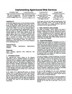
Reliability
Assuming that each HNS component may fail, we evaluate the system-wide reliability of HNS, from a viewpoint of the availability of the integrated services. For a given HNS with integrated service scenarios, we define n-reliability[6] as the probability that at least n service scenarios are operational in the HNS. The n-reliability varies depending on the HNS architecture as well as the reliability of each (single) component. To compute n-reliability, we apply the Sum of Disjoint Products (SDP) approach[6, 19, 22] to the service integration graph. The SDP is a method to derive the network reliability based on path-set and cutset of the graph theory. Intuitively,
275
when a graph G and reliability of each node (and edge) are given, the SDP method calculates reliability that at least one of specified set of subgraphs of G is operational, by taking the overlaps among the subgraphs into account. As discussed in Section 3.3, each service scenario s can be characterized by SIG(s), and a SIG is a subgraph of F SIG. Hence, n-reliability can be computed by SDP in such a way that some n SIGs are operational in F SIG. For instance, in Figure 4, 1-reliability is calculated by SDP as a probability at least one of SIG(SS1 ), ..., SIG(SS8 ) is operational. Similarly, 2-reliability is derived from SIG({SS1 , SS2 }), SIG({ SS1 , SS3 }) , ..., SIG ({SS7 , SS8}). Thus, taking all combinations from the given set of scenarios, we can compute n-reliability with the SDP method. To evaluate the reliability purely relevant to the architectural differences (see Figures 4 and 5), we do not consider any faults in the network or the device of each appliance. So, we assume that only the services (in HNS-SOA) and the home server (in HNS-SCA) may fail. Although it is generally difficult to estimate the reliability of each HNS component, we suppose that the reliability of each service in HNS-SOA is uniformly 0.999. As for HNS-SCA, assuming that the home server consists of eight tightly-coupled objects, we set its reliability to be 0.992(= 0.9998 ) (Actually, the reliability is expected to be lower than that, since we should consider the reliability of the gateway, strictly speaking). We have applied the SDP method to two service integration graphs in Figures 4 and 5. The result is shown in Figure 10. In the figure, the horizontal axis represents the number of service scenarios, while the vertical axis plots n-reliability. From the result, it can be seen that n-reliability for HNSSCA becomes equal to the reliability of the home server. This is because all service scenarios depend on the centralized server. In other words, if the home server fails, all the scenarios become unavailable. On the other hand, in HNSSOA, the eight scenarios are executed by the distributed services. Hence, even if some services crash, some scenarios can be partially operational. Thus, the SOA-based integrated services achieve higher fault tolerance than the SCA-based ones. For n = 7, 8, HNS-SCA achieves slightly more reliable than HNS-SOA. Since HNS-SOA contains more components than HNS-SCA, the probability that all the components in HNS-SOA are operational becomes smaller than that of HNS-SCA. Thus, there exists a trade-off relationship between the fault-tolerance and the probability that all systems are green.
5.2
n-Reliability
1
SOA SCA
0.998 0.996 0.994 0.992 0.99
n
1 1
2
3 4 5 6 7 # of scenarios(=n)
2
3
4
Architecture SOA 0.99999 0.99999 0.99999 0.99998 Type SCA 0.992 0.992 0.992 0.992
8
5
6
7
8
0.992
0.992
0.992
0.992
0.996 0.99302 0.99104 0.99104
Figure 10: n-reliability
defined as: W L(v) =
n X
fi × ci (v)
i=1
To obtain the usage frequency, we interviewed 12 users. We asked them the estimated usage frequency of SS1 to SS8 per week, and obtained the average number of usage of each scenario. Based on this, we calculate the workload of the service layer of each appliance (in HNS-SOA) and the home server (in HNS-SCA). Table 2 shows the result. The column shows the workload imposed to each service layer (or the home server) and the standard deviation. It can be seen that the workload is concentrated on the home server in HNS-SCA. In HNS-SOA, although Light and Illuminometer services suffer from relatively large workload, it is still smaller than that of the home server. Next, we consider the load-balancing schemes. In HNSSCA, the load is concentrated on the home server only, the server itself has to be load-balanced, for instance, by deploying a secondary server. As a result, the load-balancing is so global and inefficient that even unused services are loadbalanced. On the other hand, HNS-SOA is more efficient in the sense that only some services with heavy workload should be taken care of. For instance, in Table 2, if the user selects Light and Illuminometer services for the loadbalancing, only these services should be duplicated. Thus, more flexible and local load-balancing scheme can be applied to HNS-SOA.
Workload
We try to estimate a workload of each HNS component (i.e., the service layer in HNS-SOA and the home server in HNS-SCA) imposed by the integrated services. The workload varies depending on the appliances involved in an integrated services and the usage frequency of the scenarios. Suppose that F SIG = (N, L, E), SIG(si ) (1 ≤ i ≤ n) for scenarios si ’s, and usage frequency fi of scenario si are given. Now we define an appearance function ci : N → {0, 1} such that for v ∈ N , ci (v) = 1 if v is contained in SIG(si ), otherwise ci (v) = 0. The function ci checks if the node (component) is used in scenario si . Then, for each component v ∈ N , the workload of v, denoted by W L(v), is
Element DVD TV Speaker Light Illuminometer Door Phone AC Thermometer StandardDev
276
Table 2: Workload WL 10.7 26.1 29.8 57.4 57.4 18.7 3.7 18.1 18.1 17.925
Element Home Server StandardDev
WL 86.3 86.3
5.3
Coupling
(1) Since the appliances are loosely coupled at the service layer with SOA, the interoperability between appliances is improved. This facilitates addition and modification of the appliances.
The coupling is a metric to estimate how strongly an HNS component relies on (or is relied by) the other components. If a component v with extremely high coupling is broken or modified, many other components dependent on v are influenced, which prevents the integrated services from working correctly. For a given F SIG = (N, L, E), we define a coupling of node v ∈ N as the number of nodes connected to/from v. More specifically, for v ∈ N , let use(v) = |{v 0 |∃m; (v, m, v 0 ) ∈ E}| (i.e., # of components that v uses), and let used(v) = |{v 0 |∃m; (v 0 , m, v) ∈ E}| ((i.e., # of components that use v)). Then, the coupling of v is defined by coup(v) = use(v)+ used(v). For example, let us take TV service in Figure 4. Then, use(T V ) = |{Speaker, T V Device}| = 2, and used(T V ) = |{U ser, DV D}| = 2. Hence, coup(T V ) = 4. We compute the coupling for each component in Figures 4 and 5. Table 3 summarizes the result. It can be seen in that the coupling values of all services in HNS-SOA are wellbalanced. We can also see that the components in HNS-SCA are heavily concentrated on the home server. This implies that the crash of the server is fatal for all integrated services, which is as discussed in Section 5.1. Moreover, let us consider the density of each coupling (i.e., each edge in the service integration graph). In HNSSOA, services are loosely coupled. Hence, even if internal implementation or device control procedures of an appliance change, the other appliances do not have any effect, as long as the type definition of the exported method does not change. However, in HNS-SCA, the home server and each appliances are tightly coupled. Therefore, changes in either the server or the appliance significantly decline the interoperability. For example, when adding appliances that conform to a new device protocol to the existing HNS, we have to update the gateway implementation of the home server. This update significantly influences all the existing appliances, which is a serious cause to decline the interoperability among the new and existing appliances. Taking these into account, it is considered that the coupling is much stronger than the values in Table 3.
(2) Since the integrated services are realized by the autonomous collaboration among the appliances, the proposed framework does not need the centralized server. As a result, the integrated services become more faulttolerant and load-balanced. (3) Due to the proposed implementation template, the implementation of the service layer and the service scenarios are well separated. Therefore, it is easy for the user to add or modify the integrated service scenarios. We examine the relationship between SOA and each of these advantages. First, the above (1) is achieved by the nature of SOA, which is not limited to the HNS domain. The above (2) is due to the proposed service layer which extensively uses the merit of the loose coupling. We have implemented mechanisms of the exportation of the self-features as well as the control of other appliances (see Section 3.2) in the service layer. This allows us to decentralize the service orchestration task among appliances themselves. The implementation template in (3) makes full use of a characteristics of SOA by which we can use any feature of the appliance uniformly as an invocation of the exported method. With this, the service layer for every appliance has a common structure, where the control of other appliance and the exportation of the self-features are achieved as SMI and DMI, respectively. Also, the proposed implementation template looks up the content of SMI from the external definition file. This allows the separation of the service scenarios from the implementation of the service layer. Of course, the proposed framework is not perfectly superior to the conventional one. As the drawback in the fullydistributed control of the appliances with SOA, the following issues are currently anticipated: Cost of Appliances: Each appliance must be intelligent enough to satisfy Condition C2 (see Section 2.2), in order to realize the service layer. This makes the cost of appliances more expensive than the conventional ones.
Table 3: Coupling Element DVD TV Speaker Light Illuminometer Door Phone AC Thermometer HS
6. 6.1
coup
use
3 2 1 2 1 3 2 2 1 9
Communication Overhead: It is expected that the communication overhead required for the service orchestration cannot be ignored. Hence, when applying to the integrated services that require hard-realtime response, we need a careful consideration.
used 1 2 2 3 1 1 1 2 1 8
Global Management: Since the service control is fully distributed, it is hard to manage all the appliance at once. Hence, it requires more sophisticated mechanisms for detection of faulty appliances and application of global security policy, etc [20].
6.2
DISCUSSION
Related Work
BPEL4WS [1, 26] is known as a standard service orchestration framework. It is an XML-based language describing new services integrating the existing distributed service components. It might be possible to use BPEL4WS as an alternative of the service integration graph in the proposed
Advantage and Limitation
The advantages of the proposed framework are summarized as follows:
277
framework. Indeed, in [11], a service oriented method to orchestrate intelligent appliances using BPEL4WS is presented. However, the existing BPEL4WS platform needs the orchestration server (typically called BPEL engines), which follows a server centralized architecture. Therefore, the existing framework cannot be directly used for implementing the proposed HNS-SOA. A new language called WS-CDL (Web Services Choreography Description Language) [25] is currently being specified by W3C. The WS-CDL aims to strictly define observable interactions between services from a global point of view. It adopts π-calculus [13] as a mathematical foundation to deal with complex ordering and relationships among services. The application is focused mainly on the on-line transactions among enterprises. The WS-CDL might be used for modeling the integrated services in our HNS-SOA. However in practice, it is hard for the end users to define rigorous relationships among appliances. Also, the current HNS services do not require that much complex collaboration. Considering the convenience of users and the complexity of the current integrated services, we cannot see so many HNS applications to make full use of π-calculus and WS-CDL. Investigation of more sophisticated HNS services and application of WS-CDL is left to be our future work.
7.
[7] H. He, “What is Service-Oriented Architecture?” http://webservices.xml.com/pub/a/ws/2003 /09/30/soa.html [8] Hitachi Home & Life Solutions inc., “horaso network” - http://www.horaso.com/ [9] iReady - http://www.sharp.co.jp/corporate/news/ 031217-2.html [10] LG Electronics, “Home Network” http://www.lge.com/products/homenetwork/ homenetwork.jsp [11] S. W. Loke, “Service-Oriented Device Echology Workflows”, Proc. of 1st Int’l Conf. on Service-Oriented Computing (ICSOC2003), LNCS2910, pp.559-574, Dec. 2003. [12] Matsushita Electric Industrial Co., Ltd., Kurashi net, http://national.jp/appliance/product/kurashi-net/ [13] R. Milner, “Communicating and Mobile Systems: the Pi-Calculus”, Cambridge University Press, 1999. [14] Mitsubishi Rayon Co., Ltd., “Home network” http:// pofeska.com/tec/homenet1/homenet1.htm [15] Nippon Telegraph and Telephone Corporation, “Home Service Harmony” - http://www.ntt.co.jp/news/ news04/0403/040308.html [16] OSGi Alliance - http://www.osgi.org/ [17] PLANEX COMMUNICATIONS Inc., BRC-14V http://www.planex.co.jp/product/broadlanner/ brc14v.shtml [18] Samsung, “Home Network” - http://www.samsung. com/HomeNetwork/index.htm [19] S. Soh, and S. Rai, “CAREL: Computer aided reliability evaluator for distributed computing networks”, IEEE Trans. Parallel and Distributed Systems, July, pp.199-213, 1991. [20] F. Tartanoglu, V. Issarny, N. Levy, and A. Romanovsky, “Dependability in the Web Service Architecture”, Proc. of the ICSE Workshop on Architecting Dependable Systems, Orlando, USA, May 2002. [21] Toshiba Corporation, “net de navi” http://www.rd-style.com/ [22] T. Tsuchiya, T. Kajikawa, and T. Kikuno, “Parallelizing SDP (Sum of Disjoint Products) Algorithms for Fast Reliability Analysis”, IEICE Transactions on Information and Systems, Vol.E83-D, No.5, May , pp.1183-1186, 2000. [23] UPnP Forum - http://www.upnp.org/ [24] W3C Web Service Activity http://www.w3.org/2002/ws/ [25] W3C, “Web Services Choreography Description Language, Version 1.0”, http://www.w3.org/TR/ws-cdl-10/ . [26] S. Weerawarana, and F. Curbera, “Business process with BPEL4WS: Understanding BPEL4WS, Part1”, http://www-106.ibm.com/developerworks/ webservices/library/ws-bpelcol1/ . [27] M. Weiss, “Feature Interactions in Web Services”, Proc. of Seventh Int’l. Workshop on Feature Interactions in Telecommunication Networks and Distributed Systems (FIW’03), pp.149-156(2003).
CONCLUSION
In this paper, we have proposed a framework to design and implement the integrated services for home network appliances with the service oriented architecture (SOA). We have also conducted a comparative evaluation of the proposed HNS-SOA with the conventional HNS-SCA. In our future work, we evaluate the limitation of the proposed HNS-SOA from more practical viewpoint. For this, we are currently extending our prototype systems with more appliances and more service scenarios. Based on the evaluation, we plan to investigate the management framework and security schemes which well suit the SOA. Another interesting topic is the feature interaction problem[15, 27], which is known as functional conflicts among services. It is expected that many potential interactions exist in the HNS, since multiple users can activate multiple services simultaneously. Hence, detection and resolution of the feature interactions within the SOA framework are important issues.
8.
REFERENCES
[1] Business Process Execution Language for Web Services, Version 1.1: http://www-106.ibm.com/ developerworks/library/ws-bpel/ . [2] E. Cerami, “Web Services Essentials – First Edition” , O’Reilly & Associates Inc., United Stated of America, 2002. [3] Digital Living Network Alliance http://www.dlna.org [4] ECHONET Consortium http://www.echonet.gr.jp/ [5] M. Fowler, K. Scott, “Uml Distilled: A Brief Guide to the Standard Object Modeling Language”, Addison-Wesley, Boston, 1999. [6] S. Hariri, and C. S. Raghavendra, “SYREL:A Symbolic Reliability Algorithm Based on Path and Cutset Methods”, IEEE Transactions on Computers, October, pp.1224-1232, 1987.
278