Then, we show how to construct a compiler for the pro- posed language ... cess Control (MAC) layer, as well as coding and combining ex- tensions at the ...... reliefs the developer as only small parts need to be implemented by hand afterward.
In Proc. Intl. Conf. on Simulation Tools and Techniques for Communications, Networks and Systems (SIMUTools), Mar. 2008
Implementing MAC Protocols for Cooperative Relaying: A Compiler-Assisted Approach Hermann S. Lichte and Stefan Valentin Computer Networks Group University of Paderborn
{hermann.lichte|stefan.valentin}@upb.de ABSTRACT
r
Evaluating the performance of a cooperative relaying protocol requires an implementation for simulators and/or software-defined radios (SDRs) with an appropriate model for error detection, combining, and Medium Access Control (MAC) automaton. Such implementations are essential for meaningful evaluation of practical systems since any protocol introduces overhead that constrains the theoretical performance in non-obvious ways. Unfortunately, protocols for cooperative relaying often yield complex implementations which are tedious to implement and debug. Therefore, we identify basic operations that are inherent to all cooperative relaying protocols, and we propose a new language for their specification. Then, we show how to construct a compiler for the proposed language that generates most of the required implementation (model and MAC automaton) automatically. This approach prevents subtle mistakes during implementation of the protocol, and can significantly increase development time. In addition, this paper discusses code generation exemplarily for OMNeT++/Mobility Framework, but the approach is not restricted to a specific simulator or SDR.
Categories and Subject Descriptors C.2.1 [Network Architecture and Design]: Wireless communication; C.4 [Performance of Systems]: Performance attributes; I.6 [Simulation and Modeling]: Model Validation and Analysis
General Terms Performance, Experimentation, Measurement
1.
INTRODUCTION
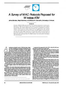
Cooperative relaying can substantially decrease the error rate of a wireless transmission by exploiting the broadcast nature of the wireless channel [14]. The basic idea is shown in Fig. 1, where a wireless transmission from source to destination is overheard by another user, called relay. If the wireless channel from relay to destination fades independently from that between source and destination, retransmission of the same data by the relay for combining at the destination yields a so-called user cooperation diver-
Retransmission d
s
Broadcast
Figure 1: The basic idea of cooperative relaying is to let another user, the relay, retransmit an overheard frame to provide a socalled user cooperation diversity gain at the destination.
sity gain, resulting in decreased error rates. Therefore, cooperative relaying is a key technology in state-of-the-art communication systems, but prototypes and implementations are still exceptional. How can this apparent contradiction be explained? If it is to be implemented, cooperative relaying gives rise to a myriad of protocol designs for controlling the relaying process. Such protocols are essentially needed to achieve the user cooperation diversity gains, and these protocols were classified and analyzed in [10]. This seminal work showed that under ideal conditions, full diversity gains can be reached by the Selection Decode-and-Forward (SD&F) approach. Subsequently, plenty of protocols were proposed that integrate cooperation into channel [6], network [2], space-time [7], or source coding [5], and their general performance bounds were derived using information-theoretic methods. Using simulations, the effect of realistic assumptions on the wireless channel has been extensively studied for various mobility [17], fading [19], and geometric [16] scenarios for ideal cooperation protocols. Although these theoretical analyses provide deep insight into general performance, protocols in particular systems always introduce overhead that constrains the general performance in non-obvious ways. Integrating user cooperation diversity, e.g., into IEEE 802.11 WLANs requires additional relaying protocols at the Medium Access Control (MAC) layer, as well as coding and combining extensions at the Physical (PHY) layer. The performance of such functions, their overhead, control latency, integration side-effects and, finally, the performance of the complete system has to be studied under realistic scenario assumptions. Here, simulation or prototype-based measurements are obligatory before manufacturers can decide which overall system design, comprising both layers, PHY and MAC, will eventually constitute their next-generation systems. Unfortunately, integrating cooperation into simulators or prototypes is an error-prone task whose complexity naturally leads to high development times. When a multitude of system designs must be evaluated first through simulations and prototypes, the process of implementing cooperation becomes the bottleneck that must be improved.
Best Paper Award
In Proc. Intl. Conf. on Simulation Tools and Techniques for Communications, Networks and Systems (SIMUTools), Mar. 2008
In this paper, we suggest a new design methodology that can automatize the process of implementing the most error-prone system components. Our methodology comprises three important aspects. Firstly, for simulations we provide a simple model based on Signal-to-Noise Ratio (SNR) to abstract the wireless channel and the effects of the PHY, namely modulation, coding, and combining. Secondly, for automatizing implementation, the conceptual design of cooperative relaying systems must be formalized. Therefore, we derive a new specification language based on observations of recurrent basic operations. These operations are domain-specific knowledge that implementations of cooperative relaying do apply. Thirdly, we illustrate how to build a code generator for cooperative relaying systems that uses our specification language as input. Code generators offer the highest payoff in terms of productivity [8]. Here, a code generator uses the domain-specific knowledge to automatically produce an implementation that consists of the PHY model (used in simulators) and MAC automaton (used in both simulators and prototypes) fitting the specification. In combination, these three aspects constitute a whole new framework that enables faster and more robust implementations of cooperative relaying systems than conventional approaches. The rest of the paper is organized as follows. Section 2 introduces simple channel and PHY models for cooperative relaying systems. For the specification of these systems, we introduce a new domainspecific language in Section 3. We then show in Section 4 how a correct model is formally generated from such a specification as well as the corresponding MAC automaton. This formalism is used to build a compiler for our domain-specific language. As a motivating example, we design a compiler for OMNeT++/Mobility Framework [18, 3] as the target, but we emphasize that other targets, e.g., a different simulator framework or even a software-defined radio (SDR), are possible. In Section 5 we apply our compilerassisted approach to generate the implementation of a simple cooperation protocol and compare the results achieved by the generated implementation with theoretical results. Finally, Section 6 concludes this paper.
2.
PHYSICAL COOPERATION MODELS
To simulate cooperation protocols under realistic channel and system assumptions, models reflecting the effects of the channel and the PHY layer on a cooperative transmission are required. These models and the required extensions for cooperative transmission are discussed in the following.
2.1
γs,r1 s
Cooperation protocols exploit temporal and spatial diversity in wireless fading channels. Hence, the gain of these protocols highly depends on the channel assumptions and modeling. Typical effects studied within the scope of wireless channels are path-loss, shadowing, large and small-scale fading. Small-scale fading, determining the variation of the wireless channel at small time scale, is caused by mobility in the propagation environment. We model small-scale fading using the typical “Jakeslike” method [1] with the “land mobile” Autocorrelation Function (ACF) (Table 2.1 in [15]). This model is parameterized by a maximum Doppler shift according to carrier frequency fc and velocity v of the fastest moving object in the propagation environment, e.g., a moving user. Furthermore, we assume a Non-Line Of Sight (NLOS) situation modeled by Rayleigh-distributed signal ampli-
d
γs,d
γs,rj γs,rJ
rj
γrj,d γrJ,d
Broadcast rJ
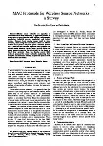
Figure 2: Cooperation scenario where source s may cooperate with J relays r1 , . . . , r j , . . . , rJ to reach destination d. The figure shows the instantaneous SNR values γ for the half-duplex channels used during phase 1 (solid line) and 2 (dashed line) of a cooperation cycle. All user terminals employ single antennas.
tudes and frequency-flat fading1 . Frequency-flat Rayleigh fading results in an exponentially distributed instantaneous SNR γi, j for the channel from user i to user j. The instantaneous SNR for different channels (i, j) is assumed to be i.i.d. which means, first, that all users are sufficiently separated in space and, second, that the channels are non-reciprocal, i.e., γi, j 6= γ j,i . The resulting autocorrelated, independent and identically-distributed (i.i.d.) Rayleigh fading model reflects a typical channel scenario found in office or urban environments with many small stationary and uniformly distributed scatterers and moving users. With moving users, naturally, the distance to the destination d may change over time. Therefore, path loss, modeling the attenuation of signals during propagation, becomes time selective – an effect also known as large-scale fading. Finally, shadowing abstracts many physical effects such as reflection, diffraction, scattering, and absorption. Typically, shadowing is modeled by i.i.d. log-normal distributed attenuation reflecting urban environments. Shadowing and fading are implemented in our simulator as a block model: γi, j stays constant during a single phase of the cooperation cycle. Therewith, each phase experiences a quasi-static channel while the ACF defines whether consecutive phases fade independently. Although these models are widely-used, naturally, they are not suitable for any situation. For example, a Nakagami-type amplitude distribution may be preferred for scenarios with LOS component, or a different ACF may be chosen to model an open-space scattering environment. In the channel model implementation, available at [12], all these components can be changed easily.
2.2
Channel model
γr1,d
r1 ...
Physical layer model
Fig. 2 extends the scenario in Fig. 1 to the general case where J relays may forward a packet of a single source s in each cycle. As illustrated, this cooperative transmission consists of at least two phases. In the first phase, the source transfers its packet to all J relays via a broadcast channel. Out of all J received packets, the relays may correctly decode L ≤ J packets. These packets are forwarded in the second phase via L orthogonal channels to d. Providing these orthogonal channels and separating the two phases causes cooperative transmission to only reach a rate of Rcoop = Rdir /(L + 1) as a fraction of the direct transmission rate Rdir . However, combining L > 1 packets at the destination introduces a diversity gain which decreases the Packet Error Rate (PER) exponentially in L. This gain can be fully achieved by using an optimal com1 In wide band systems, e.g., WLANs, this represents the worst case where all paths fade equally and no frequency diversity is exploited.
Best Paper Award
In Proc. Intl. Conf. on Simulation Tools and Techniques for Communications, Networks and Systems (SIMUTools), Mar. 2008
bining scheme such as Maximum Ratio Combining (MRC) [13]. MRC combines the L packets at d and can be employed in receivers where coherent signals are provided by a matched filter, e.g., IEEE 802.11a/g [11]. Although the details of the combining process depend on the used modulation, in general, the resulting SNR after combining the L forwarded packets at d can be modeled by assuming that L
γd =
∑ γl,d
(1)
l=1
where all γ are linear SNR values (not in dB). A detailed derivation of this SNR-based combining model is given in Section 14.4 of [13]. In addition to combining, the used modulation and Forward Error Correction (FEC) schemes define the error rate and throughput of a system. Typical cellular or WLAN systems employ FEC codes to correct errors at the receiver. This introduces the so-called coding gain which can be expressed by a factor G to the SNR of the detected signal. This coding gain depends on the used code, its rate Rc , and the employed decoding algorithm [13]. Assuming SD&F cooperation where each relay encodes the forwarded packet, the coding gain G for the decoded packet can be incorporated into Eq. 1 as L
γˆd = G ∑ γl,d
(2)
l=1
where an uncoded transmission can be expressed by G = 1. The result of Eq. 2 represents the SNR after combining all packets in the cooperation cycle and decoding the resulting combined packet at d. This SNR value is compared to an SNR threshold (thγ ) to model transmission errors in the decider (Section 4.2). Here, a transmission error is assumed at d if γˆd < thγ . The SNR threshold thγ calibrates the system to stay below a given PER bound, e.g., as defined in [11]. Its a priori selection depends on the Bit Error Rate (BER) of the chosen modulation scheme, which can be obtained by the methods in [13]. Transmission errors at the relay(s) are defined likewise using SNR, coding gains, and thresholds for the respective channels, codes, and modulation schemes. In this paper, we exemplarily assume PHY functions according to IEEE 802.11a/g WLAN transceivers [11]. All users perform convolution FEC coding and soft-decision Viterbi decoding using the common g0 = 1338 , g1 = 1718 code of rate Rc = 1/2. Depending on the BER, this results in a coding gain of G between 2.4 and 3.8 (Table 8.2-15 in [13]). The source and all relays employ Binary Phase Shift Keying (BPSK) modulation resulting in an SNR threshold of thγ = 2 at an PER upper bound of 0.1 [11]. For simplicity, in this example, modulation and FEC do not change over time. By using time-variant thγ and G, adaptive modulation (where the transmitter adjusts modulation and coding properties according to the current channel state) can be easily incorporated into the given SNR framework.
3.
A DESCRIPTION LANGUAGE FOR MAC PATTERNS
Before we can formalize the design of cooperative relaying systems, we must first recognize the recurrent operations that constitute the domain-specific knowledge used by the compiler. For this, we need the concept of MAC patterns that relies on roles. Users in a wireless network take roles out of a predefined set of roles. For example, two users A and B may take the roles source
and destination. We then define a MAC pattern as an ordered sequence of frames assigned to roles, and Inter-Frame Spacings (IFSs). Each frame originates at a user which has a particular role out of this predefined set. The pattern describes a convention in exchanging frames that users must obey to successfully convey data from a source to a destination. The pattern does not define the roles that particular users take. Users may take any role defined by the pattern. Consider the two users A and B again. Their roles can be swapped, i.e., at some point time, A may be a source and B its destination; at another point in time, these roles may be vice versa. A pattern is said to be instantiated as soon as all roles are mapped to particular users. Although some roles can be determined a priori (i.e., before the transmission of the pattern has begun), the entire mapping cannot be done a priori as many criteria depend on control information in frames. For example, the destination is determined by comparing its MAC address to that specified in the destination address field of the received frame. Consider cooperative relaying protocols as another example where the role of the relay can either be determined a priori or while already processing the pattern. The latter case applies when the selection of a suitable relay requires information that must first be exchanged between users (e.g., to estimate channel states) and, hence, relies on a frame exchange. A simple protocol that only involves source and destination may be described by a single pattern, which is discussed in more detail in Section 3.1, but several patterns become necessary when a protocol provides alternatives. For example, a cooperative relaying protocol might initiate a retransmission through a relay if a particular frame is not acknowledged. Such a protocol could be described using two patterns, one for the normal case and one for the erroneous case that resorts to retransmission as an alternative. Patterns for cooperative relaying protocols are discussed in Section 3.2. The domain-specific knowledge that we can derive from both kinds of patterns forms the basis for the design of a MAC Pattern Description Language (MPDL), which we thoroughly discuss in Section 3.3.
3.1
Examples for non-cooperative patterns
Fig. 3(a) shows the pattern of a simple acknowledged data exchange involving two users. The pattern consists of two frames, DATA and ACK, where the ACK frame is sent in response to a DATA frame. In absence of the ACK frame, the source assumes the transmission of the DATA frame to have failed and may either retry the transmission or signal an error to the upper layer. The DATA frame, as any initial frame of a pattern, is always triggered from the upper layer when it has a packet to transmit, whereas successive frames are triggered either by reception of a frame or by an event, e.g., a time-out. The progression of the pattern can be described by a finite automaton, and Section 4.3 later explains how such automaton can be derived from a pattern. The pattern depicted in Fig. 3(a) involves two roles, source and destination, which can only be determined during run-time. Once the role of a user is set, it will keep this role for the instance of the pattern. In the example, the criterion for taking the source role is a transmit request from the upper layer, whereas a user becomes the destination when its MAC address matches the address of the recipient specified in the DATA frame. Fig. 3(b) shows an alternative and slightly more complex pattern. It protects this simple DATA exchange by an RTS/CTS sequence to tackle the hidden and exposed user problem. Both RTS and CTS frames carry the duration for which the wireless medium is expected to be allocated. Users overhearing these frames update
Best Paper Award
In Proc. Intl. Conf. on Simulation Tools and Techniques for Communications, Networks and Systems (SIMUTools), Mar. 2008
ACK
ACK NAV Phase 2
Phase 1
Figure 3: Example of two non-cooperative patterns.
DIFS
(b) RTS/CTS-protected
DATA S2
SIFS
D
SIFS
R
NAV
SIFS
ACK
S DATA S1
DIFS
DATA
SIFS
CTS TO
SIFS
(a) RTS/CTS-free
D
RTS
SIFS
ACK
S DIFS
DATA
SIFS
S D
NAV
NAV
TO NAV
(a) When the DATA frame was successfully received and acknowledged in the first phase, the source S can send its successive DATA frame in the second phase. NAV
DIFS
DATA S1
SIFS
Suppose that the DATA frame sent by S in the first phase could not be decoded correctly at D. Thus, the anticipated ACK frame is never sent, which is detected by S and R after the time-out has elapsed that is associated with the DATA frame. The exemplary cooperative protocol specifies an alternative pattern in Fig. 4(b) that handles this case. Assuming that a user in the vicinity of S has overheard and correctly decoded the DATA frame sent by S, it must retransmit this DATA frame in the second phase of the protocol on behalf of S. We neglect the problem of finding a suitable relay here
D
SIFS
Example for cooperative patterns
Fig. 4 shows an example of a simple cooperative protocol that consists of two alternative patterns. Both patterns comprise two phases where the second phase is reserved for use by a relay for retransmitting data of the first phase. Fig. 4(a) shows the pattern that specifies the behavior when the acknowledgment of the first phase is correctly received. The protocol comprises three roles, namely source S, relay R, and destination D. The source starts the frame exchange by transmitting a DATA frame to D. The duration field of the DATA frame is set such that overhearing users update their NAV to refrain from transmitting for the entire duration of the pattern (comprising both phases). Assuming that D can successfully decode the DATA frame, it replies with an ACK frame to indicate successful reception to S after a Short Inter-Frame Spacing (SIFS) time, thereby finishing the first phase of the protocol. Although retransmission is not required, note that the wireless medium has already been reserved for the duration of the entire pattern. This is because in the beginning it is not known whether the source’s DATA of the first phase will be correctly received or not. S has two alternatives. It could either remain silent during the second phase or send its successive data frame. In the latter case, D must again acknowledge successful reception with an ACK frame after a SIFS time.
R
?
ACK NAV
TO Phase 1
Phase 2
(b) When the DATA frame was not acknowledged in the first phase, the relay R must retransmit the overheard DATA frame in the second phase. Figure 4: Example of a simple 2-phase cooperative protocol that consists of two alternative patterns. tifs
A
FAB
B Action
IFS
3.2
S DATA S1
SIFS
an internal timer called the Network Allocation Vector (NAV) that indicates a busy medium. A user must refrain from transmitting when the NAV contains a non-zero value. This is called virtual carrier sensing and is typically done in IEEE 802.11-based systems [11]. In Fig. 3(b), the duration field of the RTS frame comprises all frames and IFSs that follow the RTS. The same is true for the CTS. Assuming that the transmission parameters of all frames are known (we further discuss this point in Section 3.3), the pattern itself provides the required information (i.e., which frames and how many IFSs follow) to sufficiently compute the duration field of any frame. Similarly, Time-Outs (TOs) can be computed. After a frame has been sent, the recipient is required to respond within a certain time span. As an example consider the pattern in Fig. 3(b) again. When the source has sent the RTS (i.e., the action of S), it anticipates the CTS from the destination (i.e., the reaction of D). The time span TO that S has to wait for a reply after it has sent its frame equals the IFS and the transmission time of the successive frame. Again, the pattern itself suffices to compute TO when the transmission parameters are known. Only the final frame is exceptional as it terminates the pattern and, thus, does not require a time-out to be set.
Reaction
FAB
FBA tframe
A
B FBA
Figure 5: The frame compound (left) is the fundamental component describing a single frame exchange between two users (right), which is an essential part of any pattern. (i.e., assigning the role of being a relay to some user). One possibility would be that S permanently monitors users in its vicinity and elects one as a relay R according to some metric before starting to transmit the pattern. Then, R can be specified in the first phase’s DATA frame, and the criterion for becoming a relay is merely a comparison of MAC addresses, like it is used for determining the destination. To keep pattern’s specifications simple, criteria for role election are not part of the pattern, and must be amended manually after code generation. For the specification of a pattern it does not matter which roles particular users take.
3.3
A formalism to specify patterns
We now develop MPDL as a new specification language for MAC patterns. The goal is to have a compiler generate both a model for combining and error detection as well as a MAC automaton for any specification of a pattern. In this paper, we base our work on compilers that perform their task by evaluating abstract program trees. When this internal data structure is used, semantic analysis and transformation can be implemented using standard methods [4]. Thus, we need a way to represent patterns as trees. Therefore, we first identify the frame compound depicted in Fig. 5 as a fundamental structure that is perfectly suited for being mapped to nodes2 in an abstract program tree. Although the frame compound is not an atomic component (such as a single frame or a single IFS), it is the smallest compound component that sufficiently describes a frame exchange between two users. A frame exchange between two nodes A and B can be uniquely described by the frame that was sent from A and received by B, 2 Throughout the paper we use the term user to refer to nodes in a network, whereas we use the term node to refer to nodes in trees.
Best Paper Award
In Proc. Intl. Conf. on Simulation Tools and Techniques for Communications, Networks and Systems (SIMUTools), Mar. 2008 NAV(F1 )
...
Number used for references in the text
Fn
IFSn
Fi+1
...
IFSn-1
Fi
IFSi+1
Fi-1
IFSi
...
IFSi-1
F2
IFSi-2
F1
IFS2
B
IFS1
A
...
Node # TO
Attributes related to timings
TO(Fi ) NAV(Fi )
Role of the user that handles the action
Action (not) FAB
B
Inter-Frame Spacing (IFS)
NAV
(waitfor) FBA Reaction
Figure 6: Network allocation and time-outs are fundamental properties of any pattern.
A Role of the user that is the target of the reaction
Figure 7: Necessary attributes of any frame compound in form of an abstract program tree’s node that is used in the compiler. Node #1
DATA S2
DIFS
D
SIFS
R
Node #7
SIFS
S DATA S1
SIFS
FAB , the frame that was sent in reply from B to A, FBA , and the IFS that separates both frames. Such exchange naturally takes time, which is important for virtual carrier sensing and error detection. Virtual carrier sensing requires knowledge about the time that the medium is expected to be busy, and errors are detected when an anticipated frame, say FBA , does not arrive after a time-out. In order to later quantify these times, we now define tframe (Fi ) as the time required for transmitting frame Fi , and tifs (Fi ) as the duration of the inter-frame spacing that follows Fi . Fig. 5 exemplarily shows tifs (FAB ) and tframe (FBA ).
ACK
ACK Node #3
Primary pattern Node #2
DIFS
DATA S1
?
SIFS
SIFS
R D
Node #9
SIFS
S DATA S1
ACK Node #6
The NAV and time-out values that occur in patterns are shown in Fig. 6. To reduce possible interference by other users in the vicinity, the duration field of any frame in the pattern must state the time span until the transmission of the last frame of the pattern is completed. Given a particular frame of the pattern, this time span can be computed by adding all transmission times of the successive frames as well as all IFSs, except for the final one. In other words, frames of a pattern can be thought of as a chain of frame compounds as shown in Fig. 6. Given a particular frame Fi in a pattern P = (F1 , . . . , Fn ), the value NAV (Fi ) of its duration field equals n−1
NAV (Fi ) =
n
∑ tifs (Fk ) + ∑ k=i
tframe (Fk ) .
(3)
k=i+1
In a similar way, time-outs can be computed. Except for the last frame in the pattern, any frame is associated with a time-out. This time-out indicates how long a user should wait until it can consider the successive frame as lost. When the anticipated frame has not arrived until the time-out expires, alternative actions must (usually) be performed. Given a particular frame Fi in a pattern P with i 6= n, its time-out TO (Fi ) corresponds to the end of transmission of the successive frame, thus yielding TO (Fi ) = tifs (Fi ) + tframe (Fi+1 ) .
(4)
We need NAV and TO as important attributes of the abstract program tree’s nodes. Fig. 7 shows the structure of such a node which is an internal representation of the frame compound depicted in Fig. 5. Action and reaction of the frame compound appear in the node as FAB and FBA with their associated roles B and A, respectively. The associated roles inform the compiler that a user in role B can handle the reception of a frame (denoted as “FAB ” in nodes), or the absence of that frame after a time-out (denoted as “not FAB ” in nodes). The handling (or reaction) defined by frame compounds is to send another frame in reply. Therefore, the node also states which frame FBA to send after an optional IFS, and the role A of its recipient. Although a reply is the most common reaction, others are also feasible. For cooperative relaying protocols, for example, a relay that overhears some data may wait for an acknowledgment to decide whether to retransmit or not. Thus, another reaction to a data frame is to wait for an acknowledgment and to perform alternative actions when it does not arrive. Finally, a node includes the
Alternative pattern
Figure 8: Patterns of the simple 2-phase cooperative protocol introduced in Fig. 4. Each pattern corresponds to a path in the abstract program tree. two fundamental properties NAV and TO that indicate the network allocation for the remaining pattern and the time-out for the reply, respectively. Initially, NAV equals TO, but the compiler updates NAV during semantic analysis according to an attribute grammar as discussed later in Section 4. A single pattern corresponds to a particular path in the abstract program tree whose nodes represent the frame compounds of the pattern. An alternative path is possible whenever a frame is anticipated and may or may not arrive. We illustrate this notation by exemplarily constructing an abstract program tree for the 2-phase cooperative protocol. Fig. 8 annotates the frame compounds of both the primary and alternative pattern with their corresponding tree nodes. The associated abstract program tree is shown in Fig. 9. Its root corresponds to the declaration of the pattern, followed by the first frame compound that is part of both pattern excerpts. The root does not correspond to a frame compound since the first frame is triggered by a transmit request from the upper layer. Thus, the action is an event rather than a frame, whereas the reaction indeed is a frame, and allows for linking to other frame compounds. In this tree, an alternative path must arise because the ACK frame of the first phase may not arrive at S, causing the relay to assist. Therefore, node #2 of the alternative path defines that a user having the relay role shall react upon the first data frame by waiting for the associated ACK frame. If the ACK never arrives at the relay (i.e., a “not ACK”-action occurs), it reacts by retransmitting the data frame to the destination; otherwise it remains silent for the rest of the NAV period. The compiler uses an attribute evaluator to compute network allocation and time-outs by performing a depth-first left-to-right walk through the abstract program tree. TO can be computed on the first visit of a node according to Eq. 4. A node that describes a frame compound provides information about the IFS and the successive frame. The attribute evaluator computes the sum and stores it in
Best Paper Award
In Proc. Intl. Conf. on Simulation Tools and Techniques for Communications, Networks and Systems (SIMUTools), Mar. 2008 root
#0
8 Primary pattern #1 DATA S1
3
9
ACK
23 DATA S1 D
D
ACK S
#2 DATA S1
3
not ACK
S
#5
ACK
R
SIFS
12 DATA S2 D #7 DATA S2
3
D
#8 not DATA S2 D
#9 DATA S1
3
ACK
S
#11
ACK
S
3.4
#6
not ACK
9
SIFS
R
12 DATA S1 D
SIFS
3
R
SIFS
15 waitfor ACK R
S #4
which are transmitted using the most robust modulation type, are an example for such frames. More details on code generation can be found in Section 4.
Alternative pattern
max{l,r}
SIFS
15 #3
S
n/a
#12 not ACK
S
D
#10 not DATA S1 D
SIFS
3
ACK
S
#13
ACK
S
#14 not ACK
S
Figure 9: This abstract program tree corresponds to the simple 2-phase cooperative protocol shown in Fig. 4. The computations for NAV and TO in the tree assume tDATA = 8 s, tACK = 2 s, and tSIFS = 1 s for the sake of an example.
From formalism to language design
In the following, we propose MPDL as a specification language for MAC patterns. Patterns are composed of frame compounds which can be linked by overlapping. Consider the non-cooperative pattern in Fig. 3(b) again. The first frame compound describes the RTS/CTS-exchange between source S and destination D, where D acts upon the source’s RTS by sending back a CTS. In turn, a received CTS at S is the action that S reacts upon by transmitting its data to D. Thus, the RTS/CTS-exchange and the CTS/DATAexchange can be linked since the frames that constitute action and reaction of both compounds are identical. In other words, the reaction of the first frame exchange becomes the action of the second. Before we can describe a frame compound formally in MPDL, we must first establish the notation of roles, frames, and handlers. All roles that users may take must be declared using the role-keyword before they can be used in the specification of the pattern: r o l e R1 , R2 , . . . , Rn
the TO attribute of the node that it currently visits. For the last frame compound encountered in a particular branch, NAV equals TO (refer to Fig. 3(a) for an example); thus, the attribute evaluator sets NAV accordingly. When the attribute evaluator visits nodes again on the bottom-up pass, it updates NAV according to Eq. 3. It adds the NAV value of the child node to the TO value of the current node, and stores the result as the NAV value of the current node. Fig. 9 illustrates this computation for nodes #3 and #7 (left branch). For the sake of an example let us assume that DATA frames take 8 s to transmit, ACK frames take 2 s, and a SIFS equals a duration of 1 s. Node #7 describes the last frame compound of the pattern in Fig. 4(a), where the ACK of the second phase is sent in response to the DATA frame from the source. After the destination has received the DATA frame, it waits a SIFS time (1 s) and sends back an ACK frame (2 s). Thus, the source should wait for 3 s before it can assume that no ACK has arrived. The same value holds for the NAV, since the network is busy for the SIFS and the transmission time of the ACK frame as well. The parent node #3 describes the frame compound where the source sends DATA in response to the ACK of the first phase. Again, the time-out is the sum of SIFS (1 s) and the successive frame. For this compound, the response is a DATA frame (8 s), so TO equals 9 s. In contrast to node #7, the network allocation differs from the time-out since not only the DATA frame but also the remaining compounds that constitute the rest of the pattern must be protected. The attribute evaluator uses the NAV value of the child node (3 s) to compute a NAV that is valid until the end of the pattern, namely 3 s + 9 s = 12 s. If a node has several descendants, the largest NAV of the descendants must be used to protect the longest pattern. In practice, however, computing NAV and TO depends on additional parameters such as code rate, modulation type, or length of a frame’s payload (e.g., that of a DATA frame). These parameters are not known a priori. Consequently, the attribute evaluator cannot compute final values for NAV and TO. Instead, it uses worst-case approximations, and the generated code contains placeholders for these parameters that are substituted at run-time. In contrast, the transmission times for frames that always have a fixed length and always use the same code rate and modulation type can be computed a priori. Management frames such as RTS, CTS, and ACK,
Similarly, all frames of the pattern must be declared using the framekeyword before being used: frame Fi { l e n g t h=. . . [ b i t s | b y t e s ] [ , p a y l o a d=. . . [ b i t s | b y t e s ] ] [ , c o m b i n i n g =[MRC| . . . ] ] }
Unlike roles, the declaration of frames involves a list of properties (property=value) that tell the compiler the fixed length of the frame, either specified in bits or bytes, the worst-case approximation to use for the variable part of the frame (the payload), and which combining algorithm to use for frames of type Fi . The length property is mandatory, but payload and combining may be omitted. Then, the frame does not have a variable part and no combining is used, respectively. Further PHY parameters may be supplied as properties when they are always known a priori. The on-handler defines how a user having role B reacts upon the successful reception of frame FAB : on FAB a t B s t a t e m e n t {. . .} [ e l s e s t a t e m e n t {. . . } ]
The reaction must be specified as a statement. MPDL provides several statements that reflect typical user’s actions, e.g., sending frames, waiting to overhear a frame, or retrying a transmission. These statements cause predefined code templates to be inserted into the generated code. Further handlers can be stated in between the curly brackets for linking frame compounds and defining alternatives. The optional else-part states what needs to be done in absence of FAB after its time-out has elapsed. Now, a frame compound can be described with a handler using the send-statement as follows: on FAB a t B send FBA t o A [ a f t e r tifs ] {. . .}
Here, a user having role B reacts by sending a frame FBA to another user having role A after an IFS. The specification of an IFS is optional. When omitted, the compiler assumes an IFS of zero, i.e., send immediately. The combination of on-handler and send-statement formally describes the frame compound depicted in
Best Paper Award
In Proc. Intl. Conf. on Simulation Tools and Techniques for Communications, Networks and Systems (SIMUTools), Mar. 2008
Fig. 5. Only the first frame deserves special treatment since it initiates a pattern, so it is defined using the pattern-keyword:
r o l e S , D, R ;
p a t t e r n FOO a t A send FAB t o B {. . .}
The pattern-keyword declares a pattern called foo, and it implicitly states the criterion for becoming role A which is any user whose MAC layer receives a transmit request from the upper layer. The only feasible reaction here is to send the initial frame. We assume that all users wanting to send an initial frame contend using the IEEE 802.11 Distributed Coordination Function (DCF) [11]. Successive send-statements are protected by the NAV and, thus, cause their frames to be sent without contention. We now explain how to link frame compounds by using Listing 1 as an example that formally describes the RTS/CTS-protected pattern shown in Fig. 3(b). After having specified a single frame compound using a combination of on-handler and send-statement, further handlers can be specified in the statement’s body (given by curly braces following the handler’s statement). The body of a handler creates another level in the abstract program tree and must contain a handler for the last frame sent. For example, after the CTS is sent to S, the body must provide a handler for a CTS at S. The compiler enforces such handler and, if it is missing, will reject the specification as incomplete. Listing 1: MPDL specification of the RTS/CTS-protected pattern shown in Fig. 3(b) r o l e S , D; frame frame frame frame
RTS CTS DATA ACK
{ l e n g t h =160 b i t s { l e n g t h =112 b i t s { l e n g t h =224 b i t s { l e n g t h =112 b i t s
Listing 2: MPDL specification of the simple 2-phase cooperative pattern shown in Fig. 4
}; }; , p a y l o a d =2312 b y t e s } ; };
p a t t e r n SIMPLE a t S send RTS t o D { on RTS a t D send CTS t o S a f t e r SIFS { on CTS a t S send DATA t o D a f t e r SIFS { on DATA a t D send ACK t o S a f t e r SIFS { on ACK a t S done a f t e r DIFS e l s e r e t r y } e l s e r e s e t # r e s e t when no DATA } e l s e r e t r y # r e t r y when no CTS } }
frame DATA1 { l e n g t h =272 b i t s , p a y l o a d =2312 b y t e s , c o m b i n i n g=MRC} ; frame DATA2 { l e n g t h =272 b i t s , p a y l o a d =2312 b y t e s } ; frame ACK1 { l e n g t h =112 b i t s } ; frame ACK2 l i k e ACK1 ; p a t t e r n COOP2PHASE a t S send DATA1 t o D { on DATA1 a t D send ACK1 t o S a f t e r SIFS { on ACK1 a t S send DATA2 t o D a f t e r SIFS { on DATA2 a t D send ACK2 t o S a f t e r SIFS { on ACK2 a t S done a f t e r DIFS e l s e r e t r y } e l s e r e s e t # r e s e t when no DATA2 } e l s e w a i t f o r DATA1 # w a i t f o r t h e r e l a y }; on DATA1 a t R w a i t f o r ACK1 { # a l t e r n a t i v e on ACK1 a t R r e s e t e l s e send DATA1 t o D { on DATA1 a t D send ACK2 t o S a f t e r SIFS { on ACK2 a t S done a f t e r DIFS e l s e r e t r y } e l s e r e s e t ; # r e s e t when s t i l l no DATA1 on ACK2 a t R r e s e t e l s e r e s e t } } }
4.
Powerful tools exist for the generation of compilers. We used a publicly available toolset for compiler construction called Eli [4]. Section 6 provides an early specification of MPDL to be used in Eli to generate a complete analyzer for the language. Further specifications are required for the translation process which we describe conceptually in the following sections.
4.1 Further handlers may be specified in a body. For each additional handler, an alternative branch is created in the tree. Listing 2 shows a specification of the simple 2-phase cooperative pattern introduced in Fig. 4. The body of the first send-statement specifies two handlers. The first one (DATA1 at D) links the next frame compound for the primary pattern. The second one (DATA1 at R) specifies the behavior of a relaying user R. After overhearing the frame DATA1, it waits for the required ACK frame. The body of the waitforstatement defines what to do when the ACK arrives (namely reset the automaton) and when it does not (namely retransmit DATA1). In the simple 2-phase protocol, frames of the first phase may be retransmitted in the second phase, and a combining model such as MRC should be used. The declaration of DATA1 must, thus, specify the combining model (combining=MRC). The compiler then knows that it must generate code for buffering DATA1 frames at the destination, and code for combining two (or more) DATA1 frames.
CODE GENERATION
In this section, we show how the backend of a compiler for MPDL transforms any MAC pattern into the target’s language such that the meaning of the pattern is unchanged. The structure of the MAC automaton can be derived from the pattern, as well as which station needs to buffer frames, and how they are combined. The generated code is not specific to a particular role, but will instead be able to handle all declared roles.
OMNeT++/Mobility Framework
We now exemplarily develop a backend for a wireless network simulator based on OMNeT++ [18] and the Mobility Framework [3]. We explain the translation of MPDL code for use in the target framework and which basic components are required. Fig. 10 shows the structure of an extended version of the publicly available Mobility Framework. All users are managed by a central module called ChannelControl that computes the maximum interference range of users and establishes channels between those users that can possibly interfere. Internally, users are modeled using a layered protocol stack. SnrEval represents the PHY and models the analog transmission. The extended Mobility Framework incorporates Chsim [12], our implementation of the channel models provided in Section 2. The Decider is used on the receiver-side to determine whether a frame was correctly received or not. For cooperative relaying protocols, the decider also buffers erroneous frames and runs the combining algorithm. Its generation is discussed in Section 4.2. The MacLayer implements the MAC automaton of the protocol and its generation is discussed in Section 4.3. The
Best Paper Award
In Proc. Intl. Conf. on Simulation Tools and Techniques for Communications, Networks and Systems (SIMUTools), Mar. 2008
NetwLayer
NetwLayer MacLayer
Decider SnrEval
R1
User j
User i
MacLayer
transformation
R2
Fi
Fi+1
IFS
ApplLayer IFS
ApplLayer
Fi+2
waitfor Fi not Fi / S
Fi / Fi+1
waitfor Fi+2
state(S)
Decider Chsim
SnrEval
Figure 12: Transformation of a linked pair of frame compounds involving roles R1 and R2 into states of a MAC automaton for role R2 .
ChannelControl
Figure 10: Structure of the extended Mobility Framework.
4.3 Frame received
Passes CRC check?
no
Does it combine with buffered frame(s)? yes
yes
Remove frame from buffer
Time-out
Remove frame(s) from buffer
no
Buffer frame with time-out Wait for next frame Pass frame on to MAC layer
Figure 11: Flow diagram of a Maximum Ratio Combining decider, whose implementation can be generated automatically from the specification of the pattern. NetwLayer implements routing algorithms, and the ApplLayer, finally, implements a traffic load model (e.g., constant bit-rate traffic).
4.2
Generating the decider
The decider is the module used at the receiver for determining whether a frame was correctly received or not. It takes this decision based on, e.g., signal-to-noise ratio, modulation, and FEC. Fig. 11 shows a flow diagram of an MRC-capable decider. Upon reception of a frame, the decider verifies its correctness by comparing the instantaneous SNR of the frame to the associated threshold, as discussed in Section 2. The channel models implemented in Chsim provide the instantaneous SNR, which is then recorded by SnrEval and supplied to the decider. In practical systems, the threshold comparison at the decider reflects the Cyclic Redundancy Check (CRC). Correct frames are passed on to the MAC layer, whereas incorrect ones are buffered. However, only those frames are buffered that have been declared as combinable in the specification. This is to avoid the unnecessary buffering of frames for which cooperation should not be applied. The compiler includes a type field in every frame according to the specification, and uses it for comparison in the generated code. The decider always associates buffered frames with a time-out that, when triggered, causes the decider to remove the frame from the buffer. The maximum time span in which relays may retransmit frames can be estimated, and there is no use in keeping frames for which no more redundancy will arrive. In practical systems, the CRC decides whether combination with a buffered frame was successful. In summary, the basic operations, which the compiler must generate code for, are verifying frames (CRC), buffering frames, unbuffering frames, and combining frames. These operations are not specific to our target, and must be implemented in any simulator framework, even when a different combining algorithm is to be used.
Generating the MAC automaton
The compiler generates a single MAC automaton that involves all roles. It begins code generation with an initial automaton that always provides the four basic states idle, contend, quiet, and busy. These states are necessary for the implementation of contention according to IEEE 802.11 DCF (contend-state) with virtual carrier sensing through the NAV (quiet-state) and a final IFS before entering another contention period (busy-state). The compiler introduces additional states by traversing the abstract program tree and applying transformations according to Fig. 12. The figure shows how states are generated for the automaton to handle a frame Fi at its receiver. We discuss the general case where Fi and Fi+2 do not correspond to the first and last frame of a pattern, respectively. Listing 3 shows a specification for the linked frame compounds. The dotted parts of Listing 3 embed the two frame compounds into a complete pattern, and are not required to perform the transformation step shown in Fig. 12. Listing 3: A specification that yields the linked frame compounds shown in Fig. 12. on . . . a t R1 send Fi t o R2 { on Fi a t R2 send Fi+1 t o R1 a f t e r tifs { on Fi+1 a t R1 . . . } else S; } e l s e ... ;
At some point in time, the compiler encounters a node whose action is given by the send-statement that causes frame Fi to be sent to a user in role R2 . Consequently, the automaton must provide a state in which R2 accepts the frame Fi . This state is called waitfor Fi , and two events must be handled there, leading to two transitions in the automaton. Either the frame arrives, in which case another handler must be present in the body of the send-statement that specifies the reaction. Here, it is to reply with a frame Fi+1 , which establishes the link between two frame compounds. If Fi+1 triggers another frame Fi+2 , the automaton enters a waiting state in which R2 can accept it. Alternatively, Fi does not arrive at the MAC layer because it was incorrectly decoded or never sent. In this case, the else-part of the handler defines the alternative action by a statement S. The resulting state of the automaton depends on S. For example, the reset-statement creates a transition to the idle-state, whereas the retry-statement would cause the user to contend again for retransmission, thus, creating a transition to the contend-state. Furthermore, statements such as retry or reset not only create transitions, the compiler also inserts predefined basic operations into the implementation. For example, a user does not retry ad infinitum. Instead, its MAC implementation uses retry counters and limits to give up and signal an error to the upper layer. The backend provides these basic operations in form of method templates. During transformation the compiler inserts calls to these methods into the generated code. Porting the backend to other targets requires to rewrite those templates for all statements that MPDL provides.
Best Paper Award
In Proc. Intl. Conf. on Simulation Tools and Techniques for Communications, Networks and Systems (SIMUTools), Mar. 2008
Finally, it should be noted that the generated code does not run out of the box. To keep the specification language simple enough, the generated automaton requires some fine-tuning by hand after it has been generated. For example, some criteria for role election must be added manually. Nonetheless, the overall structure of the automaton with all its transitions is correct in the sense that it fits the pattern’s specification. Thus, developers can be sure that the generated automaton is able to successfully process the pattern and that it also handles all time-outs that may occur. This significantly reliefs the developer as only small parts need to be implemented by hand afterward. The compiler identifies candidates for fine-tuning and places comments in the generated code.
5.
0
10
−1
10
−2
Packet error rate
10
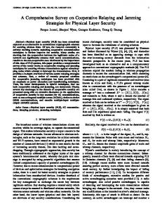
Fig. 13 shows the results that we achieved by analyzing and simulating the 2-phase cooperation protocol presented in Fig. 4. Except for the O-marked plot, corresponding analytic and simulation results closely match and show the behavior known from outage analysis [14, 10, 17]. Here, the strong decrease in PER compared to direct transmission clearly indicates the high diversity gain introduced by 2-phase SD&F cooperation protocols. This behavior, well-known from theory, and the close match to the analytic results clearly justify the simulation results of the ◦-marked protocol. However, this is not the case for the O-marked protocol, which was our first design step. The results obtained for this protocol show that the progression beyond 0 dBm deviates from theoretical analysis, as the slope declines. This can be explained by understanding what happens upon successful transmission in the first phase. In this case, the source uses the second phase to transmit successive data. Retransmission by a relay is not possible then because the protocol defines that the relay only overhears data during the first phase and retransmits it in the second phase. Therefore, the source’s transmission in the second phase does not benefit from user cooperation diversity. If, however, the protocol is changed such that the source refrains from transmitting in the second phase, we achieve the ◦-results. Now, every transmission can be possibly overheard and retransmitted by the partner. While the two-step design iteration could have been avoided for this simple protocol, it clearly demonstrates the power of our approach for more complex protocol designs where the implications of the design may not be as obvious beforehand. If simulation results turn out to be other than expected, the cause is likely due to the
−4
10
−5
10
−6
10
EVALUATING COOPERATIVE PROTOCOLS
In this section, we compare analytic and simulation results to justify our simulation framework. For this comparison, we study basic SD&F cooperation protocols for which analytic results can be derived using the methods from [10]. An implementation of such a simple 2-phase cooperation protocol, which we introduced as an example in Section 3.2 and formally specified in Section 3.4, was generated by following the methodology suggested in this paper for OMNeT++/Mobility Framework. The implemented protocol runs on top of our IEEE 802.11a PHY model (Section 2) at a carrier frequency of 5.2 GHz at 20 MHz bandwidth. The channel model (Section 2) is parameterized with a path loss exponent of 2.4, a maximum Doppler spread according to a velocity of v = 1 m/s, and no shadowing. The three users, source, destination, and relay, are symmetrically placed, each 20 m apart. Each user transmits with the same power Ptx that is varied from -20 to 20 dBm. We assume a constant bit rate traffic stream corresponding to the download of a large file.
−3
10
−7
10 −20
Direct (simulation) Direct (analysis) Cooperative / own data in ph. 2 (simulation) Cooperative / relay only in ph. 2 (simulation) Cooperative (analysis) −15
−10
−5 0 5 10 Transmission power Ptx [dBm]
15
20
Figure 13: Comparing simulation and analytic results for direct and cooperative transmission in a symmetrical three-users scenario. The curves for direct transmission are identical.
specification. For any specification, the generated code is correct in the sense that it obeys the semantics of the specification (assuming the translation phase of the compiler has been shown to be correct). Only the subsequent fine-tuning by hand remains error-prone, but to a less extensive degree. By carefully observing the results, developers can then adequately change the specification, generate a new simulator, and re-run simulations in the same scenario to analyze the consequences of their changes. Thus, this section showed that the compiler-assisted approach suggested in this paper is justifiable in practice.
6.
CONCLUSIONS
In this paper we showed a new methodology for developing cooperative relaying systems. Our approach consists of suitable channel and PHY models, a new specification language to formalize system design, which then enabled us to develop a compiler for the generation of robust implementations. We hope that our approach allows developers to evaluate specific designs for cooperative relaying systems easier and faster. Of course, there is a trade-off associated with the compiler-assisted approach that we suggest in this paper. The development of a new specification language and a suitable compiler comes at a cost. Developers must firstly learn how to use the language, and secondly they must develop a backend for their target platform. However, these costs will pay off since a myriad of factors and methods exist and affect system design, e.g., relating to partner selection, rate adaptation, or traffic awareness. By using a specification language, evaluation not only becomes faster and more convenient, it also becomes more comprehensible by the community. When new patterns for cooperative relaying are invented and specified in a commonly used specification language, performance results can be easily transferred to other environments, e.g., from a simulator to an SDR. Developers are not forced to use a particular environment, but can simply generate a pattern’s code for the environment that they are fond to use. In conclusion, the compiler-assisted approach can provide a solid basis for the spread and growth of cooperative communications.
Best Paper Award
In Proc. Intl. Conf. on Simulation Tools and Techniques for Communications, Networks and Systems (SIMUTools), Mar. 2008
7.
REFERENCES
[1] J. Cavers. Mobile Channel Characteristics. Kluwer Academic, 2000. [2] Y. Chen, S. Kishore, and J. Li. Wireless diversity through network coding. In Proc. IEEE Wireless Communications and Networking Conference (WCNC), volume 3, pages 1681–1686, Apr. 2006. [3] W. Drytkiewicz, S. Sroka, V. Handziski, A. Köpke, and H. Karl. A mobility framework for OMNeT++. 3rd International OMNeT++ Workshop, Budapest University of Technology and Economics, Department of Telecommunications, Jan. 2003. [4] R. W. Gray, S. P. Levi, V. P. Heuring, A. M. Sloane, and W. M. Waite. Eli: a complete, flexible compiler construction system. Commun. ACM, 35(2):121–130, 1992. [5] D. Gunduz and E. Erkip. Joint source-channel cooperation: diversity versus spectral efficiency. In Proc. IEEE International Symposium on Information Theory (ISIT), pages 392–392, June 2004. [6] T. E. Hunter, S. Sanayei, and A. Nosratinia. Outage analysis of coded cooperation. IEEE Trans. Inf. Theory, 52(2):375–391, Feb. 2006. [7] M. Janani, A. Hedayat, T. E. Hunter, and A. Nosratinia. Coded cooperation in wireless communications: space-time transmission and iterative decoding. IEEE Transactions on Signal Processing, 52(2):362–371, Feb. 2004. [8] U. Kastens, A. M. Sloane, and W. M. Waite. Generating Software from Specifications. Jones and Bartlett Publishers, 2007. [9] A. Köpke, M. Swigulski, K. Wessel, D. Willkomm, P. T. K. Haneveld, T. Parker, O. Visser, H. S. Lichte, and S. Valentin. Simulating wireless and mobile networks in OMNeT++: The MiXiM vision. In Proc. Intl. Workshop on OMNeT++ (co-located with SIMUTools ’08), Mar. 2008. [10] J. N. Laneman, G. W. Wornell, and D. N. C. Tse. Cooperative diversity in wireless networks: Efficient protocols and outage behavior. IEEE Trans. Inf. Theory, 50(12):3062–3080, Dec. 2004. [11] B. O’Hara and A. Petrick. IEEE 802.11 Handbook: A designers companion. IEEE Press, 1999. [12] T. Pawlak and S. Valentin. Chsim – A wireless channel simulator for OMNeT++. Project website: http://wwwcs.upb.de/cs/chsim, 2006. [13] J. G. Proakis. Digital Communications. McGraw-Hill, 4 edition, 2000. [14] A. Sendonaris, E. Erkip, and B. Aazhang. Increasing uplink capacity via user cooperation diversity. In Proc. IEEE International Symposium on Information Theory (ISIT), page 156, Aug. 1998. [15] M. K. Simon and M.-S. Alouini. Digital Communications over Fading Channels. John Wiley & Sons, Inc., 2 edition, 2004. [16] S. Valentin and H. Karl. Analyzing the effect of asymmetric mobility and channel configurations on the outage performance of coded cooperative systems. In Proc. of the European Wireless Conference (EW), Apr. 2007. Invited Paper.
[17] S. Valentin and H. Karl. Effect of user mobility in coded cooperative systems with joint partner and cooperation level selection. In Proc. IEEE Wireless Communications and Networking Conference (WCNC), Mar. 2007. [18] A. Varga. The OMNeT++ discrete event simulation system. In Proc. of the European Simulation Multiconference (ESM’2001), 2001. [19] S. A. Zummo. Performance analysis of coded cooperation diversity in wireless networks. Wireless Communications and Mobile Computing, July 2006.
APPENDIX EBNF Specification of MPDL This section formally specifies the version of the domain-specific language MPDL used in this paper in an Eli-compatible Extended Backus-Naur Form (EBNF). The starting production is MPDLSpec. Terminal symbols of the grammar are Numeric for Pascal-like integers, and Identifier for Ada-like identifiers. This grammar only allows for lexical and syntactic analysis of specifications in MPDL. In addition, transformation requires an attributed grammar which is not shown here.
MPDLSpec: Dcls. Dcls: Dcls ’;’ Dcl / Dcl. Dcl: DclRole / DclFrame / DclPattern / DclSpacing. DclRole: ’role’ (RoleId // ’,’). DclFrame: ’frame’ (FrameId // ’,’) FrameBody. DclPattern: ’pattern’ PatternId ’at’ RoleId Stmt. DclSpacing: ’spacing’ SpacingId Numeric. FrameBody: ’like’ FrameId / ’{’ (Prop // ’,’) ’}’. Prop: PropertyName ’=’ PropertyValue. PropertyName: Identifier. PropertyValue: Identifier / Length. Length: BitsValue / BytesValue. BitsValue: Numeric ’bits’. BytesValue: Numeric ’bytes’. HBody: ’{’ Handlers ’}’. Handlers: Handlers ’;’ Handler / Handler. Handler: ’on’ FrameId ’at’ RoleId Stmt [’else’ Stmt]. After: ’after’ SpacingId. Stmt: ’send’ FrameId ’to’ RoleId [After] HBody / ’waitfor’ FrameId [HBody] / NoHBodyStmt [After]. NoHBodyStmt: ’done’ / ’reset’ / ’retry’. FrameId: Identifier. RoleId: Identifier. PatternId: Identifier. SpacingId: Identifier.
Best Paper Award