Implementing Multi-Viewer Stereo Displays Bernd Fröhlich, Jan Hochstrate, Jörg Hoffmann, Karsten Klüger
Roland Blach Matthias Bues
Oliver Stefani
Bauhaus University Weimar
CC Virtual Environments Fraunhofer IAO
Center of Applied Technologies in Neuroscience
Bauhausstraße 11
Nobelstr 12
Wilhelm Klein-Strasse 27
99423 Weimar
70569 Stuttgart
4025 Basel,
Germany
Germany
Switzerland
Bernd.Frö
[email protected] [email protected] -weimar.de
[email protected]
ABSTRACT In this paper we describe our implementations of multi-user stereo systems based on shuttered LCD-projectors and polarization. The combination of these separation techniques allows the presentation of more than one stereoscopic view on a single projection screen. We built two shutter configurations and designed a combined LC-shutter/polarization setup. Our first test setup was a combination of mechanical shutters for the projectors with liquid crystal (LC) shutters for the users’ eyes. The second configuration used LC-shutters only. Based on these configurations we have successfully implemented shuttering of four projectors to support two users with individual perspectively correct stereoscopic views. To improve brightness conditions and to increase the number of simultaneous users, we have designed a combined LC-shutter/polarization filter based projection system, which shows the most promising properties for real world applications.
Keywords Virtual Reality, Immersive Projection Systems, Stereo Displays, Multi User Systems, Multi Viewer Systems
1. INTRODUCTION Perspective projection in combination with head tracking is widely used in immersive virtual environments to support users with correct spatial perception of the virtual world. However, most projection based stereoscopic systems show a correct perspective view for a single tracked viewer only. Other users share the same view, but from different positions, which results in an incorrect perception of the displayed objects. This limits the suitability of Permission to make digital or hard copies of all or part of this work for personal or classroom use is granted without fee provided that copies are not made or distributed for profit or commercial advantage and that copies bear this notice and the full citation on the first page. To copy otherwise, or republish, to post on servers or to redistribute to lists, requires prior specific permission and/or a fee. WSCG 2005 conference proceedings ISBN 80-903100-7-9 WSCG’2005, January 31-February 4, 2005 Plzen, Czech Republic. Copyright UNION Agency – Science Press
projection-based stereoscopic systems for multiviewer scenarios, particularly in cases where concurrent 3D-interaction of all users is desired. Our intent is the development of a multi viewer projection system for local collaboration in immersive environments. We focus on projection based systems where all users operate in the same interaction space. A realistic application scenario for a team of collaborators in front of a single projection screen would incorporate not more than ten users due to space limitations in front of the screen. In most cases we expect only two to six users being involved in such scenarios. In this paper we describe our implementations of multi-user stereo systems based on shuttered LCDprojectors and polarization. We discuss the results of our work and give a comparison of the three configurations. Additionally, our ideas for further improvement will be presented.
View Separation Techniques The separation of different views is mainly used to separate the left eye view from the right eye view in stereo projection systems. There have been also examples for the separations of different user perspectives [Agr97, Blom02]. Following the classification of Paastor [Paa97] for separation techniques we will describe the common approaches in the field of immersive projection environments.
1.1.1 Time-Sequential or Shutter Techniques There are two main approaches for shuttering projectors: mechanical shutters and liquid crystal (LC) shutters. Mechanical shutters are in the simplest form based on a spinning disc, which is half transparent and half opaque. [Fak04, Ham24, Lip01, Pal01] suggest this approach, which also seems to be used in a commercial product [Fak04]. Liquid crystal shutters are widely used for shutter glasses and they were also used for shuttering projectors [Kun01, Kun02]. They can be opened and closed electronically.
1.1.2 Color-Multiplexing Anaglyphs, a common technique for stereo viewing, use different colors to provide different views. The perceived image appears monochrome. From the ergonomical point of view anaglyphs are more tiring and they are more straining for the eyes than other techniques. A new approach has been developed which is based on wavelength multiplexing which is a kind of multi channel color multiplexing for red, green and blue, the so called Infitec system [Jor04]. With this approach there are up to now some inherent problems with color matching delivered in the different views. Color multiplexing uses appropriate filters in front of the projector and the eyes for the separation.
1.1.3 Polarization-Multiplexing Polarized light has a defined oriented field vector in the plane perpendicular to the direction. Linearly polarized light has fixed direction. Circularly polarized light has a fixed rotation direction of the field vector. With appropriate filters, polarized light can be generated from unpolarized or undirected light. With polarization it is only possible to separate two views due to the nature of polarization where the filtering is based on the splitting of the light waves into two orthogonal parts. A linear polarization filter which is orthogonal to the light polarization direction theoretically blocks the light completely. Polarization filters are used in front of the projectors and the eyes to apply the separation. This is the standard technique for stereo projection in non interactive mass presentations.
1.1.4 Performance parameters To evaluate the quality of a multi view projection system, three main parameters can be considered: •
Brightness per view
•
Crosstalk; static and dynamic
•
Perceived flicker, which depends on the shutter frequency, the video rate of the projector and brightness.
One of the main challenges is the delivery of sufficient light to the eye. The light which is emitted by the projection system is distributed over the amount of views and is therefore dependent on the overall view switching frequency, the initial brightness and the attenuation of the optical filter. Another issue is crosstalk between different views which is generally disturbing and also strains the eyes. Crosstalk occurs when image parts belonging to other views are perceived, which should be ideally completely blocked. Crosstalk can be subdivided into static and dynamic crosstalk. Static crosstalk is based on the imperfection of the used materials. In the case of shutters the contrast ratio, that is the ratio between transmission in the open state to transmission in the closed state, is also an indicator for expected static crosstalk. Dynamic crosstalk is due to the timing behavior of the opening and closing of the shutter elements and only arises in the transition phases. Dynamic crosstalk can be reduced to nearly not existent with an adequate control system. In a system with low switching frequency, there will be always a trade off between dynamic crosstalk and brightness. Our approach for the configuration of a scalable multi view system focuses on a hybrid configuration which combines shutter and polarization filter techniques.
2. RELATED WORK Shuttering devices for time-sequential stereoscopic displays have a long history. Lipton provides an overview in [Lip91]. Interesting in this context is Lipton’s reference to Hammond’s work on the Teleview system from 1924 and 1928 [Ham24, Ham28]. Hammond used a spinning disc and two projectors to generate a field-sequential active stereo image. He also used a synchronized spinning disc in front of the user’s eyes to provide each eye with the corresponding image. Palovuori’s patent application from 2001 [Pal01a] presents basically the same approach based on the spinning disc and shows nearly identical images. In addition, Palovuori suggests the use of LC shutters in front of the users’ eyes and/or in front of the projectors. Palovuori’s patents also mention the extension of the shuttering approach to more than two projectors, which he calls multichannel images. In [Pal01b] Palovuori suggests
the development of pulsed projectors, which emit bright images only during their active cycle. They are dimmed down or turned off during the rest of the time. The application of polarization filters for stereo viewing systems was used since 1936, when three approaches were discovered for the economical and industrial production of polarization filters (Bernauer, Kaesemann, Land and Mahler). Thus, picture separation became possible even in color pictures [Waa85]. The technology has not changed much since. The main issues were the loss of light by the filter and crosstalk. Recently, new approaches for better exploitation of light for LCD-projectors was presented [Elk02, Ste05]. Kunz et al. [Kun01, Kun02] employed LC shuttered LCD-projectors to generate an active stereo display for their blue-c system. There have been a small number of other approaches to provide multiple users with individual stereoscopic images. The two-user Responsive Workbench [Agr97] displays four different images in sequence on a CRT-projector at 144Hz, which results in 36Hz per eye per user. They also developed custom shutter glasses for cycling between four eyes. Blom et al. [Blo02] extended this approach to support multi-screen environments such as the CAVE [Cru93]. Barco [Bar04] developed the “Virtual Surgery Table”, which provides two users with individual stereoscopic images by combining shuttered and polarized stereo into one system.
3. PROJECTION SETUPS We describe three configurations which combine the polarization and shutter separation techniques.
A multi view setup which operates with shutters and polarization filters can be described schematically as follows:
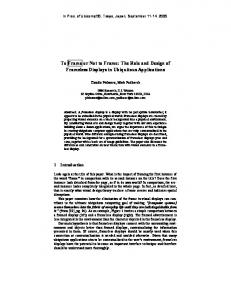
Figure 2. General multi view setup with shutter and polarization filter; left and right view of user 1 are active.
As described in [Agr97, Blo02] for pure shutter systems, there are basically two different open/close sequences; user interleaved or eye interleaved that is AL, AR, BL, BR, CL, CR, … or AL, BL, CL, AR, BR, CR, … (A, B, C are user indices, L and R are left and right eye index).
Combined Mechanical and LC-Shutter For the mechanical shutter approach we used a spinning plexiglass disc in front of the projectors. For safety reasons the spinning disc is encased in a wooden cage (Figure 3).
General Setup Considerations A multi view setup which operates only with shutters can be described schematically as follows:
Figure 3: The spinning disc is contained in a wooden cage separated from the projector rack to avoid vibrations of the projectors. The small motor in the middle spins the disc.
Figure 1. General multi viewer setup based on shutters. The right eye of user 1 is active.
The straight forward layout for the spinning disc would use three opaque quarters and one transparent quarter. If we open the shutters immediately once the transparent quarter reaches a lens, we introduce crosstalk since one of the other lenses is still open. If we reduce the transparent quarter such that it fits right in between the projector lenses such that only
one lens is open at a time, we reduce the crosstalk significantly (Figure 4). The overall brightness is appropriately reduced. Alternatively we could stick with the ¾ / ¼ and open shutters only during times when only one projector lens is open. This introduces phases during which all shutter glasses are closed. Other layouts are possible, which divide the disc for example into eight zones. Two zones would be transparent, the others opaque. Such a setup would divide the required rotation speed in half, but decreases the actual light output if the disc size is not enlarged. The diameter of the exit pupil of the projectors in relation to the circumference of the disc should be small, since the actual shutter timing depends directly on it.
Figure 4. Shutter disc for the two-user setup. Four projectors are located around the axis of the disc. One quarter of the disc is open, three quarters are closed. A reflective optical switch is used for generating the synchronization signals for the shutter glasses.
We currently use a single reflective optical switch to generate the control signals for the shutters. The inner ring of the disc is separated into four black and four white zones, which generate the clock for the shutter glasses. Our current implementation requires that the spinning disc starts always in a defined orientation to switch the LC shutters in the correct order. We could also install an additional optical switch which detects the opening of the first video projector and provides an initialization for the clock signals of the inner ring. We use the ATMEL ATMega32 [Atm04] micro controller to drive the shutter electronics for the projectors and glasses. The amplified digital outputs of the micro controller are used to drive the shutter glasses. The digital inputs read the signals from the reflective optical switches.
LC-Shutter We used standard tethered gaming shutter glasses (Elsa Revelator) for shuttering the users’ eyes. For shuttering the projectors we took the same gaming
shutter glasses apart and mounted the shutters directly in front of the projectors. The shutters are a little too small to cover the whole image, but for a test setup they were quite sufficient. The original electronics of the shutter glasses were removed and we used also the ATMEL ATMega32 micro controller to generate the required signals. LC-shutters are closed if a positive or negative voltage is applied. Otherwise they are open. For fast and continuous on/off switching of the shutters it is necessary to drive them with alternating polarity to avoid memory effects. Our experiments showed that our particular shutters provide the best results if +-15 Volts are applied. We were able to run the shutters at up to 300Hz with only little cross talk. Currently we feed exactly the same signal to the shutters in front of the projectors and to the shutter glasses. As a consequence, the closing signal for a projector and the corresponding eye shutter arrive exactly at the same time as the opening signal for another projector and eye. This approach might contribute slightly to the cross talk, but we have not yet experimented with slight delays nor do we know the exact open and close timing behavior of the shutters. For the final tests we used projectors with 1700 Lumens, which resulted in significant heat development in the shutters. We had to install a fan to cool the shutters down. Larger shutters would allow us to move away from the LCD-projectors, which would distribute the heat across the larger shutter surface. Smaller fans could be mounted near each shutter to avoid heat problems..
Combined LC-Shutter and Polarization For the combination of polarization and the LCShutter approach, two solutions are possible: •
Eye separation with shutters and user separation with polarization
•
Eye separation with polarization and user separation with shutters
The second approach scales well, since users can be added one by one. For the maximum exploitation of light we used LCD-projectors with an extension of the filter optimization proposed by Stefani [Ste05]. Due to their internal structure most LCD projectors emit already linearly polarized light. Unfortunately, the polarization of the green beam is orthogonal to the polarization of red and blue beam. This problem can be solved by wavelength dependent λ/2 retarders for the green channel and a red/blue combination, which rotates only the appropriate color channels by 90 degrees. These selective retarders can be obtained from projector filter manufacturers, e.g. ColorLink [Col04].
LC-Shutter elements use also polarization filter as an integral part of their function. A LC shutter is a combination of two linear polarizers and a voltage controlled retarder. For a single user the light path is shown in Figure 5.
4. DISCUSSION We have evaluated the different setups regarding brightness, crosstalk and subjective perception of flicker. We are aware of the difficulty of comparing these setups formally. Nevertheless, they show the principles with their advantages and disadvantages very clearly.
Brightness considerations We have measured the relative brightness of filter combinations which can be applied to the various configurations. For the measurement we used the Panasonic LB 10-NTE LCD-projector with 2000 ANSI lumens. As measurement device we used the Universal Photometer from Hagen. The following optical elements were used: Element
Description
Figure 5. The polarized light is emitted from the projector. A selective green λ/2 retarder rotates the green channel on the upper projector. A selective red/blue λ/2 retarder rotates the red and blue channel on the lower projector. The LC-shutters are then applied to open and close the views. All shutters for one user are opened and closed at the same time.
LCS
LC-Shutter element Crystal Eyes 1
PL
Linear polarization filter heliopan ES 77
RL2
Retarder λ/ 2
RL2g
Selective Retarder for green λ/2
We plan to use ferroelectric liquid crystal (FLC) shutters for the user separation, which are significantly faster than standard LC shutters. FLCshutters have to be driven differently than the above mentioned Elsa Revelator Shutters, which we also drive by an ATMEL microcontroller.
CRPL
Combined high quality element consisting of a selective λ/2 retarder, a λ/2 retarder, and a linear polarization filter
Stereographics
Table 1: Used Elements in measurement.
We present here the results which are the building blocks for the three presented hardware combinations.
23,66%
equivalent DLP config
LC-Shutter without polarization modification LCS + LCS, 45°
21,57% 29,03%
LC-Shutter with polarization modification not optimized
35,48%
equivalent DLP confiig
LC-Shutter with polarization modifications, optimized Element
Linear Polarization CRPL
35,29%
75,27%
Figure 6. Combined LC-Shutter and Polarization Setup. View of user 1 is shown all others are closed.
In this configuration, four LC-Shutters are used for one user. All four shutters open and close at the same time. We have to trigger the next user after the shutters of the previous user are definitely closed to avoid cross talk. As projector we will use the Panasonic LB 10-NTE with 2000 ANSI lumens. For this setup a fan was also necessary to cool the optical elements.
0,00%
10,00%
20,00%
30,00%
40,00%
50,00%
60,00%
70,00%
relative brightness
Figure 7. Relative brightness with a white test pattern. The DLP is shown only for comparison as a representative for non polarized light sources. The last row shows a optimized standard polarization.
The pure LC-shutter setup and the combined LCshutter/polarization setup follow the same light path. Consequently the pure LC-shutter configuration can also benefit from the modification and optimization with the CRPL Element as a prefilter in front of the projector shutter. Nevertheless the combination of
80,00
shuttering and polarization provides twice the brightness as the shutter only approach, but it requires a polarization preserving projection screen.
Combined Mechanical and LC-Shutter The spinning disc approach leads to really fast rotations if it is used in its simplest form. For example if we want to achieve 200Hz, 50Hz per eye per user, we need to spin the disc at 50 Hz or 3000 rpm. We tried this approach and we were able to spin the disc at up to nearly 3000 rpm with a small DC motor. At the maximum rotation rate and 49.5 Hz per eye per user the image was basically flicker free. At 45Hz we saw minimal flicker. At lower refresh rates the flicker increased and below 40Hz the flicker was very noticeable. Our current disc has a diameter of around 40 Centimeters and is made of 3mm plexiglass. The minimal size of the disc is mainly determined by the size of the projectors and the distances of the projector lenses, but the disc size affects directly the time it takes to close and open a projector lens. Larger discs reduce this time significantly, but it is difficult to fully avoid vibrations and noise of large spinning discs. We did not measure the noise of our system, but it was significant and annoying after a while. The cage around the spinning disc could be used to dampen the noise. One of the main advantages of the mechanical shuttering approach is the possibility to completely avoid static crosstalk between projectors. There is always some cross talk due to the shutter glasses unless they would be replaced by mechanical shutters as well. Thus it is very worthwhile to look at mechanical shuttering systems, which provide 100% transmittance during their open period even though the LC shuttering approach is much easier to implement.
LC-Shutter Our first tests investigated the cross talk at different frequencies and supply voltages for the LC-shutters. The least cross talk was found at about 15 Volts. Over 15 Volts the shutters started to show some speckles, which indicates their voltage limitations. Nevertheless we were running the shutters at 15 Volts for many hours without any degradation in image quality, but it is possible that this is above the specs. There was slight crosstalk, which was barely perceivable while viewing stereoscopic images. Our shutters are quite small and they barely cover the exit pupil of the projector lens. If we use the full resolution of the projectors, we are seeing refraction artifacts from the boundaries of the shutters, which results in some rainbow effects across the images. If we limit ourselves to about 80 percent of the shutter surface, these artifacts are no longer visible.
We experimented with different shutter switching frequencies in the range of 140Hz to 400Hz. We implemented the timing control for two, three, and for users. For two users, each shutter (eye) was open for one fourth of the time, for three users for one sixth, and for four users for one eighth. The tests were performed with two pairs of glasses and four projectors, but the timing was already correct for two, three and four users. The results of these tests: Two User
Three User
Four User
140 Hz
flickering
160 Hz
Very little flicker
200 Hz
no flicker
240 Hz
No flicker, good image
slight flicker
flickering
280 Hz
No flicker, Very good image
barely flickering
Slight flicker
300 Hz
(270 Hz) No flicker very slight flicker
320 Hz 360 Hz
dark image, pumping
Dark image
Table 2: Flicker impressions
Above 320Hz our shutters did not open fully anymore and the images got quite dark. At around 400 Hz the shutters started to show some stripe patterns and did not work properly anymore. It was amazing to see that these cheap LC-shutters worked quite well even at such high frequencies. For the two user scenario, our favorite frequency was 280Hz, which resulted in a stable and completely flickerless image. But even at 160 Hz the flicker was not really very disturbing, but we did not use the system for long working periods. We did not perceive any difference in brightness between 160Hz and 280Hz for two users, even though the state transition time of the shutter glasses should start to play a role. In particular the transition from the closed to open state is longer than the inverse transition. For three users, the image was slightly darker than for two users, since each eye was exposed to an image for only one sixth of the time. There was little flicker above 270Hz. For four users, the image was clearly darker and there was still slight flicker at 320Hz. At higher shutter frequencies the image got much darker, and it was hard to judge the image quality. We have also investigated two different sequences of presenting the images to the left and right eye of each
user – similar to the approach in [Agr97]. The viewer interleaved sequences display the left eye images of all users in sequence and then the right eye images. The viewer sequential method displays the left and right eye images for each user directly in sequence. Surprisingly, we did not notice any perceivable differences, even when switching directly back and forth.
Combined LC-Shutter and Polarization It is obvious that proper orientation of shutters in front of the projector and in the glasses immediately leads to the desired polarization. The only difference to a purely shutter based approach is a different controller scheme for the shutters. The benefit is we need only half the shutter frequency and obtain double brightness. The FLC-shutters have much faster switching times than the Elsa revelator glasses, but they are also much more expensive. For real world configuration it will depend on the number of users. Based on the measurements a four user setup might already be possible with the Elsa-Shutter.
shutter system can be independent from the computer graphics hardware, because no tight coupling of frame buffer swaps and shutter activity is necessary. Previous approaches have mainly used quadbuffer stereo and active stereo components [Agr97][Blo02] where such a synchronization is necessary. Shutter techniques as described here can also be easily combined with color multiplexing for left and right view separation. If the Infitec separation has overcome its color reproduction problems, it might be a powerful alternative to polariziation techniques.
Driving Software The projection systems were driven by two different software systems Avango [Tra99] and Lightning [Bla98]. Both application frameworks are capable to support multiple views on multi pipe machines or on clusters in a very generic way. We implemented some basic test scenarios on both frameworks, which were basic 3D object viewers.
As of now, we only have used this configuration for pure proof of concept and have not built an entire working environment. So far our experiments look promising and they are confirmed by our measurements. Nevertheless. formal results can only be obtained with a working setup with more than two users.
General Remarks on shutter techniques When using LC-shutters in front of a LCD-projector one can benefit from the optimized optical elements described above. One advantage of a pure shutter configuration is that in principle it is not necessary to use a polarization preserving projection surface. The consequence is also that when depolarized on the projection surface, the system has no rotation restrictions anymore. The trade off is very low brightness. An equivalent for the polarization approach is the introduction of retarder (λ/4) in the open light path to obtain circular polarization, which is also rotation invariant It is important to notice the relation between the shutter element and the actual image formation inside the projection. As long as the shutters are not synchronized with the video signal, artifacts as image tearing or irregular flicker can occur. Also the usage of color wheels will introduce color artifacts. Off the shelf LCD-projectors seem to be very appropriate because they follow a three LC-chip approach and they are also slow enough to preserve the color information in the LC-cell until the next image will be generated. Presenting the views with independent projectors has the nice property that the synchronization of the
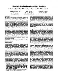
Figure 8. An image taken directly from the projection screen. It shows four images overlayed on top of each other. Two images are displayed for the left user's eyes and the other two images for the right user's eyes.
5. CONCLUSIONS AND FUTURE WORK We have shown that multi view environments with more than two users are feasible and can be realized with a reasonable amount of hardware. Three different setups have been presented and discussed. The combination of LC-shutter and polarization has a shown to be the most promising approach considering scalability and brightness. An interesting approach to enhance the projector shuttering is the usage of a pulsed light source which is synchronized with the users glasses which has been mentioned already in [Pal01b]. Major advantages are better exploitation of light, static crosstalk on projector side can be minimized to not existent because of best contrast ratio and dynamic crosstalk is not depending on mechanical properties of the shutter. It is a combination of the contrast properties of mechanical shuttering with the control properties of fast LC-shutters. Stroboscopic light
bulbs or LED-Technology might be an interesting path to follow. We have experimented with a high luminous LED array. Some issues are already obvious: heat, beam guidance and the bundling of the light. Besides further technical optimizations, we want to integrate known collaborative 3D-interaction tools and develop adapted tools for the new situation of local 3D-collaboration in the same interaction space.
6. ACKNOWLEDGMENTS The micro controller board was developed within the VRIB project, which was funded by the German government. We thank David Paneque and Alexander Kulik for partly building the various shuttering setups.
7. REFERENCES [Agr97] Agrawala M., Beers A., Fröhlich B., Hanrahan P., McDowall I., Bolas M.: The TwoUser Responsive Workbench: Support for Collaboration Through Individual Views of a Shared Space, Computer Graphics (SIGGRAPH '97 Proceedings), volume 31, pp. 327–332, 1997. [Atm04] Atmel AVR microcontroller http://www.atmel.com/products/AVR/ [Bar04] Barco: Virtual Surgery Table. http://www.barco.com/VirtualReality/en/products /product.asp?element=523 [Bla02] Blach R., Landauer J., Rösch A, Simon A., A Flexible Prototyping Tool for 3D Real-Time User-Interaction. Proceedings of the Eurographics Workshop on Virtual Environments 98 , 1998 pp. 195-203 [Blo02] Blom K., Lindahl G., Cruz-Neira C.: Multiple Active Viewers in Projection-Based Immersive Environments. Immersive Projection TechnologyWorkshop, March 2002 [Cru93] Cruz-Neira, C., Sandin, D.J., and DeFanti, T.A. Surround-screen Projection-based Virtual Reality: The Design and Implementation of the CAVE. Proceedings of SIGGRAPH '93, 135142, 1993. [Col04] Colorlink Filter http://www.colorlink.com/products/pdfs/select.pd f [Elk02] . Elkhov V.A, Ovechkis J.: Light loss reduction of LCD polarized stereoscopic projection, Stereoscopic Display and Virtual Reality Systems X , Proc. of SPIE Vol. 5006, pp. 45-48, 2003 [Fak04] Fakespace Systems: Active Stereo Digital Projection Technology http://www.fakespace.com/05162003.htm
[Ham24] Hammond L.: Stereoscopic Motion Picture Device. U.S. Patent No. 1,506,524, Aug. 26, 1924. [Ham28] Hammond L.: Stereoscopic Picture Viewing Apparatus. U.S. Patent No. 1,658,439, Feb. 7, 1928. [Jor04]. Jorke H., Fritz M.: INFITEC - A new Stereoscopic Visualisation Tool by Wavelength Multiplex Imaging, Electronic Displays [Krü94] Krüger, W., and Fröhlich B. The Responsive Workbench. IEEE Computer Graphics and Applications, 12-15, May 1994 [Kun01] Kunz A., Spagno C.: Novel Shutter Glass Control for Simultaneous Projection and Picture Acquisition. Immersive Projection Technology and Virtual Environments 2001, Stuttgart, Germany, May 2001, pp. 257-266. [Kun02] Kunz A., Spagno C.: Technical System for Collaborative Work. EGVE 2002, pp. 73-80; May, 30-31 2002 [Lip91] Lipton L.: Selection devices for fieldsequential stereoscopic displays: a brief history. Proc. SPIE Vol. 1457, p. 274-282, Stereoscopic Displays and Applications II, John O. Merritt; Scott S. Fisher; Eds. Aug. 1991. [Lip01] Lipton L.: The Stereoscopic Cinema: From Film to Digital Projection, SMPTE Journal, pp. 586-593, Sept 2001 [Pal01a] Palovuori, Karri: Apparatus based on shutter function for projection of a stereo or multichannel image. Patent number: WO03003750, http://v3.espacenet.com/textdoc?DB=EPODOC& IDX=WO03003750 [Pal01b] Palovuori, Karri: Apparatus based pulsing for projection of a stereo or multichannel image. Patent number: WO03003751, http://v3.espacenet.com/textdoc?DB=EPODOC& IDX=WO03003751 [Paa97] Paastor S., Wöpking M.:3 -D Displays: A review of current technologies, DISPLAYS, 17, pp. 100-110, 1997 [Ste05] Stefani O., Bues M., Blach R: Low-loss filter for stereoscopic projection with LCDprojectors, to appear in Proc. of SPIE Vol. 5008, 2005 [Tam99] Tramberend, H. Avocado: A Distributed Virtual Reality Framework. Proceedings of VR’99 Conference, Houston, Texas, 14-21, March 1999. [Waa85] Waack, F.G., Stereo Photography, London pp.72