Implementing Rotor Field Orientated Control and Direct Torque Control of FivePhase Induction Motor Using TMS320C32 DSP Huangsheng Xu
Hamid A. Toliyat
Electric Machines & Power Electronics (EMPE) Laboratory Department of Electrical Engineering Texas A&M University College Station, TX 77843-3128 Phone: (979) 862-3034 Fax: (979) 845-6259 E-mail:
[email protected]
Abstract: This paper presents rotor field orientated control (RFOC) and direct torque control (DTC) of the five-phase induction motor, and their fully digital implementation based on the TI's TMS320C32 DSP. RFOC and DTC, two important motor control methods, are extensively used in induction motor drives. Both of them are achieved by directly controlling motor flux and torque, which results in a fast dynamic response and high performance. A 32-bit floating-point TMS320C32 DSP allows these two kinds of sophisticated control techniques to be conveniently implemented with low cost and high control precision. Experimental results demonstrate that a very good control performance is obtained with the combination of RFOC and DTC with TMS320C32 DSP. It suggests that a floatingpoint DSP has a great practical prospect in motor drives. Keywords: TMS320C32 DSP; five-phase induction motor; rotor field orientated control (RFOC); direct torque control (DTC).
I. Introduction Digital signal processors have been widely applied in motor drives. When TMS32010 was initially introduced in 1982 by Texas Instruments, it was immediately applied to motor drives as its control-orientated version of the chip, TMS320C14. For years, DSPs have been expanded swiftly, C20, C24X, C25, C3X, C50 have been successfully developed and applied into motor drives. C24X, a 16 bit fixed-point DSP core with micro-controller peripherals in a single chip, is specifically designed for the digital motor control. The 32-bit floating-point C3X DSP is also widely adopted in motor drives. Due to their high processing speed, powerful instruction sets, innovative hardware architecture and low cost, DSPs have been a strong opponent to microprocessors like 80c31, 80c51 and 80c196Kx etc. With the advent of a large amount of novel features, such as floating point calculations, multiprocessing, embedded A/D and D/A converters, high level compiler and friendly manmachine interface, DSPs further make it simpler and more reliable to implement the sophisticated motor control techniques through software, and thus realize fully digital
high performance control systems for motor drives. Nowadays, DSPs have almost dominated motor control field replacing microprocessors and microcontrollers. Rotor field orientated control (FOC) and direct torque control (DTC) are two important motor control methods, and are extensively used in induction motor drives. They are implemented by directly controlling motor flux and motor torque, which make it possible that the dynamic and steady state performance of induction motor drives match or even surpass that of DC motor drives [1]-[4]. In this paper, the flux and torque of a five-phase induction motor with the combined fundamental and third harmonic of currents are studied. A corresponding rotor field orientated control of the five-phase induction motor is developed. The basic principle of RFOC of the five-phase induction motor is to decouple the stator currents ias , ibs , ics , ids , ies into flux components
id 1 , id 3 and torque components iq1 , iq 3 , and then to exert independent control on the flux and torque. RFOC of the five-phase induction motor has to generate the third harmonic current, which leads to a nearly square waveform flux distribution in the air-gap and the enhancement of output torque [5]-[7]. But it also brings about the control system much more complicated than the traditional RFOC of three-phase induction motors. In addition, the fundamental RFOC and the third harmonic RFOC should be coordinately adjusted in order to produce the desired flux distribution and increase torque output. Direct torque control of the five-phase induction motor is also presented here. It is well known that DTC of induction motors, which is based on instantaneous space vector theory, is a powerful motor control method. By optimal selection of the space voltage vectors during each sampling period, DTC achieves effective and direct control of the stator flux and torque instead of the conventional current control technique[8][9]. For the five-phase induction motor, DTC has its unique characters. DTC of the fivephase induction motor has the 32 space voltage vectors with the different amplitudes[10][11]. Compared with the 8 vectors of DTC of the three-phase induction motor, the increased number of voltage space vectors allows developing a more elaborate DTC algorithm, which
minimizes the ripples of the stator flux and torque, and hence achieves a more precise flux and torque control. In order to implement these two kinds of sophisticated control methods, RFOC and DTC of the five-phase induction motor, TMS320C32 DSP is adopted as the central processing unit. TMS320C32 is a low-cost member of TMS320C3x generation of 32-bit floating-point processors. The features of TMS320C32 reduce the chip and system costs, and increase system performance, making the advanced 32-bit floating-point architecture of the C3x DSPs available to a wide spectrum of cost-sensitive application. Operating from a 50 MHz clock a performance of 25 MIPS and a peak floating-point performance of 50 MFLOPS can be obtained, which executes RFOC and DTC algorithms with a high processing speed and precision. Furthermore, TMS320C32 comes with a highly effective and optimized C compiler, where all application softwares can be written in C. Once the simulation program using C language is finished, it can be directly transferred to DSP as a real-time control program without scaling calculations. Therefore, it is ideal to use it as a sole processor to develop a high-performance motor control system. Experimental results demonstrate that a very good control performance is achieved with the combination of RFOC and DTC and the TMS320C32 DSP, which suggests that a floating-point DSP has great practical prospect in motor drives.
II. Hardware Design of the Control System The DSP-based RFOC and DTC of five-phase induction motor has three interconnected modules, the C32 system board, 16I/O8 DSPLINK interface, and PWM outputs for a five-phase inverter drive application. The overall system block diagram is shown in Fig.1. TMS320C32 is the processing center of the RFOC and DTC system and achieves RFOC and DTC algorithms. DC Link voltage Ed , the stator currents ias , ibs , ics , ids , ies , and motor speed ω r are sampled and sent to the DSP through 16I/O8 DSPLINK interface. The voltage and currents are converted into digital forms by A/D and then input to the C32 DSP, while motor speed is directly input to DSP through digital lines. With this information, The DSP executes the RFOC and DTC program to generate PWM gating signals to drive the fivephase induction motor. The TMS320C32 used is a 50MHz 32-bit floating-point processor with two on-chip 32 bit timers, an enhanced external memory interface, a two channel DMA controller and a serial port. The functionality of the C32 board is illustrated in Fig.2, which offers a versatile and powerful development tool for motor drives. A detailed discussion of the architecture and programming of C32 is given in [12][13]. The main features of the board are discussed briefly here.
A bank of DPRAM provides a fast, continuous method of PC/DSP data exchange and a set of programmable registers from a control and status interface to the DSP, removing the need for hardware links. In addition to DPRAM, the C32 is provided with two banks of SRAM and a bank of EPROM. The SRAM is used for data storage and fast code execution. The EPROM stores embedded code to boot up the DSP and allows the C32 to function in a standalone environment.
Fig.1 Overall hardware architecture of control system.
The C32 board is also designed to interface to a number of on-board and off-board peripherals. These peripherals allow expansion of I/O capability of the C32 system. The interface can be chosen to suit the application requirements, such as: two LSI daughter modules (DM_A and DM_B) and DSPLINK interface. The later consists of a high speed, bidirectional bus that makes input/output directly to/from the C32 without using the I/O bus on the PC, and provides a high bandwidth, 32 bit, memory-mapped parallel expansion capability, which is used for data sampling and signal outputs for motor drives.
Fig. 2 C32 system board functional block diagram
16I/O8 multi-channel I/O DSPLINK module is directly connected to C32 DSP board through DSPLINK interface with a 50-pin IDC ribbon cable [14]. It provides a sixteen channel 12-bit analog to digital converter (ADC), an eight channel 12 bit digital to analog converter (DAC) and four digital output lines. Sampled data are transmitted to and received from the C32 system board via separate data registers over this 16-bit I/O DSPLINK interface, which also allows direct access to the programmable control functions
of the board. A functional block diagram of the 16I/O8 board is given in Fig. 3. 16I/O8 DSPLINK performs A to D and D to A conversions on all channels synchronously, asynchronously or independently. The A/D sample rate is up to 25kHz when all channels are being used, 38kHz when using eight channels and 48kHz when using four channels only. D to A may be performed at a maximum conversion rate of 100kHz when using the output channels only or 50kHz when using both the input and output channels. A programmable interrupt generator is also provided allowing the board to interrupt the C32 system board when, for example, 16I/O8 is ready to receive data to be converted. This comprehensive set of analog and digital inputs and outputs, coupled with good bandwidth, analog quality and low overhead operation, make the 16I/O8 DSPLINK an ideal DSP I/O subsystem for applications such as control systems, test and measurement, and general purpose data acquisition system.
than 10kHz. Therefore, the additional PWM hardware is designed.
Fig.4 PWM output block diagram
III. RFOC of the Five-Phase Induction Motor The basic principle of the rotor field orientated control of the five-phase induction motor is to divide the stator currents ias , ibs , ics , ids , ies into flux components id 1 , id 3 and torque components
iq1 , iq 3 , and then to exert independent
control on flux and torque like separately excited DC motor drives. On the q1 − d 1 − q 3 − d 3 coordinate system, suppose the rotor flux vector is aligned with the d reference frame. RFOC of the five-phase induction motor with the combined fundamental and third harmonic of current can be simply described by the following equations [15]-[18]: (1) λ dr1 = λ r1 = Lm1i ds1 ; λdr 3 = λr 3 = Lm3ids3 ; Fig.3 Block diagram of 16I/O8 DSPLINK board
The PWM hardware provides 10-channel accuracy PWM outputs. The outputs of the current PI regulators after being amplified are compared to a triangular waveform to generate 10-channel PWM signals, which are sent to the IGBT drive circuits (SKHI22) to form the five-phase inverter gating signals, and control the five-phase induction motor. SKHI22 assures a dead time of 2 µs between their gate signals of the upper and the lower devices to protect IGBTs in each leg from shoot through. Fault protection circuit monitors DC link over voltage (OV), stator over voltage, low voltage (LV), and over currents (OI), as well as motor over heat (OH) in real-time. Once one of these faults occurs, PWM outputs can be immediately blocked. Actually, PWM gating signals might be directly formed using the C32 DSP by software without the extra hardware. However, in this case, external interface is connected via 16I/O8 DSPLINK. No digital ports are directly output from the C32 DSP. Four digital output lines on the 16I/O8 board are not enough for the 10 channels of the five-phase PWM gating signals. Through D/A conversions, PWM output signals are distorted, and their frequency can not be more
Te1 =
(2)
5 P Lm1 iqs1λdr1 ; 2 2 Lr1
Te 3 = 3
(3)
5 P Lm 3 iqs 3λdr 3 ; 2 2 Lr 3
(4)
(5) Te = Te1 + Te3 ; where P is the pole number. From the above equations, it can be seen that the rotor flux linkage λdr1 , λdr 3 directly depend on the stator current daxis components ids1 , ids 3 , and have no relationship with the stator q-axis currents iqs1 , iqs 3 . Te , Te1 , Te3 are manipulated by d-axis rotor fluxes λdr1 , λdr 3 and torque components of stator currents iqs1 , iqs 3 . If λdr1 , λdr 3 remain constant, Te , Te1 , Te3 are linearly dependent on
iqs1 and iqs 3 .
Above all, RFOC of the five-phase induction motor enables the fundamental flux λdr1 and torque Te1 , and the third harmonic flux λdr 3 and torque Te3 to be decoupled respectively, and thus achieves independent control of the flux and torque of the five-phase induction motor.
Based on TMS320C32 DSP, the RFOC of the fivephase induction motor is implemented on 7.5hp, four-pole, five phase concentrated winding induction motor. Fig.5 shows the experimental setup. The upper part is the fivephase current regulated inverter and five-phase motor. The bottom is the controller using DSP, which processes the sampled data of the stator currents ias , ibs , ics , ids and motor speed ω r , implements RFOC algorithm, and drives the fivephase inverter to form the desired rectangular stator currents. The C32 DSP executes the rotor field orientated control algorithm with a high processing speed and precision, and thus builds RFOC of the five-phase induction motor drive with a higher dynamic and steady state performance.
the motor motion equation, the speed error ∆ω r directly indicates the torque profile. Therefore, the output of speed PI regulator is considered as torque reference value Te∗ . Correspondingly, the torque component of the stator current
iqs1* can be obtained. The third harmonic torque component of stator current iqs 3* is defined as k 3 = 15% of iqs1* . When the motor actual speed ω r or load TL suddenly changes,
iqs1* and iqs 3* immediately make the necessary speed and torque adjustment. Once the proper adjustment is done, the motor speed ω r should follow the given value ω r ∗ , and the motor quickly achieves the steady state. The rotor flux λdr1∗ is commanded by a constant value. The flux component of the stator current ids1* can be further induced from the rotor flux λdr1∗ . Similarly, the third harmonic torque component of stator current ids 3* is given by k 3 = 15% of ids1* . According to the transformation matrix T (θ ) and the reference currents iqs1* , iqs 3* , ids1* and ids 3* , the currents *
*
*
*
*
ias , ibs , ics , ids and ies can be evaluated. Furthermore, the Fig.5 Five-phase induction motor drive experiment setup diagram
The control strategy block diagram of the rotor field orientated control of five-phase induction motor is shown in Fig.6. The overall system includes two closed-loops, an inner current loop and an outer speed loop. Whenever a
current loop makes the actual stator currents track the commended currents. Here it is important to find out the motor synchronous rotating angle θ from the sum of two angles ( θ = θ r + θ s ), where θ r represents the rotor position, and θ s is the slip angle for the fundamental and third harmonic current.
reference speed ω r ∗ is given, the system automatically compares it with the motor actual speed ω r . According to
Fig.6 Block diagram of rotor field orientated control of five-phase induction motor.
possible to control the stator flux λ s , and drive the stator
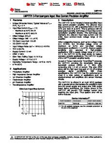
IV. DTC of the Five-Phase Induction Motor
flux λ s along a predetermined path. The objective of DTC of the five-phase induction motor is to maintain the stator flux and torque within the limits of flux and torque hysteresis bands by proper selection of the 32 stator space voltage vectors during each sampling period as shown in Fig.7. The voltage vectors are selected according to the errors of stator flux and torque ( ∆λ = λ∗ − λe and ∆T = T ∗ − Te ). The 32 voltage vectors are divided into three groups according to their amplitudes, which is 1 : 1.618 : 1.618 2 from the smallest one to the largest one respectively. The larger the amplitude of voltage vector is, the higher its influence is on the flux λs and torque Te .
Furthermore, the relationship between the torque of five-phase induction motor and space voltage vector Vs can be induced as: dT (9) Lσ e ≈ P(λs × Vs ) − RmTe − P 2ω r (| λs |2 ) ; dt where, d p = ; Tr = Lr ; dt Rr
V28 V12
V13 V4
V15
V10
V29
V20
V32 V0
V26 V9
V22
V6
V21
V5 V11
V2
Sector1
V25 V16
V27
V18
V17 V1
V23 V7 V19 V3
Fig.7 Space voltage vectors of five-phase inverter.
The space voltage vector V s can be expressed as follow: 2π
4π
4π
2π
−j −j j j 2 E d [S a + S b e 5 + S c e 5 + S d e 5 + S e e 5 ] ; (6) 5 where, E d is the DC link voltage; and S a , S b , S c , S d , S e are the
Vs =
five-phase inverter switching functions, which can take either 1 or 0 value based on the state of the upper or lower switch. If the upper switch is ‘on” then the switching function assumes a value of ‘1’, else ‘0’. According to the basic equations of induction motor [10][11], the stator flux λs can be written as:
λ s = ∫ (V s − I s R s ) dt ; t
Ls Lr − L2m ; Lm
Rm =
Rs Lr + Rr Ls . Lm
When the stator flux λ s maintains constant, the proper selection of the space voltage vectors can increase or decrease the torque quickly. Therefore, by employing different space voltage vectors V s , both the stator flux and
V24 V8 V30 V14
Lσ =
(7)
0
Since stator resistance Rs is relatively small, the voltage drop I s Rs might be neglected. The discrete time representation of the above equation is: (8) λs(n) = λs(n−1) +Vs *T ; where T is the system sampling period. It is clear that stator flux directly depends on the space voltage vector Vs and the sampling period. Therefore, by selecting the thirty-two voltage vectors Vs properly it is
torque of the five-phase induction motor can be controlled simultaneously. Due to the number of the space voltage vectors of the five-phase induction motor, it is almost impossible to adopt a table-seeking method to complete the selection process for each sampling period in the simulation and the real-time control program. Therefore, a corresponding algorithm instead of the conventional table-seeking method is developed to select voltage vectors, which greatly reduces the executing time of the real-time control program and shortens the sampling period correspondingly. This further reduces the flux and torque pulsation of the five-phase induction motor. Fig. 8 is the block diagram representation of the DTC control strategy for five-phase induction motor. The system consists of the inner torque loop, the stator flux loop and the outer speed loop.
REC
Torque Comparator ∗
Speed PI Controller
T
*
Voltage Vector Table
T
ω Given Flux
λ
∗
λ
Switch Status
5-phase INV
Flux Comparator Flux Position
Torque Observer
5/2 Transform
Flux Observer
5-phase IM Speed Encoder
Fig.8 Block diagram of DTC for 5-phase induction motor drive.
Whenever a speed command ω r ∗ is given, the system automatically compares it with the motor actual speed ω r . Since the error of speed directly effects torque, the output of speed PI controller is used as the torque reference value Te∗ to make the necessary torque adjustment to make the motor speed ω r follow the given value ω r ∗ . At the same time, the DTC system samples in real time the five-phase stator currents ias , ibs , ics , ids , ies and DC link voltage Ed , which are used to observe the stator flux λs and torque Te . These values are compared with the reference values of the stator flux λs ∗ and torque Te∗ . As a result, an optimal voltage vector table is generated, and then sends out the switch gating signals to control the five-phase motor drive.
V. Experiment Results According to the control strategies of RFOC and DTC of the five-phase induction motor as described above, Experiments have been carried out for a 7.5hp five-phase induction motor using TMS320C32 DSP. Fig.9 illustrates the experimental results of FOC of the five-phase induction with the combined fundamental and third harmonic currents. The waveforms shown are the stator current ias , the stator voltage v ab , the stator flux linkage λs and the motor peed
ω r respectively. Consistent with the theoretical analysis, the stator current is a nearly square waveform as desired. The stator flux linkage, which is similar to the air-gap flux, is also close to the square waveform. From the motor actual speed, RFOC system is very stable during the steady state.
Fig.9 From top to bottom: 1. A phase current ia ; 2. Line voltage between A-phase and B-phase 3. Stator flux linkage
v ab ;
λs ;4. Rotor peed ω r .
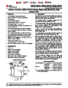
Fig. 10 presents the experimental results of DTC for five-phase induction motor for the stator current ias and speed ω r during start-up. It appears that the stator current and speed regulations have a swift response, which quickly achieve the steady state. The waveforms shown in Fig.11 are the stator current ias , the stator flux linkage λqs and the torque Te respectively. The stator current
ias and flux λqs in
this figure are practically sinusoidal waveforms with very low pulsations. The steady state torque is also smooth. These are due to the high processing speed of TMS320C32 DSP while enabling a DTC system with a very high precision. The shorter the sampling period is, the smaller the pulsations of the stator current, flux and torque will be.
500ms/div-t 2.0A/div-Ia
0.0000
200rpm/div-w
Fig. 10 Dynamic response of the stator current and speed
of the five-phase induction motor.
8ms/div-t 2.0A/div
References
0.0000 0.5Wb/div-Fluxq 5Nm/div-Te
Fig. 11 Experimental results of DTC of five-phase induction motor, from top to bottom: (a) Stator current (A); (b) Stator q-axis flux (Wb); (c) Developed torque under no load (Nm).
VI. Conclusions This paper describes the implementation of RFOC and DTC for the five-phase induction motor using a 32-bit floating-point TMS320C32 DSP. Hardware architectures of the system and control strategies of RFOC and DTC are mainly presented. Experimental results show that a very good dynamic and steady state performance can be obtained with the combination of RFOC and DTC of the five-phase induction motor and TMS320C32 DSP, which further demonstrates that the floating-point DSP has great practical prospect in motor drives.
Acknowledgment This paper is based in part upon work supported by the Office of Naval Research under Grant No. N00014-98-10717.
Appendix The parameters of five-phase induction motor used in the simulation and experiment are as follows: Power 7.5hp Phase voltage 230V Poles 4 Stator resistance 0.22Ω Rotor resistance 0.16Ω Stator leakage inductance 4.76mH Rotor leakage inductance 1.7mH Mutual inductance 151.5mH
Mechanical motion inertia
0.04Kg ⋅ m2
[1] B.K.Bose, “High Performance Control and Estimation in AC Drives”, Industrial Electronics Control and Instrumentation, 23rd International Conference on Volume: 2 , 1997 , pp.377 -385 [2] I. Takahashi, and Y. Ohmori, “ High-performance direct torque control of an induction motor ”, IEEE Trans. Ind. Appl. Vol. 25, No.2, March/April 1989, pp257-264. [3] Peter Vas, “Sensorless Vector Control and Direct Torque Control”, Oxford University Press, 1998. [4] W.Leonhard, “Field-orientation for controlling AC machines-principle and application”, Power Electronics and Variable-Speed Drives, Third International Conference on 1988, Page(s): 277-282 [5] H.A. Toliyat, T.A. Lipo, and J.C. White, "Analysis of a Concentrated Winding Induction Machine for Adjustable Speed Drive Applicationspart II (Motor Design and Performance)," IEEE Transaction on Energy Conversion, vol. 6, No. 4, Dec. 1991, pp. 685-692. [6] H.A. Toliyat, and T.A. Lipo, "Analysis of Concentrated Winding Induction Machines for Adjustable Speed Drive ApplicationsExperimental Results," IEEE Transactions on Energy Conversion, Vol. 9, No. 4, Dec. 1994, pp. 695-700. [7] H.A. Toliyat, L. Xue, and T.A. Lipo, "A Five Phase Reluctance Motor with High Specific Torque," IEEE Transaction on Industry Applications, vol. 28, No. 3, May/June 1992, pp. 659-667. [8] I. Takahashi, and T. Noguchi, " A New Quick Response and High Efficiency Control Strategy of an Induction Motor", IEEE Trans. Ind. Appl. Vol. IA-22, No.5, Sept./Oct. 1986, pp820-827. [9] M. Depenbrock, "Direct self-control (DSC) of inverter-fed IM", IEEE Trans. on PE-3, No. 4, Oct. 1988, pp. 420-429. [10] H.A. Toliyat, and Huangsheng Xu, “A Novel Direct Torque Control (DTC) Method for Five-Phase Induction Machines,” Proceedings of the 2000 Applied Power Electronics Conference, APEC’00, Fifteenth Annual IEEE, Vol. 1, pp. 162 -168 [11] H.A. Toliyat, and H. Xu, “DSP-Based Direct Torque Control (DTC) for Five-Phase Induction Machines,” International Power Electronics Conference, IPEC’00, Tokyo, Japan, pp.1195-1200 [12] User’s Guide of TMS320C3x Floating-Point DSP, TI Inc. 1997 [13] Technical Reference Manual, PC/C32 Board. Document No. 50000278, Spectrum Corp. 1996 [14] Manual, PC/16IO8 Multi-Channel I/O Board. Document No. 50000211, Spectrum Corp. 1996 [15] H.A. Toliyat, M.M. Rahimian, and T.A. Lipo, "dq Modeling of Five Phase Synchronous Reluctance Machines Including Third Harmonic of Air-Gap MMF," Proceedings of the IEEE-IAS Annual Meeting Conference, October 1991, pp. 231-237. [16] H.A. Toliyat, S. Waikar, T.A. Lipo, "Analysis and Simulation of Five Phase Synchronous Reluctance Machines Including Third Harmonic of Air-Gap MMF," IEEE Transactions on the Industry Applications, Vol. 34, No. 2, March/April 1998, pp. 332-339. [17] Peter Vas, Vector Control of AC Machines, Clarendon Press.Oxford, 1990 [18] Jung-Ik Ha, and Seung-Ki Sul, “Sensorless Field-Orientation Control of an Induction Machines by High-Frequency Signal Injection”, IEEE Trans. on Indus. App., Vol.35 No.1 Jan./Feb. 1999. pp. 45-51.