IMPLEMENTING SCRUM USING BUSINESS PROCESS MANAGEMENT AND PATTERN ANALYSIS METHODOLOGIES Ron S. Kenett KPA Ltd., Raanana, Israel University of Torino, Turin, Italy Center for Risk Engineering, NYU, New York, USA
[email protected]
Abstract The National Institute of Standards and Technology in the US has estimated that software defects and problems annually cost 59.5 billions the U.S. economy (http://www.abeacha.com/NIST_press_release_bugs_cost.htm). The study is only one of many that demonstrate the need for significant improvements in software development processes and practices. US Federal agencies, that depend on IT to support their missions and spent at least $76 billion on IT in fiscal year 2011, experienced numerous examples of lengthy IT projects that incurred cost overruns and schedule delays while contributing little to mission-related outcomes (www.gao.gov/products/GAO-12-681). To reduce the risk of such problems, the US Office of Management and Budget recommended deploying an agile software delivery, which calls for producing software in small, short increments (GAO, 2012). Consistent with this recommendation, this paper is about the application of Business Process Management to the improvement of software and system development through SCRUM or agile techniques. It focuses on how organizational behavior and process management techniques can be integrated with knowledge management approaches to deploy agile development. The context of this work is a global company developing software solutions for service operators such as cellular phone operators. For a related paper with a comprehensive overview of agile methods in project management see Stare (2013). Through this comprehensive case study we demonstrate how such an integration can be achieved. SCRUM is a paradigm shift in many organizations in that it results in a new balance between focus on results and focus on processes. In order to describe this new paradigm of business processes this work refers to Enterprise Knowledge Development (EKD), a comprehensive approach to map and document organizational patterns. In that context, the paper emphasizes the concept of patterns, reviews the main elements of SCRUM and shows how combining SCRUM and EKD provides organizations with a comprehensive framework for managing and improving software and system development. Keywords: SCRUM, agile development, business process management, organizational patterns, enterprise knowledge development (EKD)
1. INTRODUCTION In the past, service providers focused on achieving top-line growth through customer acquisition. Although this is still a top priority, service providers are currently facing new challenges, such as service commoditization, market saturation and new competition. Customers currently have more choices than ever before and, in their relationships with service providers, customers demand simplic-
ity, convenience, value and new products. In addition, telecom, media, and software companies are now competing on each other's traditional turf, with cable companies offering phone service, Telco providing satellite TV, and software developers tying it all together. If telecommunications giants are to thrive in this highly competitive landscape, they will need to cut operating costs dramatically while learning to be brisk innovators of new products and services. Large carriers with extensive legacy systems tend to reduce their overall list of suppliers. They
Dynamic Relationships Management Journal, November 2013
29
Ron S. Kenett: Implementing SCRUM using Business Process Management and Pattern Analysis Methodologies
should select one strategic best-in-class supplier that addresses their requirements and business goals in each of their key solutions areas. Service providers are required to continuously enhance their products and services helping to ensure maximum operational efficiency is achieved through alignment, innovation through agility and time to market, and customer loyalty through the intentional customer experience. Information systems have a major influence on the agility of a company. They can inhibit or enhance it. Agility means the time it takes to adapt to environmental shifts quickly by changing products, systems and business processes. The agility of company information systems cannot be achieved by accelerating product/system development using traditional development processes and architecture. Agility must be built into the core development processes, roles and architecture taking into accounts the complexity of large global development organization that need to support very large service providers. ABC Inc. is a typical large supplier of software and services solutions to services providers worldwide. The company offers customer relationship management, order management, service fulfillment, mediation, and content revenue management products, collectively known as Integrated Customer Management (ICM) enabling systems. These ICM Enabling Systems support various lines of business, including wireline, wireless, cable, and satellite, as well as a range of communications services, such as voice, video, data, Internet protocol, broadband, content, electronic, and mobile commerce. ABC Inc. also supports companies that offer bundled or convergent service packages. In addition, it provides directory sales and publishing systems for publishers of both traditional printed yellow page and white page directories, and electronic Internet directories. In addition, the company's information technology services comprise consulting, business strategy, system implementation, training, integration, and modification. Further, ABC Inc. provides managed services that include system modernization and consolidation, operation of data centers, ongoing support, maintenance services, system modification, provision of rating and billing services, and communications facility management services. Its customers include communi-
30
cations providers, and network operators and service providers. The company was founded in 1982. The company's workforce of more than 16,000 professionals are located in more than 50 countries, with development and support centers in Brazil, Canada, China, Cyprus, India, Ireland, Israel and the USA. ICM requires improved software development capabilities. This paper is about the application of new software development paradigms in large global organizations such as ABC Inc. Specifically; this work focuses on the application of Business Process Management to the improvement of software and system development through SCRUM. Implementing ICM using SCRUM or any other agile approach in large multisite organizations with highly demanding customers, is a significant challenge. Governance in such a context where knowledge management is critical and dissemination of best practices across teams and cultures is required, poses problems of capturing process patterns, storing this knowledge and ensuring knowledge reuse needs to occur. This paper presents a framework for addressing this challenge in a practical way. The main elements of SCRUM are reviewed in the next section that also shows how combining SCRUM and EKD (Enterprise Knowledge Development), a Business Process Management methodology, provides organizations with a comprehensive framework for managing and improving software and system development.
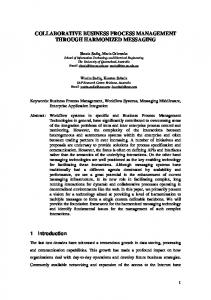
2. AGILE SOFTWARE DEVELOPMENT 2.1 Background Many software projects do not achieve their goal with respect to time to market, budget, quality and/or customers expectations. The National Institute of Standards and Technology in the US has estimated that software defects and problems annually cost 59.5 billions the U.S. economy. The study is only one of many that demonstrate the need for significant improvements in software development processes and practices (http://www.v3. co.uk/v3-uk/news/1973196/software-bugs-cost-billions). See also GAO (2012). The main root-cause for this was found not in the technology arena but in the development process methodology (see Figure 1 based on data from a research conducted in 2003 by Forrester Research).
Dynamic Relationships Management Journal, November 2013
Figure 1: Corporate Executives’ Reasons For Project Failures
One possible response to this phenomenon is to make developing methodologies more disciplined and predictive, i.e., more planning, greater attention on analysis of requirements, formal sign-off, detailed and documented design before coding, strict change control etc... This approach is known as the "waterfall process" (Kenett & Baker, 1999). Under this approach the organization gets better control but project success rates does not necessarily improve. Many organizations have found that, by this approach: • Methodologies simply prove bureaucratic and slow to deliver. • It is hard for the business to completely conceptualise all requirements in one pass. • It is even harder to capture all the requirements in a document in a completely detailed and unambiguous form, The customer does not understand UML and specs, that's lead to free interpretation of the requirements by the different players through the development downstream (e.g. system analysts, designers, developers, testers). • Businesses constantly change - requirements and business priorities constantly change, the longer the project the greater the risk. If change is successfully suppressed, the business gets software they can’t use. • Its hard to completely design a system in one exercise and not of great value if the requirements change anyway.
• Developers do not know how to estimate the impact of complex requirements. For more on problems in software development processes see April et al., 2005, BerntssonSvensson & Aurum, 2006 and Kenett & Baker, 2010. An alternative to the waterfall process, that encourages software development involving a high degree of innovation, is a software development paradigm labeled the "agile process" (http://en.wikipedia.org/ wiki/Agile_software_development). The next subsection provides an introduction to the agile process. 2.2 The Agile Process One of the main ideas behind agile methodologies is that evolutionary processes that seek to move by a large number of small steps, on schedule based cycles (30-90 days), each of which deliver some benefits that are stable and workable solution is more effective. A common rule of thumb is that 20% of the features of a system delivers 80% of the benefit, so earlier more frequent releases can bring significant gains. A particular important observation about agile processes is that they seek to shorten or eliminate feedback loops. For example, bringing empowered users into contact with the development team can remove much longer cycles of trying to describe what is needed, developing it and trying out the product (Takeuchi & Nonaka, 1986, 1995).
Dynamic Relationships Management Journal, November 2013
31
Ron S. Kenett: Implementing SCRUM using Business Process Management and Pattern Analysis Methodologies
Similar observations can be made about other agile practices such as establishing a joint cross discipline team that accountable as a team to deliver the feature. The communication is mostly face to face, with minimal unnecessary documentation (versus the waterfall model were the main mean of communication between the disciplines are through documentation that leads to the need of interpretations). Also other agile practices such as automatic unit testing, pair programming (versus peer reviews), daily stand-up meetings for planning, automated build and regression testing derived from the notion that getting better feedback sooner improves both quality and control. Finally priority-driven planning is an essential feature of most agile methods. Managing requirements individually, rather than as a composite document, allows the high benefit, low cost features to be rolled out to users sooner. Also fixing timescales for deliveries rather than fixing the required features and allowing timescales to slip, is a far more effective means of ensuring continuous enhancement of business performance.
is sufficiently generic to apply across the organization whilst providing detailed guidance. This framework in itself has the power to improve agility through helping programmers to structure their deliveries into shorter cycles while also steering them towards a more iterative and collaborative approach (Cohn & Ford, 2003). The next section describes the basic elements of the agile process. 2.3 SCRUM One of the most common agile methodologies is SCRUM that mainly focus on the way agile project should be managed. It was first described in 1986 by Takeuchi and Nonaka. SCRUM is not an acronym, name taken from the sport of Rugby, where everyone in the team pack acts together to move the ball down the field. Analogy to development is the team works together to successfully develop quality software. In particular: “SCRUM” refers to the entire team banding together for a single aim: getting the ball!
In systems development, an evolutionary approach requires investment – particularly in test-driven design, continuous integration and comprehensive automated build facilities from a configuration management system. Such investment is nearly always worthwhile since it can eliminate a separate integration and test phase and allow early release of useful functionality. The traditional Quality Gates are not applicable to the new agile process since now activities are not divided into phases, but rather focused around implementation of individual features or stories. To replace Quality Gates the new agile framework proposes a set of repeating checkpoints. Some checkpoints repeat only once in iteration, for example the checkpoint that marks the end of the iteration planning, or the iteration review at the end. Other checkpoints are associated with individual requirements or features, such as the checkpoint that marks completion of a feature. While these checkpoints occur much more frequently than Quality Gates, and in an agile process must be much lighter weight in terms of ceremony (For more on agile development see Schwaber & Beedle, 2001; Kenett & Baker, 2010).
• A SCRUM Master mentors and manages the self organizing and self accountable teams that are responsible for delivery of successful outcomes at each sprint.
For agile methods to scale up, the most important thing is to establish a suitable framework that
• A daily standup meeting is a primary communication method.
32
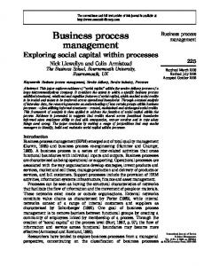
2.3.1 The SCRUM Process Figure 2 presents conceptually the SCRUM process (adapted from Kenett and Baker, 2010). Key SCRUM practices include: • Focus on schedule based cadence, sprints are iterations of fixed 30 days duration. • Work within a sprint is fixed. Once the scope of a Sprint is committed, no additional functionality can be added except by the development team. • All work to be done is characterized as product backlog which includes requirements to be delivered, defect workload, as well as infrastructure and design activities. • The product Backlog is the basis for the Sprint backlog as defined by the sprint team and the product owner. The team decides what it can develop.
Dynamic Relationships Management Journal, November 2013
• A heavy focus on time boxing. Sprints, standup meetings, release review meetings and the like are all completed in prescribed times. • SCRUM also allows requirements, architecture and design to emerge over the course of the project. SCRUM lifecycle phases are Planning, Staging, Development, and Release. There are typically a small number of development sprints to reach a release. Later sprints focus more on system level quality and performance as well as documentation and other activities necessary to support a deployed product. Typical SCRUM guidance calls for fixed 30 day sprints, with approximately three sprints per release, thus supporting incremental market releases on a 90 day timeframe (Schwaber & Beedle, 2001). 2.3.2 Roles in SCRUM Agile development is carried out by individuals with specific roles and responsibilities. These are described below:
• SCRUM Master Main focus is to safeguard the process, removing the barriers between development and the customer, enable close cooperation between roles and functions across the organization, facilitating creativity and empowerment. Improving the productivity of the development team in any way possible; and, Improving the engineering practices and tools so each increment of functionality is potentially shippable. • SCRUM Team This is a cross-functional group of people with all the different skills that are needed to turn requirements into something that is an increment of potentially shippable functionality. The SCRUM Team responsible for the project, committed to deliver. Has the right to do everything within the boundaries of the project guidelines to reach the iteration goal. The team consists typically from 510 people, Cross-functional team (QA, Programmers, Designers, etc.). Members should be full-time as possible. Teams
Figure 2: The SCRUM process
Dynamic Relationships Management Journal, November 2013
33
Ron S. Kenett: Implementing SCRUM using Business Process Management and Pattern Analysis Methodologies
are self-organizing, ideally, no titles but rarely a possibility. Membership can change only between sprints. • Product Owner The 'Product Owner' is responsible for the financial success of the project. So this is the person who is investing or representing everyone's interest in the project and serves as the ultimate arbiter on any requirements issues and accepts or rejects work results. The product owner defines the features of the product, decides on release date and content, prioritizes features according to market value, can change features and priority every Sprint, this requires high bandwidth communication and transparency into the team’s progress. • Management Management is in charge of final decision making, along with the charters, standards and conventions to be followed by the project. Management also participates in setting the goals and requirements. 2.3.3 Meetings/Activities in SCRUM Work in an agile development environment requires a high degree of synchronization. To achieve this one carries out a series of well-orchestrated and actively managed meetings and activities. These are described below. • Pre-game – High level design and Architecture In the architecture phase the high level design of the system including the architecture is planned based on the current items in the Product backlog. In case of enhancement to an existing system the changes needed for implementing the Backlog items are identified along the problems they may cause. A design review meeting is held to go over the proposals for the solution and decisions are made. In addition, preliminary plans for the contents of releases are prepared. • Pre-Game - Release Planning The Product Backlog lists all the functionality that the product or solution could have in it. If all of this functionality is built before a release to production it may waste the opportunity that SCRUM provides for seeing an early return on investment
34
and useful production feedback. For these reasons it is common practice to divide the Product Backlog into "Releases" or collections of useful system capability that make sense when put into production. • Sprint Planning Usually every sprint has a goal or main theme that express the Product Owner’s motivation for this sprint, embodied as specific measurable exit criteria. Each Sprint must include some business functionality. The sprint planning session consist of 2 segments (usually around 4 hours each). Segment 1 - The Product Owner selects the ideal backlog for the coming Sprint and communicates its meaning and importance to the team. Segment 2 - Team decides what they can commit to delivering in the Sprint. The Product Owner answers questions but does not direct the team’s choices. The Team decides how to turn the selected requirements into an increment of potentially shippable product functionality. The team self-organizes around how they’ll meet the Sprint Goal, The Team devises its own tasks and figures out who will do them. The outcome is the Sprint Backlog. • Spike A spike is an experiment that allows developers to learn just enough about something unknown in a user story, e.g. a new technology, to be able to estimate that user story. A spike must be timeboxed. This defines the maximum time that will be spent learning and fixes the estimate for the spike. • Daily SCRUM A short status meeting that is time-boxed to 15 minutes and is held daily by each Team. During the meeting the Team members synchronize their work and progress and report any impediments to the SCRUMMaster. • Sprint Review The Sprint Review provides an inspection of project progress at the end of every Sprint. The team presents the product increment that it has been able to build. Management, customers, users, and the Product Owner assess the product increment. Evaluation possible consequences: Restoring unfinished functionality to the Product Backlog and
Dynamic Relationships Management Journal, November 2013
prioritizing it. Removing functionality from the Product Backlog that the team unexpectedly completed. Working with the SCRUMMaster to reformulate the team. Reprioritizing the Product Backlog to take advantage of opportunities that the demonstrated functionality presents. Ask for a release Sprint to implement the demonstrated functionality, alone or with increments from previous Sprints. Choosing not to proceed further with the project and not authorizing another Sprint. Requesting that the project progress be sped up by authorizing additional teams to work on the Product Backlog. • Sprint Retrospective This is a meeting facilitated by the SCRUMMaster at which the Team discusses the just concluded Sprint and determines what went well and what could be changed that might make the next Sprint more productive. While the Sprint Review looks at "What" the team are building whereas the Retrospective looks at "How" they are building. • Post-Game – Release sprint (integration, system packaging) When the Product Owner and Stakeholders identify that there is sufficient functionality in the system to provide immediate business value they may choose to put this into production. Typically, a "Release Sprint" will follow that contains all the necessary Sprint Backlog tasks to put the system into production. These tasks shouldn't contain additional functionality but they may include: Full end-2-end system test, integration, performance and regression test if necessary. Finishing required documentation, Deploying the code to the Production Environment, production data population, setting up management and operational systems and processes, training and handover for support staff and Cutover and fallback planning. 2.3.4 SCRUM Artifacts Artifacts are concrete deliverables that are produced and maintained during software development. We list here the five most important artifacts associated with agile development. 1. Product Backlog A product backlog is a prioritised list of project requirements with estimated times to turn
2.
3.
4.
5.
them into completed product functionality. Estimates are in days and are more precise the higher the item is in the Product Backlog priority. Priority should be assigned based on the items of most value to the business or that offer the earliest Return on Investment. This list should evolve, changing as the business conditions or technology changes. Sprint Backlog The Sprint backlog is a list of tasks that defines a Team's work for a Sprint. The list emerges during Sprint planning. The tasks on the Sprint backlog are what the Team has defined as being required to turn committed Product Backlog items into system functionality. Each task identifies who is responsible for doing the work and the estimated amount of work remaining on the task on any given day during the Sprint. Impediment list Anything around a SCRUM project that impedes its productivity and quality is an impediment. It is the responsibility of the SCRUMMaster to remove any impediment that is stopping the team from producing production quality code. The impediment list is simply a set of tasks that the SCRUMMaster uses to track the impediments that need to be solved. Task List Tasks to turn product backlog into working product functionality. Tasks are estimated in hours, usually 1-16. Tasks with more than 16 hours are broken down later. Team's member sign up for tasks, Team members shouldn’t sign up for work prematurely (until actually starting that task). Estimated work remaining is updated daily, any team member can add, delete or change the Sprint Backlog. Work for the Sprint emerges, if the team believes that this become too much, they can meet again with the Product Owner. Product Burndown Chart The Product Burndown chart gives an indication of how quickly the team are "Burning" through the work and delivering Product Backlog requirements. It is a useful tool for helping to plan when to release or when to remove requirements from a release if progress is not rapid enough.
Dynamic Relationships Management Journal, November 2013
35
Ron S. Kenett: Implementing SCRUM using Business Process Management and Pattern Analysis Methodologies
2.3.5 Scaling SCRUM in big projects The primary way of scaling SCRUM to work with large teams is to coordinate a "SCRUM of SCRUMs". With this approach each SCRUM team proceeds as normal but each team also contributes one person who attends SCRUM of SCRUM meetings to coordinate the work of multiple SCRUM teams. These meetings are analogous to the Daily SCRUM Meeting, but do not necessarily happen every day. In many organizations, having a SCRUM of SCRUMs meeting two or three times a week is sufficient. Implementing SCRUM is basically an organizational change. Implementing such a change in a large organization is a complex task that requires a filed tested methodology. The next section describes, EKD, a Business Process Methodology that has been used to transform major organizations such as electricity supply companies (Rolland et al., 1998, 1999). In particular, it describes the concept of "patterns" as an approach to capture knowledge and allow for organizational learning and re-use. The following section shows how to implement SCRUM in the context of a large organization using EKD. The final section concludes with some discussion and directions for future research.
3. BUSINESS PROCESS MANAGEMENT 3.1 An Introduction to Enterprise Knowledge Development (EKD) Enterprise Knowledge Development (EKD) was developed in the FP4 ELEKTRA project supported by the European Commission as a Business Process Management methodology for large organizations (http://crinfo.univ-paris1.fr/PROJETS/elektra.html). It provides a controlled way of analysing and documenting an enterprise, its objectives and support systems. The approach represents an integrated set of techniques and associated tools for the purpose of dealing with situations of mapping business processes and re-engineering of information systems. At the centre of the approach is the development of enterprise knowledge models pertaining to the situations being examined (Rolland et al., 1998, 1999). The definition of such models is carried out using appropriate modelling techniques and tools. The process followed in developing these models,
36
and subsequently using them, is the subject matter of the guidance component. During the process of developing these models, the participant parties engage in tasks that involve deliberation and reasoning. The purpose is to provide a clear, unambiguous picture of how enterprise processes function currently in an "as is" model or in a modified "should be" model. The EKD approach considers the concept of an ‘enterprise process’ as a composite of four key enterprise components: (a) the roles that are played by enterprise actors in order to meet the process goals; (b) the activities involved in each role; (c) the objects that are involved together with their evolution from creation to extinction (within the context of the enterprise process); and (d) the rules that determine the process components. In other words, an enterprise process may transcend any functional divisions and presents a dynamic view of an enterprise system. Systems are composed of interfacing or interdependent parts that work together to perform a useful function. System parts can be any combination of things, including people, information, software, equipment, products, or raw material. In effect, operational models should describe what a system does, what controls it, what it works on, what it uses to perform its functions, and what it produces. Actor-role modelling is about representing the organisational and behavioural aspects of an enterprise. This aspect of modelling is concerned with the way that a business process is performed through the involvement of enterprise actors in discharging their responsibilities through their role in a process and the interaction of their role with other roles which collectively bring about the realisation of the business processes. Through enterprise actor-role modelling, EKD encourages the identification of the key operational components which can be measured (activity duration, actor skills, resource costing etc.). Such measurable components can then be subjected to ‘what-if’ scenaria in order to evaluate alternative designs for the operation of an enterprise. A high-level view of the association between actors and their different roles is supported through the actor-role diagram. The actor-role diagram depicts the actors of the enterprise and the roles that they play. For each role involved in the model, infor-
Dynamic Relationships Management Journal, November 2013
mation is given about the responsibilities that are assigned to the role in terms of the activities that the role carries out and the enterprise resources that the role requires. The diagram also presents the dependencies that exist between the roles. An additional element represented in this view is the goal (or goals) that the role must satisfy. The actor-role diagram can be used to get a ‘first-cut’ view of the organisational aspects regarding the responsibilities of individuals or groups in their involvement in the operation of a business process. A detailed view of the activities in which a role is engaged is supported by the role-activity diagram. This diagram describes in detail how the role performs each of its responsibilities, in terms of activities undertaken and is based on the notation of the RAD (role activity diagram) approach . An important point to note is the distinction between the actor, i.e. the physical enterprise entity, and the role, a notion which expresses the responsibility of performing the various activities within the enterprise. Roles are assigned to actors and summarise a set of skills or capabilities necessary to fulfil a task or activity. A role can be acted by a person or a group. A role can be acted by person X on one day and person Y on another day. The role is separate from the actors that play the role. For example, a managing director may play multiple roles such as ‘setting the budget’ ‘approving expenses’, etc. A role is a collection of components of either operational or structural nature expressing responsibilities. Operational components represent the activities that the role has to perform. Structural components represent resource objects that are required by one or more activities being carried out by the role. These may be physical or informational. The role can thus comprise behavioural aspects of the organisational life as well as hierarchical and social aspects. The notation for a role and its goals is shown in Figure 3.
3.2 EKD Actor and Role Components 3.2.1 The Actor It is essential to distinguish between the role and the carrier of the role, i.e. the actor who at a specific moment might play the role. The role exists independently of what organisational entity is chosen to play it; this particular choice can be changed over time, as particular actors may change in carrying the responsibilities of a role. A role should therefore be considered as a stable and accountable concept, one that summarises a set of responsibilities and the activities that are performed in order to fulfil these responsibilities. An actor is the physical entity that personifies an instance of the role at any given moment; an actor may play several roles at the same time. In that sense, while the selection of roles and their responsibilities can be considered as a design choice, the selection of actors for playing individual roles can be considered as an implementation strategy. In EKD, the notation for the actor concept is the actor box (Figure 4). Figure 4: The actor box
3.2.2 The Actor-Role Relationship The relationship between a role and the actor that, at a particular time, incarnates this role is represented by the plays relationship which is shown as an arrow (Figure 5). The arrow connects an actor box with a role box and illustrates that the actor plays the particular role. Figure 5: The actor-plays-role arrow
Figure 3: The role box and its goals 3.2.3 The Role-Role Relationship Roles are often dependent upon other roles in order to perform the duties assigned to them. There are two parties involved in the dependency: the requester role, i.e. the one that needs something in order to fulfil its responsibilities, and the provider
Dynamic Relationships Management Journal, November 2013
37
Ron S. Kenett: Implementing SCRUM using Business Process Management and Pattern Analysis Methodologies
role, i.e. the one that can provide the missing component. This relation can be of various types: Authorisation dependency: this denotes hierarchical dependencies that can exist between roles; the provider role gives authorisation to the requester role. For instance, in order to for changes to some customer accounting data to be performed, an authorisation of the responsible manager must be given. Goal dependency: this relationship reflects the fact that the achievement of a goal that the role brings about is dependent on the achievement of a goal of another role. For instance, the goal of the customer service provision to satisfy customers promptly depends on satisfaction of the goal on immediate availability of programmers expressed by the human resource FTE numbers. Generation of artifacts or deliverables is also considered a goal. Coordination dependency: this type of dependency expresses the need for one role to wait for completion of another role’s responsibilities before it can complete its own. For example, in order for the material provision service to purchase material, an appropriate invoice must first be prepared by the accounting service.
3.2.4 Using the Notation The role box consists of the name of the role and its components, which are drawn within its boundary. A sample role box and the actor that plays the role is presented in Figure 7. Figure 7: A sample of actor-role relationship
The dependency relations, is shown by drawing a dependency arrow between the two role boxes. A sample actor-role diagram comprising two roles, their respective actors and a coordination dependency is illustrated in Figure 8. Figure 8: A sample actor role diagram
Resource dependency: this illustrates the need for one role to use a resource that can be provided by another role. For instance, the construction service requires material that is under the supervision of the warehousing service. The dependency relationships are represented by the dependency arrow, as depicted in Figure 6. The dependency arrow is accompanied by the initial of the dependency type and superscripted by any additional details on the dependency. The initials of the dependency types are A for authorisation dependency, R for resource dependency and C for activity coordination dependency [the “ARC” dependency]. The dependency arrow is directed from the provider role towards the requester role. Figure 6: The dependency arrow
3.2.5 Guidelines for the Actor-Role Diagram 1. An actor cannot exist without playing any role, i.e. at any moment every actor within the organisation should be assigned at least one role. 2. If more than one dependencies are identified between roles, multiple arrows are drawn, each annotated by the respective dependency type and details. 3.2.6 Examples of Actor-Role Diagrams A number of examples in this section demonstrate the concepts (and the use of the notation) for actor-role modelling.
38
Dynamic Relationships Management Journal, November 2013
The actor-role diagram of Figure 9 represents a situation of two actors each playing a different role with different goals and the dependency of the “service customer” role on “supervise local support” role. The former requires the latter in order to perform certain activities. This kind of dependency shows the structural relationship between the two roles as being one of authorisation (indicated by the “A” on the dependency line).
Activity Refinement Apart from sequential execution of activities, one can also have parallel execution of more than one activities. Moreover, selection can be made between two or more activities , according to whether a condition is satisfied or not. These controls over activities are called part refinement and case refinement, respectively, and they are illustrated in Figure 11 Part refinement and case refinement.
Figure 9: An example actor-role diagram with “authorisation” dependencies
In part refinement two or more parallel activity sequences are initiated with circles, while in case refinement the alternative activity sequences are initiated with triangles, which also indicate the value of the criterion that determines which of the alternatives is executed. With respect to 11, in the left part activities A2 and A3 are executed in parallel after activity A1; in the right part one of the two activities is selected according to the answer to the question posed. Figure 11: Part refinement and case refinement
3.3 EKD Role-Activity Diagram 3.3.1 Basic Concepts and Notation The Role The concept of a role is also used in the role-activity diagram. In this case, however, it is used to group together the details of the activities being carried out within the enterprise, including information on their order of execution and their interdependencies. Activity Sequence The activities that a role performs are represented as sequences of nodes. Nodes are drawn as black squares, which are connected with a straight vertical line. These primitives are illustrated in Figure 10.
Role interaction At some point during an activity sequence a role may need to interact with another role. This means that both roles will be involved in activities that make their respective actors communicate in various ways. The notation for this interaction is represented as a horizontal line connecting the two activities across the boundaries of the roles, as shown in Figure 12. Figure 12: Role interaction
Figure 10: Activity sequence components
Dynamic Relationships Management Journal, November 2013
39
Ron S. Kenett: Implementing SCRUM using Business Process Management and Pattern Analysis Methodologies
The level of detail of the interaction is not specified, nor is the duration of the interaction. Depending on the case, an interaction can be decomposed into smaller, more detailed activities and interactions, or it can be represented as a single interaction. This choice, however, is left to the model designer and is related to the importance of the specific interaction in the overall model. 3.3.2 Using the notation The activities of which a role consists are refined in this level. The role box now contains a sequence of activities, possibly refined according to one of the refinement schemes previously presented, as illustrated in Figure 13. Figure 13: A role-activity diagram
3.3.3 Guidelines for the Role-Activity Diagram Dependencies identified at the actor-role level model are represented as interactions at the role-activity level; indeed, interdependencies between roles are translated into specific activities at this level, which constitute the interface between the roles. 3.4 An Overview of Patterns The software development community is a useful source of examples of pattern use, in particular by those advocating and practising object-oriented approaches and re-use. What these efforts have in common is in their attempt to exploit knowledge about best practice in some domain. Best practice knowledge is constructed in ‘patterns’ that are subsequently used as the starting point in the programming, design or analysis endeavours. Patterns therefore, are not invented but rather they are dis-
40
covered within a particular domain with the purpose of being useful in many similar situations. A pattern is useful if it can be used in different contexts. 3.4.1 The Notion of Pattern Alexander defines a pattern as describing “a problem which occurs over and over again in our environment and then describes the core of the solution to that problem, in such a way that you can use this solution a million times over, without ever doing it the same way twice" in (see Alexander, 1979, http://www.c2.com/cgi/wiki?TimelessWayOfBuilding). Here, the emphasis is put on the fact that a pattern describes a recurrent problem and it is defined with its associate core solution. According to Alexander, what repeats itself is a fabric of relationships. For example, when a statistical consultant is first approached by a customer and gets a first look at some data, or a detailed description of it, the statistical consultant is initiating a basic investigation to understand the context of the problem. This example represents a structural pattern which is repeatable in many different settings; for example in a troubleshooting assignment in manufacturing, or a market research study. Aligned to this structural pattern, there is a pattern of events which is also repeatable, in our example the basic investigation preceding the statistical analysis takes place time and time again within a company. It is important to note that a pattern relates a problem to a solution. 3.4.2 Pattern Template A pattern is more than just a description of some thing in the world. A pattern should also be a ‘rule’ about when and how to create that thing. Therefore, a set of desirable properties for a pattern may be the following: A pattern should be made explicit and precise so that it can be used time and time again. A pattern is explicit and precise if: • It defines the problem (e.g. ‘we want to improve yield in a manufacturing process’) together with the forces that influence the problem and that must be resolved (e.g. ‘managers have no sense
Dynamic Relationships Management Journal, November 2013
for data variability’, ‘collaboration of production personnel must be achieved’ etc.). Forces refer to any goals and constraints (synergistic or conflicting) that characterise the problem. • It defines a concrete solution (e.g. ‘how should basic problem investigations be done’). The solution represents a resolution of all the forces characterising the problem. • It defines its context (e.g. ‘the pattern makes sense in a situation that involves the initial interaction between the statistical consultant and his customer’). A context refers to a recurring set of situations in which the pattern applies.
There exists a growing collection of documented patterns, even if these as yet mainly consist of software patterns, for example: Software development patterns: • http://hillside.net/patterns/ • http://www.cmcrossroads.com/bradapp/docs/ patterns-intro.html • http://c2.com/cgi-bin/wiki?JimCoplien The Process Patterns Resource Page: • http://www.ambysoft.com/processPatterns Page.html OrganizationalPatterns:
A pattern should be visualisable and should be identifiable, so that it can be interpreted equally well by all who might share the pattern. In this sense “visualisation” may take the form of ‘statements in natural language’, ‘drawings’ conceptual models’ and so on. In the literature there are many different proposals for the description of those desirable properties (Alexander, 1979; Coplien, 1994; Rumbaugh, 1995). One general example is the pattern template presented in Table 1. Table 1: A Pattern Template with instructions Name:
it should be short and as descriptive as possible
Examples: one or several diagrams/drawings illustrating the use of the pattern,
• http://www.bell-labs.com/cgi-user/ OrgPatterns/OrgPatterns?Organizational Patterns • http://people.dsv.su.se/~js/ekp/ekp.html • http://crinfo.univ-paris1.fr/EKD-CMMRoad Map/index.html Antipatterns Repository: • http://c2.com/cgi/wiki?AntiPatterns/ Anti-patterns are defined as telling you how to go from a problem to a bad solution, telling you how to go from a bad solution to a good solution or, something that looks like a good idea, but which backfires badly when applied. Recognising "bad" business practice may provide knowledge or impetus for identifying and describing the relevant good practice.
Context:
it focuses on the situation where the pattern is applicable,
Problem:
it is a description of the major forces/benefits of the pattern as well as its applicability constraints
4. EKD, PATTERNS AND SCRUM
Solution:
it details the way to solve the problem, it is composed of static relationships as well as dynamic ones describing how to construct an artefact according to the pattern. Variants are often proposed along with specific guidelines for adjusting the solution with regards to special circumstances. Sometimes, the solution requires the use of other patterns.
This section revisits the SCRUM components using the EKD description of patterns. Some examples are used to describe the basic elements of a SCRUM patterns repository, how it can be populated, maintained and used.
The structure of the pattern includes information describing the pattern, examples of use along with information describing the relationships that the pattern has with other patterns and so on.
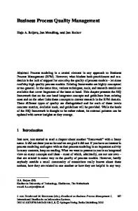
4.1 SCRUM, EKD and Pattern Description SCRUM patterns consist of SCRUM activities, roles and artifacts. Figure 14 lists key SCRUM activities. After describing these elements using EKD no-
Dynamic Relationships Management Journal, November 2013
41
Ron S. Kenett: Implementing SCRUM using Business Process Management and Pattern Analysis Methodologies
tation (see for example Figure 15 and 16) the elicitation and organisation of patterns in a pattern repository is discussed. Figure 14: High level view of SCRUM activities
A sample Sprint pattern: Context: You are a software developer or a coach managing a software development team where there is a high percentage of discovery, creativity or testing involved. Sprints are applicable for building systems, both new and existing, that allow partitioning of work, with clean interfacing, components or objects. We want every person on the team to understand the problem fully and to be aware of all the steps in development. This limits the size of the team and of the system developed. Trust is a core value in SCRUM, and especially important for the success of Sprints, so SelfSelectingTeams is a plus. During a sprint, we optimize communications and maximize information sharing in DailySCRUM. Each Sprint takes a pre-allocated amount of work from the Backlog. The team commits to it. As a rule nothing is added externally during a sprint. External additions are added to the global backlog. Issues resulting from the Sprint can also be added to the Backlog. A Sprint ends with a Demonstration of new functionality. Problem: We want to balance the need of developers to work undisturbed and the need for management and the customer to see real progress. Forces: For many people – project managers, customers, it is difficult to give up control and proof of
42
progress as provided in traditional development. It feels risky to do so; there is no guarantee that the team will deliver. Often, by the time systems are delivered, it is obsolete or it requires major changes. The problem is that input from the environment is mostly collected at the start of the project, while the user learns most using the system or intermediate releases. Solution: Give the developers the space to be creative, and to learn exploring the design space, doing their actual work, undisturbed by outside interruptions, free to adapt their way of working using opportunities and insights. At the same time keep the management and stakeholders confident by showing real progress instead of documents and report produced as proof. Do this in short cycles, Sprints, where part of the Backlog is allocated to a small team. In a Sprint, during a period of approximately 30 days, an agreed amount of work will be performed, to create a deliverable. During SprintPlanning a Backlog is assigned to Sprints by priority and by approximation of what can be accomplished during a month. Chunks of low cohesion and high coupling are selected. Focus is on enabling, rather than micromanagement. During the Sprint outside chaos is not allowed in the increment. The team, as they proceed, may change course and their way of working. By buffering them from the outside, we allow them to focus on the work at hand and on delivering the best they can and the best way they can, using their skill, experience and creativity. Each Sprint produces a visible and usable deliverable. This is demonstrated in DemoAfterSprint. An increment can be either intermediate or shippable, but it should stand on its own. The goal of a Sprint is to complete as much quality software as possible and to ensure real progress, not paper milestones as alibi. Sprints set up a safe environment and time slots where developers can work undisturbed by outside requests or opportunities. They also offer a pre-allocated piece of work that the customer, management and the user can trust to get a useful deliverable such as a working piece of code at the end
Dynamic Relationships Management Journal, November 2013
of the Sprint. The team focuses on the right things to do, management working on eliminating what stands in the way of doing in better. Rationale: Developers need time to work undisturbed, they need support for logistics and management and users need to stay convinced that real progress is made. Examples: ABC has have been using Sprints since January 2006 on a number of end-user-projects and for the development of a framework for database, document management and workflow. The Backlog is divided in Sprints that last about a month. At the end of each Sprint a working Smalltalk image is delivered with integration of all current applications. The team meets daily in DailySCRUM Meetings and Backlog is allocated after the DemoAfterSprint in a monthly meeting with the steering committee. Figure 15 presents the actor role diagram of the Product Owner and System Architect. It indicates
that Product Owners need to be coordinated by the System Architect at the product architecture level. Figure 15: The Product Owner and System Architect actor role diagram
Running a Sprint requires coordination between the Product Owner and the SCRUM Master. Figure 16 presents a role activity diagram for the role of the SCRUM Master, Product Owner and Sprint Team, in the context of a Sprint.
Figure 16: The Sprint role activity diagram
Dynamic Relationships Management Journal, November 2013
43
Ron S. Kenett: Implementing SCRUM using Business Process Management and Pattern Analysis Methodologies
4.2 Defining SCRUM Patterns
4.2.2 Constructing Reusable Components
When defining patterns, one needs to continually keep in mind two aspects. These are 1) how we propose to introduce and implement the pattern in the organisation and 2) the importance and relevance of issues being presented. Without these clarifying these two points for each pattern, they will be of no use. The purpose of the process of defining patterns is to produce a description of reusable components. This process is mainly concerned by (1) identifying potential reusable knowledge and (2) constructing the reusable component embedding this knowledge.
This activity mainly concerns the problems of specifying and organising reusable components. The specification of reusable components is based on techniques that facilitate reuse such as, abstraction, genericity and inheritance. These techniques try to balance the degree of reusability of the components with the effort that shall be made while effectively reusing the component. The organisation of the reusable components is driven towards the facilitation of the search and the retrieval of reusable components. 4.2.3 SCRUM Patterns Elicitation
4.2.1 Identifying Reusable Knowledge This activity is essential to the process of defining reusable components. There are two problems to be considered, namely: identifying the sources of knowledge that shall be used as the starting point for defining reusable knowledge and selecting the techniques that shall be used for extracting the reusable knowledge. Two types of technique have been proposed so far. One is based on the study of wide variety of existing products whereas the second is based domain oriented meta modelling approaches. The latter focuses on the definition of specific concepts for describing domain knowledge. Table 2: Stages in defining patterns Part of Pattern Stage
To minimise redundancy, it is not necessary to provide a full description of all patterns as provided for in the pattern template, already at stage one. The degree of detail should be increased as one moves through the stages. A scorecard for each candidate pattern should be completed (see Table 2).
Informal signature
Responsible actor
Other
1. Collect candidates
Problem Solution Context
Project Management
Initial EKD Model
2. Evaluate suitability
Initial draft
Name Forces Rationale Consequences
Domain experts
Thesaurus, initial guidelines
3. Derive structure, context and relationships
Verb Object Source Result Manner
Related patterns Related documents Contributing authors Hyperlinks Annotation Version
Knowledge engineer
4. Validation
All attributes fully validated
All attributes fully validated
Project Management, Domain experts
44
Formal signature
The following four-step procedure is proposed to define patterns. By “define” we mean the discovery, selection and demarcation of the relevant patterns. The stages are: 1. Collect candidates 2. Evaluate suitability 3. Derive structure 4. Validation
Dynamic Relationships Management Journal, November 2013
Complete guidelines
For each stage, the various stakeholders need to play specific roles, see Table 3. Table 3: Roles, tasks and actors for the stages in defining patterns
tential patterns may be compared in a systematic way according to commonly accepted criteria, so as to enable a satisfactorily informed decision.
4.3 SCRUM Pattern Repository and Reuse
A commonly recurring problem is the trade-off which is often made between, having "easily organised knowledge" which is inherently incomplete so as to be structured as compared to knowledge which reflects reality, which is often not easily structured or even understood. The choice is then, where on a knowledge continuum you wish to place yourself. Our approach tends to be somewhere between highly structured and unrealistic knowledge at one end and unstructured but realistic knowledge, in the half of the continuum towards the unstructured. In practical terms this means that when defining patterns it is more important that these reflect real problems and solutions rather than flashy and technically brilliant presentations.
In order to make the SCRUM generic knowledge easy to organise and access for the benefit of the organization one needs to systematise and structure the knowledge and experience gained in different parts of the company. The knowledge engineer's task is to provide a framework where po-
Knowledge, expressed by generic patterns, should facilitate the creativity process by reducing the need to "reinvent the wheel" when facing new problems and situations. The essence of the use of patterns is that they are applied to recurring problems. A pattern is of no use if it aims to solve a prob-
Role
Tasks
Project Management
Overall responsibility: • Initiate definition procedure • Facilitate communication between analysts and domain experts.
Knowledge engineer
• Provide EKD and Pattern methodological support. • Ensure structure and consistency with objectives, and method.
Domain experts
• Provide domain knowledge • Ensure validity.
Figure 17: The SCRUM Pattern indexing organisation (adapted from ELEKTRA project)
Dynamic Relationships Management Journal, November 2013
45
Ron S. Kenett: Implementing SCRUM using Business Process Management and Pattern Analysis Methodologies
Table 4: Pattern evaluation criteria Criteria
Sub-criteria
High Value
Medium Value
Low Value
Degree of triviality The degree to which the pattern addresses a problem which is of little importance because the problem or solution is obvious.
The pattern is concerned with issues that are or most likely will be of concern to other parts of the company.
While the pattern deals with a The pattern is concerned with a pertinent problem, the solution is problem which does warrant the already well known. creation of a pattern since it is so trivial with the proposed solution being obvious to domain experts.
Grade of implementability Extent that pattern is thought to be practical and implementable. Is change compatible with business strategy. Have trade-offs been taken into account
The pattern is useful in that it prescribes practical, easy to understand and implement solutions.
The pattern may be of some use despite some practical problems in implementation and some difficulty in understanding the solution.
Degree of confidentiality
The pattern does not disclose any Some information may be able to The pattern discloses sensitive confidential business be used by other projects. project information. information.
Degree of complexity The number of factors and the their relationships.
The pattern addresses only a few The pattern is complex but may manageable main concepts and still be useful in that the ideas. complexity is needed.
The large number of factors that affect the implementation of the solution minimises the chances that the solution can be implemented.
Addition of Value The local and global benefits accruing to the business with the implementation
The consequences of a successful The local and global benefits are implementation are great value unclear, difficult to determine or to the project directly affected as marginal. well as other projects
There are no local or global benefits or there is a conflict between these so that in total no value is added
Level of genericity Abstraction level of the problem that the pattern addresses
The pattern addresses a problem The pattern addresses a problem The pattern addresses a problem that is general enough for all the that applies only to part of the that is only relevant to the company. company. project in which it was discovered.
Grade of understandability Visualisable and identifiable
The pattern is easy for decisionmakers, domain experts and those to be affected, to comprehend.
The pattern is only partially understandable to decisionmakers, domain experts and those to be affected.
The pattern is incomprehensible to stakeholders
External compatibility The extent to which the pattern could be used by other companies
The pattern has taken into account differences in national, and organisational cultures and ways of working amongst identified future external users of the pattern.
The pattern has partially takes into account differences in national, and organisational cultures and ways of working amongst identified future external users of the pattern.
The pattern does not take into account differences in national, and organisational cultures and ways of working amongst identified future external users of the pattern.
Level of experience in their use
The pattern has been implemented within the company.
The pattern has been partially or The pattern has never been sporadically used. implemented.
Economic feasibility of the proposed solutions
Proposed solution is relatively easy to implement. Organisational support exists in terms of sufficient resources as well as managerial support. The solution is politically and socially acceptable .
Proposed solution is difficult but feasible to implement. Organisational support is lukewarm. Resources are available but may not be sufficient. There may exist political and social difficulties in making the pattern feasible.
Usefulness
The pattern is not usable. The solution is impractical and difficult to understand. The pattern only proposes "paperbased" change rather than real change
Quality
Cost
46
Proposed solution is not feasible. Organisational support will be difficult to obtain. The resources will not be made available. The existing difficult social and/or political climate would make an implementation impossible.
Dynamic Relationships Management Journal, November 2013
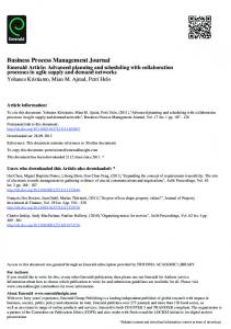
lem that is extremely unlikely to occur within the foreseeable future for those businesses that are envisaged to have access to the patterns. To enhance reuse, patterns need to be evaluated and assessed periodically. Table 4 presents a set of criteria that can be used to classify a pattern on a High-Medium-Low scale. The criteria focus on usefulness, quality and cost. Obviously each organisation should develop it’s own criteria, in line with it's strategy and organizational culture. Using patterns is an approach describing repeatable solutions to recognisable problems. In this context, both the problem and the solution must be uniquely identifiable and accessible. The pattern usage framework must therefore make the distinction between product or artifact patterns and process patterns, and includes an indexing schema for accessing them. The patterns typology aims to distinguish between the way to solve a problem and the elements that will be used for the solution, while the indexing hierarchy characterise each pattern by the problem that it addresses through the usage perspective and the knowledge perspective. The template in Table 1 represents the usage perspective and the EKD modelling presents the knowledge perspective. In order to enable reuse and pattern retrieved a signature is required in either a formal or informal format. An example of how this SCRUM patterns can be indexed and used in practice by specific projects within the enterprise is illustrated in Figure 17 which has been adapted from the ELEKTRA project. An example of an electronic patterns repository based on EKD is available in http://crinfo.univ-paris1.fr/EKD-CMMRoadMap/ index.html.
5. SUMMARY AND CONCLUSIONS Implementing agile development in general and SCRUM in particular in a large organization is a major challenge (Nerur, 2005; Tan & Teo, 2007). If this approach is considered a strategic initiative by the enterprise, one needs to formalize the approach by creating both a common language and a reuse repository of knowledge and experience. This paper presents a framework for applying EKD, a general Business Process Management description language
to map SCRUM patterns. By creating an organization-wide accessible SCRUM pattern repository, we are providing the infrastructure for company-wide implementation of agile development. Such a repository provides both storage and updating features that are critical for expanding SCRUM implementation beyond local islands of excellence. The gains achieved by this approach include improved knowledge management and increased efficiencies and competency model clarifications. The practical implications of integrating EKD and SCRUM are reflected by better communication between various role functions and increased accountability as a result of better defined job descriptions. The approach described in this work can also be applied to user groups and networks of small software developers who share an interest in better and faster software development practices. Specifically this can applied to communities developing open source software and help mitigates risks in such environments (Franch et al., 2013) In summary, the challenge of introducing structural changes in how organizations work is generically complex. The improvement of software and system development units is particularly challenging because of the abstract characteristics of the processes that require skills, experience, innovation and creative capabilities. Attempts to regulate such processes using standards like ISO 9000 are usually inefficient. On the other hand, addressing the problems of software and system development with a paradigm shift, like agile development, has proven effective (GAO, 2012). In order to deploy agile methods, the paper proposes an integration of SCRUM activities, Business Process Management (BPM) and Enterprise Knowledge Development (EKD) methods. This integrated approach is demonstrated with a real life case study. In particular, it is shown how to combine the elicitation and management of organizational patterns, as a basic element of knowledge management supporting this transformation. Process improvement in system and software development processes is a critical element in the competitive position of local and global organizations in this business area. Future research in these directions includes studies of how the experience of ABC Inc. can be replicated and adapted and how or-
Dynamic Relationships Management Journal, November 2013
47
Ron S. Kenett: Implementing SCRUM using Business Process Management and Pattern Analysis Methodologies
ganizational behavior and management experts can make further contributions to organizations struggling to meet such challenges. Acknowledgement: The author wishes to acknowledge the constructive comments of two refereed that helped improve the paper.
REFERENCES Alexander, C. (1979). The Timeless Way of Building. New York: Oxford University Press. April, A., Huffman Hayes, J., Abran, A., & Dumke, R. (2005). Software maintenance maturity model (smmm): the software maintenance process model. J. Softw. Maint. Evol., 17 (3): 197-223. Bach, J. (October, 1995). The Challenge of "Good Enough" Software, American Programmer. Berntsson-Svensson, R., & Aurum, A. (2006). Successful software project and products: An empirical investigation. Proceedings of ISESE ’06, ACM/IEEE international symposium on International symposium on empirical software engineering. New York, NY, USA: ACM Press: 144-153. Cohn, M., & Ford, D. (2003). Introducing an Agile Process to an Organization. IEEE Computer Society, http://www.mountaingoatsoftware.com/system/ article/file/10/IntroducingAnAgileProcess.pdf Coplien, J. (1994). Borland Software Craftsmanship: A New Look at Process, Quality and Productivity. Proceedings of the 5th Annual Borland International Conference, Orlando, Florida. Franch, X. (2013). Managing Risk in Open Source Software Adoption, ICSOFT2013, 8th International Joint Conference on Software technologies, Reykjavik, Iceland, http://riscoss.sites.ow2.org/bin/download/ Events/WebHome/ICSOFT-EA_2013_78_PROCS.pdf GAO 12-681(2012). Effective Practices and Federal Challenges in Applying Agile Methods, http://www.gao. gov/products/GAO-12-681. Kenett, R., & Baker, E. (1999). Software Process Quality: Management and Control. New York: M. Dekker. Kenett, R., & Baker, E. (2010). Process Improvement and CMMI for Systems and Software: Planning, Implementation, and Management, Taylor and Francis, Auerbach Publications. Nerur, S. & Mahapatra, R. (2005). Challenges of Migrating to Agile Methodologies. Communications of the ACM 48 (5): 72-78. Rolland, C., Nurcan, S., & Grosz, G. (1998). A unified framework for modelling co-operative design processes and co-operative business processes, in the Pro-
48
ceedings of the 31st Annual International Conference on System Sciences, Big Island, Hawaii, USA. Rolland, C., Nurcan, S., & Grosz, G. (1999). Enterprise Knowledge Development: the process view. Information and Management Journal, Elsevier 36 (3): 165-184. Rumbaugh, J. (1995). What Is a Method. Journal of Object Oriented Programming. Schwaber, K., & Beedle, M. (2001). Agile Software Development with Scrum, Prentice Hall. Stare, A. (2013). Agile project management – a future approach to the management of projects?. Dynamic Relationship Management Journal, 1 (2): 43-53. Takeuchi, H., & Nonaka, I. (1986). The New Product Development Game. Harvard Business Review, 69 (6): 96-104. Takeuchi, H., & Nonaka, I. (1995). The Knowledge Creating Company: How Japanese Companies Create the Dynamics of Innovation, Oxford University Press. Tan, C. H., & Teo, H. H. (2007). Training Future Software Developers to Acquire Agile Development Skills. Communications of the ACM 50 (12): 97-98.
Dynamic Relationships Management Journal, November 2013