Improved control valve sizing for multiphase flow. Special print from. “
Hydrocarbon Processing”. March 2005. By: Ralf Diener, BASF AG. Dr.-Ing. Jörg
Kiesbauer, ...
SAMSON Improved control valve sizing for multiphase flow
Special print from “Hydrocarbon Processing” March 2005 By: Ralf Diener, BASF AG Dr.-Ing. Jörg Kiesbauer, SAMSON AG Jürgen Schmidt, c/o BASF AG
Improved control valve sizing for multiphase flow Ralf Diener, BASF AG Jörg Kiesbauer, SAMSON AG Jürgen Schmidt, c/o BASF AG Control valves are frequently used in chemical and petrochemical plants to control medium mixtures which comprise a gas/vapor phase as well as a liquid phase as they enter the valve. The IEC 60534-2-1 Standard is primarily applied to calculate the required valve flow capacity (Cv or k v coefficient) for single-phase media in the form of gases or liquids. However, this standard does not apply to multiphase flow. A standardized sizing model does not exist even in literature. As a consequence, plant operators and manufacturers employ various published methods according to their own experience, which may lead to considerably different results depending on the operating and medium data involved. This article proposes a new approach to size control valves that handle multiphase mixtures consisting of gases/vapors and liquids. It takes into account how the change in density of the mixture flowing through the valve affects the flow capacity of the valve by using an expansion factor similar to the standard for gaseous media. It provides a high level of predictive accuracy when compared to test data. This expansion factor is easy to integrate into the IEC 60534-2-1 Standard.
Previous prediction methods The IEC 60534-2-1 Standard specifies that the required flow coefficient (kv) can be calculated using the following equation, provided the medium is not highly viscous and the pipeline upstream and downstream of the valve is straight [1, 2]:
⎛ ⎜⎜ ⎝
⎛ ⎜⎜ ⎝
⎛ ⎜⎜ ⎝
⎛ ⎜⎜ ⎝
(1)
The pressure difference between the inlet and outlet of the valve Δp0 as well as the density ρ0 apply to the reference condition of 1 bar and 1000 kg/m³. Y is the expansion factor and is equal to 1 for liquids, whereas it is related to the pressure difference for gases and vapors. Choked flow occurs when the pressure difference Δpmax is reached. Even if the pressure downstream of the valve is further reduced, the maximum, so-called critical mass flow rate cannot be increased. The pressure difference varies in compressible and non-compressible fluids [1, 2]. In cases where a multiphase flow comprising of gases and liq2
uids arises at the valve inlet the density ρ1 depends on gas/vapor void fraction and can no longer be uniquely defined. Mixture property data are no definite physical properties and therefore they can be defined in several ways. The addition model is the simplest method. It deals with each individual phase separately, calculating the flow coefficient of each phase according to the above equation. Both flow coefficients are then added together to result in an overall flow coefficient [2]. The correction factor proposed by Sheldon and Schuder [3] which is dependent on the volume share of the gas or vapor phase at the valve inlet raises the flow coefficients which are calculated too low in the addition model. Another prediction method arises from the concept that assumes both phases are equally mixed, i.e. homogeneous, and that they flow at a constant velocity. In this greatly simplified homogeneous model, the density ρ1 at the valve inlet is calculated, as demonstrated in Table 1 using ρ1=1/v1 [4] and then applied to the above equation (1). Special print from “Hydrocarbon Processing” · March 2005
The results of such simple model types deviate considerably from the measured data as stated in [2, 5]. A new approach based on more accurate physical assumptions is introduced in detail in [2, 5] which provides a much better prediction accuracy compared to the simple empirical methods. This method includes the following assumptions: • The change in the flow condition between the valve inlet and vena contracta is assumed to be frictionless and with no wall heat transfer (isentropic change of state). • In contrast, the flow in the area downstream of the vena contracta up to the valve outlet is viewed to be afflicted by losses. • Depending on the valve location, different flow patterns are assumed for calculation the mixture density (homogeneous density and momentum density at various flow velocities of the phases by using a special slip model). • The local mass flow quality of the flow is calculated from the changes in isenthalpic or isentropic state depending on the area of flow in the valve and applied to calculate the mixture density. • A non-equilibrium factor N is used to take into account the boiling delay and the thermodynamic non-equilibrium between the individual phases. The model requires an iterative solution of the mathematical equations and involves property data dependent on pressure and temperature (density, enthalpy, and entropy), which are only feasible in practice in certain cases. Therefore in this paper a simply applicable model based on the homogenous nonequilibrium Diener/Schmidt method (HNE-DS method) for the sizing of throttling devices in two-phase flow is proposed. The HNE-DS method extends the ω-method, originally developed by Leung, by adding a boiling delay coefficient to include the degree of thermodynamic non-equilibrium at the start of the nucleation of small vapor mass fractions upstream of the fitting. The additional introduction of a slip correction factor to take account of hydrodynamic non-equilibrium (slip) also makes it possible to calculate reliably the flow rate through control valves and orifices in both, flashing and non-flashing flow. In this paper the HNE-DS method is adapted to the equations of the IEC 60534-2-1 Standard. The essential calculation steps are outlined in the following section. New method for the IEC 60534-2-1 Standard using an expansion factor The new HNE-DS method basically assumes that the flow pattern in the control valve is homogeneous but gas and liquid are not in equilibrium – a non-equilibrium factor N represents the boiling delay. Compared to the more complex integration method by Diener [5] it is easier to apply in practice. Special print from “Hydrocarbon Processing” · March 2005
The assumption concerning the homogeneous flow and the introduction of the non-equilibrium factor allow for a calculation of the mass flux (mass flow rate W based on the area of the vena contracta Avc) without any iteration (see [6, 7] for exact derivation).
(2)
The compressibility coefficient ω contains operating (stagnation) conditions and property data as well as the non-equilibrium factor N: (3)
The area of the vena contracta Avc can be expressed using the flow coefficient as is usual in the IEC 60534 Standard: (4)
The pressure ratio p1/pvc increases as the pressure difference between inlet and outlet increases. The mass flow reaches its maximum and remain constant when the ratio of inlet and outlet pressure falls below the so-called critical pressure ratio. The critical pressure ratio (p1/pvc, crit) can be determined by resetting the first derivation of W/Avc according to (p1/pvc):
(5)
Table 1 contains an approximated equation for values of ω ≥ 2 in which an iterative solution of the above equation is avoided. The non-equilibrium factor N is approached on the basis of the measured data in [5] as a power law function, where is to be regarded as the vapor content in equilibrium state in the vena contracta for a critical flow. In [6, 7] an exponent of α=0.6 (travel < 25 mm) or α=0.4 (travel ≥ 25 mm) for control valves is proposed:
(6)
3
Based on the mass flow quality at the valve inlet, the increase of the equilibrium factor between the stagnation condition upstream of the valve inlet and the vena contracta can be determined with the assumption of an equilibrium state: (7)
As a result, equations are provided which allow the mass flow rate or flow coefficient to be calculated. As already mentioned, the boiling delay which affects the mass flow rate the most, is taken into account by the factor N for two-phase flashing flow. In [6, 7] the authors additionally propose using a slip correction factor φ for the hydrodynamic non-equilibrium of both phases, i.e., both phases have different flow velocities and are not homogeneously distributed.
(8)
with
(9)
To summarize, the following applies for the flow coefficient: (10a) or (10b) including the new expansion factor YMP for multiphase flow:
(11)
Step-by-step determination of the expansion factor YMP Table 1 shows the necessary input parameters and each step required to calculate the expansion factor as well as the mass 4
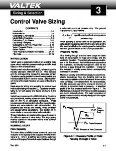
flow rate W or the flow coefficient k v. It is essential that the data , vg1, vl1, ∆hv1, cpl,1 related to the (stagnation) condition at the valve inlet are available. Similar to the method described in the IEC 60534 Standard, the differential pressure ratio x and the critical pressure ratio xCrit (∆pmax=p1 xCrit) are included in the new method. The generally unknown pressure pvc can be replaced with known parameters. As a result, the expansion factor is then derived directly from the differential pressure ratio x. The first step in the interim calculations is to determine the compressibility coefficient ω without the non-equilibrium factor N (i.e., N=1), and following this, xCrit and N and then the final compressibility coefficient ω. The critical pressure difference ratio xCrit can be directly determined for ω ≥2, in other cases, just in an iterative way using the second equation. Prediction example The following example in Table 2 illustrates a prediction to explain the procedure more clearly. Accuracy of the new approach The average predictive accuracy of the models is based on the values obtained for the variance of the logarithmic deviations between the experimental and calculated values, Table 3. The advantages of using this parameter are discussed in [5] and showed in the past to allow for a balanced description of the merits of each correlation. (f defines the independent number of variables in the model and can be neglected if n is greater than 500). In two-phase flow the real mass flow rate can be determined only by experiments, for example measurements made at the Technical University of Hamburg-Harburg, in the department of Prof. Dr. L. Friedel, and by SAMSON AG. There, the mass flow rate was measured when mixtures of steam and boiling water were passed through control valves. The test valves used had nominal diameters of 25, 50 and 80 mm and had different types of valve plug (V-port plug, parabolic plug and perforated plug). The test setups and the measuring methods and technology employed are described in [4]. In Fig. 1 the mass flow rates calculated by the complex method are plotted against the measured mass flow rates. The deviations are almost symetrically distributed on the diagonal. The variance of the logarithmic deviations amounts only 11 %. In opposite to this model allows the additon model and the model by Sheldon and Schuder no reasonable predictions, Fig. 2 and Fig. 3. The deviations are distributed asymetrically along the diagonal in a range from more than 100% underprediction up to even 100 % overprediction. The variance of the logarithmic deviations amount to more than 40 %. The new approach leads to a considerable improvement in Special print from “Hydrocarbon Processing” · March 2005
Vapor:
Input parameters
W
Recalculation of For ω ≥ 2: critical pressure difference ratio xcrit =1-pvc,crit/p1 for thermodynamic non- For ω < 2: equilibrium
kv
Gas ( = constant):
Inlet pressure
p1
Inlet temperature
T1
Outlet pressure
p2
Pressure difference
∆p=p1-p2
Mass flow rate
or
Flow coefficient Mass vapor or gas content [-] Specific volume of vapor or gas phase at the inlet (1/ρ)
vg1
Specific volume of liquid phase at the inlet (1/ρ)
vl1
Heat of vaporization in relation to p1 and T1 (liquid-vapor mixture only)
∆hv1
Final results Critical pressure difference Expansion factor YMP For Δp < Δpmax:
Specific heat capacity of liquid phase in relation cpl,1 to p1 and T1 (liquid-vapor mixture only) For Δp ≥ Δpmax:
Interim calculations Pressure difference ratio x Homogeneous specific volume of mixture
Flow coefficient k v
Slip correction factor φ
For Δp < Δpmax:
For Δp ≥ Δpmax:
Compressibility coefficient ω initially used for thermodynamic equilibrium (N=1)
For Δp < Δpmax: Mass flow rate W
Vapor: For Δp ≥ Δpmax: Gas ( = constant): Table 1: Parameters and equations used in the new model
Critical pressure difference ratio xcrit =1-pvc,crit/p1 initially used for thermodynamic equilibrium (N=1) Non-equilibrium factor N Vapor:
Gas ( = constant):
α=0.6 control valves with valve travel < 25 mm α=0.4 control valves with valve travel ≥ 25 mm N=1
Recalculation of compressibility coefficient ω Vapor:
Gas ( = constant):
ω=ωN=1
Special print from “Hydrocarbon Processing” · March 2005
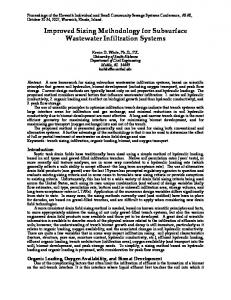
prediction accuracy compared to the methods mentioned in Section 2, Fig. 4. It achieves almost the same accuracy as the much more complex method shown in Fig. 1. The deviations are also almost symetrically distributed on the diagonal and the variance of the logarithmic φ deviations amount to almost 17 %. This value is acceptable for the control valve sizing because in most cases a safety margin of min. 20% is applied. Summary This article proposes a method to determine the flow coefficient or to predict the mass flow rate in valves controlling non-flashing two-phase flow or flashing two-phase flows. Similar to the existing IEC 60534 Standard for predicting the flow in control valves, the expansion factor applied to gas flows has been 5
Input parameters
Steam, control valve with FL = 1
Inlet pressure
p1=10 bar
Inlet temperature
T1= 182.89 °C
Outlet pressure
p2 = 5 bar
Pressure difference
Δp=10 – 5 = 5bar
Flow coefficient
10 m3/h
Mass vapor or gas content [-]
=0.01
Specific volume of vapor or gas phase at the inlet (1/ρ)
vg1 = 0.209 m3/kg
Specific volume of liquid phase at the inlet (1/ρ)
vl1 = 0.001128 m3/kg
Heat of vaporization Δhv1= 2,019 kJ/kg in relation to p1 and T1
extended to mixtures comprising gases/vapors and liquids. Just a small amount of additional information on physical property data is required for the calculation compared to the original method according to the IEC 60534 Standard. The entire steam table is not required. The results achieve a high level of accuracy which is sufficient for most engineering purposes. The authors will endeavor to integrate this method into Part 2-1 of the IEC 60534 Standard on its next revision. The method can, in principle, also be extended for a flow with more than two phases. However, the corresponding measured data are required. Statistical number Variance of logarithmic deviations
Definition
Specific heat of liquid cpl,1= 4,400 J/kg/K phase in relation to p1 and T1 Table 3: Definition of statistical number used to characterize the average predictive accuracy of the models
Interim calculations Pressure difference ratio x
x=(10 – 5)/10 = 0.5
Homogeneous v1=0.01x0.209 + specific mixed volume (1–0.01)0.001128 = 0.00321 m3/kg Slip correction factor φ
φ=1.26
Compressibility coefficient ω initially used for thermal equilibrium (N=1)
ωN=1=7.28
Critical pressure difference ratio xcrit=1-pvc,crit/p1 initially used for thermodynamic equilibrium (N=1)
xcrit, N=1=0.169
Non-equilibrium factor N:
N = 0.1194 (α=0.6, valve travel < 25 mm)
Recalculation of compressibility coefficient ω
ω=1.44
Recalculation of critical pressure difference ratio xcrit=1-pvc,crit/p1 for thermodynamic nonequilibrium
xcrit=0.38
Fig. 1: Accuracy of reproduction of control valve mass flow rates by means of the complex model by Diener for steam/water flow having low vapor content
Final results Critical pressure difference
Δpmax=3.47 bar
Expansion factor YMP
YMP=0.82
Mass flow rate W
W=8,558 kg/h
Table 2: Calculation example
6
Fig. 2: Accuracy of reproduction of control valve mass flow rates by means of the addition model for steam/water flow having low vapor content
Special print from “Hydrocarbon Processing” · March 2005
Fig. 3: Accuracy of reproduction of control valve mass flow rates by means of the Sheldon and Schuder for steam/water flow having low vapor content
[3] Sheldon, C.W., Schuder, C.B.: Sizing control valves for liquid-gas-mixtures, Instruments & Control Systems, Vol. 38, January 1965 [4] Heckle, M.: Zweiphasenströmung Gas/Flüssigkeit durch Drosselorgane. Ein neues Berechnungsverfahren der Zweiphasenströmung in Blenden, plötzlichen Verengungen und Ventilen (Two-phase gas/liquid flow through throttling devices), Fortschrittberichte der VDI-Zeitschriften, 1970 [5] Diener, R.: Berechnung und Messung der Massendurchsatzcharacteristik von Stellventilen bei Zweiphasenströmung (Experimental and calculated control valve two-phase mass flow characteristic), Fortschrittberichte VDI-Reihe 7, no. 388, 2000 [6] Diener, R., Schmidt, J.: Sizing of throttling device for gas/liquid twophase flow. Part 1: Safety valves, Process Safety Progress 23 (2004) 4, 335-344. [7] Diener, R., Schmidt, J.: Sizing of throttling device for gas/liquid twophase flow. Part 2: Control valves, orifices and nozzles, submitted to Process Safety Progress.
Dr.-Ing. Ralf Diener is senior plant manager of the ammonium carbonate plant in the division Inorganic Chemicals of BASF AG. His main fields of work include ammonium carbonate production, process support, and the further development of the products and the production plant. Previously he was involved with the development of calculation methods for safety-related problems. Address: BASF Aktiengesellschaft, E-CAA/SM - Q404, 67056 Ludwigshafen, Germany Phone: +49 0621 60-55889, Fax: -73646, E-mail:
[email protected] Fig. 4: Accuracy of reproduction of control valve mass flow rates by means of the new approach with the new expansion factor YMP based on the HNE-DS method with slip correction for steam/water flow having low vapor content
Literature: [1] Kiesbauer, J., Meffle, K.: Ein Leitfaden für eine vereinfachte Auslegung eines Stellgerätes auf der Basis von EN 60534 (An introduction to a simplified valve sizing based on the EN 60534 Standard), Automatisierungstechnische Praxis, Issue 8, 2001, Vol. 43, Oldenbourg Verlag, München [2] Diener, R., Friedel, L., Kiesbauer, J.: Auslegung von Stellgeräten bei Zweiphasenströmung (Sizing control valves for two-phase flow), Automatisierungstechnische Praxis, Issue 3, 2001, Vol. 42, Oldenbourg Verlag, München
Special print from “Hydrocarbon Processing” · March 2005
Dr.-Ing. Jörg Kiesbauer is Director of R&D at SAMSON AG MESS- UND REGELTECHNIK in Frankfurt/Main in Germany. His work experience includes R&D in the field of control valves equipped with electric and pneumatic accessories as well as self-operated regulators (flow and acoustical tests, development and optimization of calculation methods, development and testing of diagnosis tools for control valves etc., development of software tools). Since 1999, he has been involved in the IEC Working Group 65B-WG9 and in the DKE working group 963 as an expert. Phone: +49 69 4009-1464 E-mail:
[email protected] Dr.-Ing. Jürgen Schmidt works freelance in the Safety Engineering division at BASF AG as well as being active as a lecturer at the Technical University in Karlsruhe, Germany. For the past 11 years, he has worked at BASF AG in Ludwigshafen in the field of plant safety. He has been lecturing since 2002 in the subject of plant safety in the chemical industry and chairs the Dechema working committee for safety-related sizing of chemical plants. His key activities also include consulting companies in production process matters as well as the development of new methods in the field of safety engineering. Address: BASF Aktiengesellschaft, GCT/S-L511, 67056 Ludwigshafen, Germany Phone: +49 621 60-56205, E-mail:
[email protected]
7
2006-05 DR · WA 175 EN
SAMSON AG · MESS- UND REGELTECHNIK · Weismüllerstraße 3 · 60314 Frankfurt am Main · Germany Phone: +49 69 4009-0 · Fax: +49 69 4009-1507 · E-mail:
[email protected] · Internet: http://www.samson.de