1
2LE03
Improved Design and System Approach of a Three Phase Inductive HTS Fault Current Limiter for a 12 kVA Synchronous Generator Istvan Vajda, Attila Györe András Szalay, Vladimir Sokolovsky, Wolfgang Gawalek
Abstract–A further development of the high temperature superconducting (HTS) mini power plant (MPP) concept designed earlier by one of the authors is presented in the paper. HTS fault current limiters (FCL) will be inserted at the terminals of the synchronous generator. Joint operation of HTS generators (including fully superconducting generators) and HTS FCL’s provide additional benefits viz. a significant increase of the generator’s unit power rating as well as of its dynamic stability, shown in the paper. A three-phase inductive HTS FCL designed and built for the protection of a generator is made up of three one-phase units, each containing YBCO rings as secondary “windings”. A new design idea was applied for the primary winding to further reduce the leakage reactance of the FCL resulting in low reactive power consumption. Simulations of the electromagnetic processes in the HTS FCL are shown. Theoretical studies on the joint operation of a fully superconducting generator and an HTS FCL are presented. Index Terms–high temperature superconductor, fault current limiter, synchronous generator, fault currents, stability.
T
I.
INTRODUCTION
HE aim of the project carried out by the SuperTech Lab is to design, construct and test an all superconducting power complex (ASPC) realized in a superconducting (SC) mini power plant (MPP) model in the power rating range of 10 kW [1, 2]. The system consists of a superconducting generator, transformer, fault current limiter, motor and energy storage devices. ASPC’s like the MPP may be introduced into electrical energy systems in the medium term to help solve the problems of local energy supply, energy storage and reduce the environmental load. They enable reliable and uninterruptible energy supply for new information technology systems. The project involves the development of new task-specific high temperature superconducting materials and advanced technologies for the fabrication of samples and parts with improved properties to Manuscript received August 6, 2002. This work was supported in part by the Hungarian Academy of Sciences, under Grant No. T 032729 and by the Sydkraft AB, Sweden, Contrcat No. U-0002-09-Br (1997–) I. Vajda, A. Györe and A. Szalay are with the SuperTech Laboratory, Department of Electrical Machines and Drives, Budapest University of Technology and Economics, Egry József utca 18, H-1111, Budapest, Hungary (phone: +36-1-4632961, fax: +36-1-4633600, email:
[email protected]) V. Sokolovsky is with the Physics Department, Ben Gurion University of the Negev, Beer Sheva, Israel, PO Box 653, 84105 Beer Sheva, Israel (email:
[email protected]) W. Gawalek is with the IPHT Jena, Germany, PO Box. 100239, 07702 Jena, Germany (email:
[email protected])
meet specific power engineering application needs. The idea of SC or all superconducting (AS) complexes has forerunners [3, 4], however the concept and the planned realization of the superconducting MPP model is unique worldwide. The objectives include the studies of effective application of HTS devices, containing an evaluation of the technical and economical potential to promote market introduction. An important component of the MPP model is the three phase fault current limiter (FCL), which protects several devices, including an HTS synchronous generator unit. In this paper theoretical investigations of the joint operation of an HTS FCL and a fully superconducting (HTS) synchronous generator are presented. Experiments were accomplished on a three phase HTS FCL and a conventionally wound three phase synchronous generator unit. II.
DESIGN AND SIMULATION OF THE FCL
The FCL is a device, which can protect power equipment from high fault currents. A transformer type iron cored (with variable air gap) three phase FCL with YBCO secondary rings was built. For theoretical studies we assumed that the mentioned FCL protects a fully superconducting (both the excitation and the armature windings) generator. The FCL is connected to the terminals of the HTS generator. In normal operation mode the impedance of the transformer type FCL is the short circuit (appr. the leakage) impedance, while in steady state current limiting operation mode the impedance is the open circuit (appr. the main field) impedance. In normal operation the impedance of the FCL is much less, while in current limiting mode the impedance is higher than the impedance of the network. The FCL can be characterized by the impedance ratio of the two operation modes. The measured impedances are shown in Table I. TABLE I. PARAMETERS OF THE HTS FCL Parameters of the FCL Geometrical parameters of the Activation 5.2 A HTS ring current Inner Normal mode 31.3 mm 0.3 Ω diameter imp. @ 50 Hz Limitation mode Outer 41.3 mm 1.6 Ω imp. @ 50 Hz diameter Height 19.1 mm Ratio 5.33
2
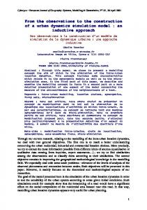
2LE03 A. Calculation of normal mode reactance When the HTS ring is in superconducting state, the FCL behaves similarly to a transformer with a secondary singleturn short circuited winding. As a result, the normal mode FCL reactance is approximately equal to the leakage reactance, which can be calculated as follows [5]: 28.4 ⋅ f ⋅ N12 ⋅ Dk ⋅ δ b ⋅ α (1) Xl = ⋅ 10 −7 g ⋅ lt where f is the frequency (50 Hz), N1 is the primary turn number, Dk is the average diameter of coil, δb is reduced width of leakage canal, α is the Rogowski-coefficient, g is number winding groups, lt is the width of coil. In normal operation mode, the reactive (and active) power consumption of the FCL should be reduced well below the same values of conventional current limiters like series chokes. According to (1) the leakage reactance can be significantly reduced if the number of coil pairs (g) is increased. For this purpose a so-called disk-type primary winding was designed and built with two winding groups, thus leakage reactance could be halved. B. The simulation of the FCL A typical FCL operation is the limitation of very high short circuit currents. Consequently, a detailed analysis of time dependent electromagnetic processes in the FCL is of special importance. For this purpose the FCL was simulated with the help of a 2D finite element method (FEM) software package, Flux2D. This package can simulate stationary and transient non-linear electromagnetic problems with coupling the studied device to external electrical circuits. The non-linear resistivity is expressed by means of an E-J power law (see Fig. 1.) as follows :
J c ( B) =
n( B ) =
J c0 B 1+ B0
n0 B 1+ B1
(3)
(4)
with 10 < Jc0 < 100 [kA/cm2], 1 < n0 < 50 B0 > 0 and B1 > 0 Jc0, n0, B0 and B1 are to be determined for the given HTS material. In our case, the parameters of the superconductor are as follows: Ec = 10-4 V/m, Jc0 = 4.4×10⁷ A/m2, B0 = 106 T (Bean model), n0 = 15, B1 = B0, ρ0 = 10-13 Ωm. The distribution of the magnetic flux lines were investigated for two different FCL designs. The first FCL has one primary winding. The dimension of the FCL is 175×140 mm and the dimension of the window is 52×97 mm, see Fig. 2. The second FCL has a disk type arrangement with two shared (disk type) primary windings. The external dimension of the FCL is 240×210 mm and the dimension of the window is 90×170 mm, see Fig. 3.
1 n ( B ) −1 E n( B) ρ ( E , B) = c E n( B) + ρ 0 J c ( B)
(2)
where Jc is the critical current density, Ec is the critical electric field, n the exponent, ρ0, is an additional resistivity. The value of the additional resistivity is limited, i.e. ρ0 = 10−13 Ωm.
Fig. 2. Flux density distribution for the cylindrical primary winding
Fig. 3. Flux density distribution for the disk type primary winding
Fig. 1. E-J power law of the HTS material used in the simulation
The Jc(B) and n(B) are expressed as follows:
The iron core, the superconductor ring and the magnetomotive force’s in the primary windings are same in the two cases.
3
2LE03 Figs. 2. and 3. indicate clearly the differences between the two designs (at the same flux line density). In the first case (Fig. 2.) the leakage reactance is much larger than that in the second case (Fig. 3.) where the FCL has two disk type primary winding groups (1.5 Ω→0.8 Ω). C. Fast operation of the FCL The FCL should have a very fast operation. For our experimental HTS FCL the activation time is 2 – 3 ms after a fault. This is less than the quarter of the network period. The simulation results for the current in the HTS ring during one cycle are shown in Fig. 4. Ampere 0.005E6
0
value of 2–3 times the nominal current. Consequently, the utilization of the HTS conductor and that of the whole generator is much better, which constitutes an additional benefit compared to those of individual HTS devices. For theoretical studies a 12 kVA, 230 V HTS FSSG was assumed with and without our inductive HTS FCL. The maximum armature current of the FSSG can be calculated according to [7]:
2 I max 1 = 2 I n 1 + 2 (1 − k ) ⋅ x d
where In is the rated current, k is the coefficient of coupling between stator and rotor windings, xd is the synchronous reactance per unit. The value of Imax1 shows the maximum current without FCL (independent short circuit current), which, in our case was 156 A. Setting the value of the limited current to twice the nominal current,
I max 2 =2 2I n -4.999E3
sec 0.005
0.01
0.015
s.
0.02
Fig. 4. The current in the HTS ring during one cycle (simulation)
Simulation results shown in Fig. 4. indicate that the HTS ring exhibits transitions from the superconducting to the normal, and back from the normal to the superconducting state within one half period. Such fast acting behavior of the HTS ring, and, as a consequence, of the FCL both into limiting and normal operation modes was observed in our tests published earlier [2, 6]. We have two supposes: the SC ring has double activation or the current increasing due to the closed magnetic circuit. III.
JOINT OPERATION OF AN HTS SYNCHRONOUS GENERATOR AND THE FCL
As we mentioned in the Introduction, the concept of the AS MPP involves the joint operation of several superconducting devices. One interesting device combination is that of a fully superconducting synchronous generator (FSSG) protected by an HTS FCL. Our theoretical considerations presented in this section show that the above combination will result in a better utilization of the HTS conductors used in the armature winding, and to an improved dynamic stability of the parallel operation of the FSSG. A. Design of the synchronous generator When designing the superconducting armature winding of an FSSG, the nominal current should be chosen so that the winding withstand the maximum current that may occur in any operational mode. In the most disadvantageous case of a sudden three-phase short circuit, the armature current can achieve 20–25 times the nominal current. As a result, current load for the HTS conductor should be chosen very low compared to the critical value. In contrast, when the envisioned FSSG is protected with our inductive HTS FCL, short circuit currents can be effectively limited down to a
(5)
(6)
the value of the FCL reactance (limiting mode) can be calculated from the following expression:
1+
2 =2 (1 − k ) ⋅ x d + x FCL 2
(7)
where xFCL is the per unit reactance of the FCL. The calculated value of the synchronous reactance of the FSSG was xd=0.5 p.u. Using (6) and (7), the reactance of the FCL should be equal to xFCL=1.625. With these values the allowable armature current of the FSSG protected by the HTS FCL can be increased by 3 times. B. Simulation of short circuits From the point of view of joint operation of FSSG and HTS FCL, the simulations and tests of asymmetrical loads and overloads, as well as short circuits are of special importance. Below we give a brief insight into this problem for the frequent case of a one-phase-to-ground fault. Test were performed on a conventional 12 kVA synchronous generator protected by our inductive HTS FCL. More details can be found in [8]. Simulation of a one-phase-to-ground fault For the simulation we applied the known method of the symmetrical components. This fault type can be treated as a combination of a shunt (short circuit) and series (insertion of xFCL) faults (simultaneous fault). The equations for the current and voltage components of the shunt fault are as follows: (8) I x1 = I x 2 = I x 0
U x1 + U x 2 + U x 0 = 0
(9)
The equations for the current and voltage components of the series fault are as follows:
Z ⋅ Ia 3 = Ia
Va1 = Va 2 = Va 0 =
(10)
I a1 + I a 2 + I a 0
(11)
4
2LE03 where Z is the impedance (limiting mode reactance) of the FCL. Fig. 5. shows the simulation results for an inductive load. One can see that limitation is effective in the faulty phase, and the currents in the faultless phases may increase. This increase may lead to the activation of FCL’s in the faultless phases. This activation can be considered as an unwanted operation, though it would result in a decrease of asymmetry, which is rather advantageous both from the point of view of the generator and the network.
IV. 1
2
18
Ampere
3
16
IC
14
IB
12 I a( ZÁK ) I b( ZÁK )
10
I c( ZÁK ) 8
IA
6
4
2
0
5
10
15
20
25
30
35
40
ZÁK Time [s]
Fig. 5. One-phase-to-ground fault with inductive load
C. Dynamic stability of the synchronous generator Finally, we have investigated the influence of the HTS FCL on the dynamic stability of superconducting generators. The generators posses reduced inertial constant in comparison with the traditional generators by 50-60% for 3000 rpm and by 60-70% for 1500 rpm and the constant of the turbine-generator block is decreased by a factor equal to 1.2-1.5. The decrease of this generator inertia may lead to disturbance of its synchronous operation under fault conditions where the normal operation of traditional generators is saved. Fig. 6. shows the calculation results that illustrate this. The three-phase fault event in one of the high voltage lines leads to disturbance of the normal operation of the system with superconducting generators but does not disturb the stability of operation of the traditional system. The application of a FCL allows to maintain the normal operation of the system. In the discussed cases FCL carries two functions: limits a fault current and increases dynamic stability of power system [9].
[1] [2]
[3] [4] [5] [6]
[7] [8] [9] Fig. 6. Influence of FCL on dynamic stability of power system: a – schema of power station; b – relative angle of the generator rotors vs. time: 1traditional generator without FCL; 2- superconductor generator without FCL; 3- superconducting generator with FCL.
CONCLUSIONS
The experimental HTS FCL is a fast operating device. Activation takes place within 5 ms (normally 2-3 ms). S-N or N-S transitions of the HTS ring take place each time whenever current goes beyond or below the critical current value. The normal mode impedance, and, as a consequence, the normal mode reactive power consumption was decreased by applying disk type primary winding; reactance is inversely proportional to the primary disk pairs. Joint operation of an HTS FCL and a fully superconducting synchronous generator results in the following advantages: 3.1 The utilization of the fully superconducting synchronous generator can be 3 to 5 times increased by installing an HTS FCL directly at the generator terminals. 3.2 The dynamic stability of the parallel operation of the generator can be increased without decreasing the static stability (instable generator w/o FCL can become stable with FCL). 3.3 Simulations and tests were performed for various overload and fault cases. In the case of one phase overloads the results were presented in the previous paper. Generalizing the results, the limitation of the current in the faulty phase may lead to an increase of the currents in the faultless phases. Our new recognition is that this effect can be advantageous since it can decrease the degree of asymmetry, both for the generator and the network. REFERENCES I Vajda, „Conceptual Design of an All Superconducting Mini Power Plant Model”, Proc. Delta 2002, M. Renovell et al (eds), Christchurch, New Zealand, 29–31 Jan 2002, pp. 267–271. A I. Vajda, S. Semperger, T. Porjesz, V. Sokolovsky, V. Meerovich, A. Szalay, W. Gawalek “Three Phase Inductive Fault Current Limiter for the Protection of a 12 kVA Synchronous Generator”, IEEE Trans App. Sup, 11, No. 1 2515-8 (2001). Fevrier, Y Laumond, Prospective Uses of Superconductors for 50/60 Hertz Applications, Proceedings of the ICEC 11, G. Klipping and I. Klipping, Eds, 1986, pp.139-52. W. V. Hassenzahl, “More Applications of Superconductivity to Electric Power Systems”, IEEE Power Engineering Review, vol. 20, No.6, 2000, pp.4-6. 8th Report for Sydkraft AB R&D Department, Vajda I (Ed), BME VGHT, 2001. November 27. V. Sokolovsky, V. Meerovich, I. Vajda, T. Porjesz, A. Szalay, “Operation of an HTS Fault Current Limiter in an Asymmetrical Three Phase System”, In: X. Obradors, F. Sandiumenge and J. Fontcuberta (eds.), Applied Superconductivity 1999, Inst. of Physics Conf. Series No. 167, 1, 963-6 (1999). Bristol and Philadelphia: Inst. of Physics Publishing. Y. Brunet, P. Tixador, T. Lecomte and J. L. Sabrie, „First Conclusion on the Advantages of Full Superconducting Synchronous Machines”, Electric Machines and Power Systems, 11, pp. 511–519 (1987) A. Gyore and I. Vajda, „Design Criteria for a Three Phase Inductive HTS Fault Current Limiter”, IEEE Postgraduate Power Conference, 12–14 Aug 2002, Budapest. V. Sokolovsky, V. Meerovich, and I. Vajda, „Superconducting Fault Current Limiter: State of Development and Possible Applications”, In: Advanced Studies on Superconducting Engineering, I. Vajda and L. Farkas (eds), SuperTech Consortium:Budapest, ISBN 963 420 695 6, pp. 253-271 (2001).