Sep 11, 2006 - arXiv:gr-qc/0601046v2 11 Sep 2006. Improved initial data for black hole binaries by ..... 1 )]} â 72 µrâ². 1bÏ {1 â râ². 1 b [. 1 + râ². 1 b. P1 (x1 râ².
Improved initial data for black hole binaries by asymptotic matching of post-Newtonian and perturbed black hole solutions Nicol´ as Yunes1 and Wolfgang Tichy2 1
arXiv:gr-qc/0601046v2 11 Sep 2006
Institute for Gravitational Physics and Geometry, Center for Gravitational Wave Physics, Department of Physics, The Pennsylvania State University, University Park, PA 16802-6300 2 Department of Physics, Florida Atlantic University, Boca Raton, FL 33431 (Dated: Id: paper.tex,v 1.118 2006/07/11 11:19:29 wolf Exp ) We construct approximate initial data for non-spinning black hole binary systems by asymptotically matching the 4-metrics of two tidally perturbed Schwarzschild solutions in isotropic coordinates to a resummed post-Newtonian 4-metric in ADMTT coordinates. The specific matching procedure used here closely follows the calculation in [1], and is performed in the so called buffer zone where both the post-Newtonian and the perturbed Schwarzschild approximations hold. The result is that both metrics agree in the buffer zone, up to the errors in the approximations. However, since isotropic coordinates are very similar to ADMTT coordinates, matching yields better results than in the previous calculation [1], where harmonic coordinates were used for the post-Newtonian 4-metric. In particular, not only does matching improve in the buffer zone, but due to the similarity between ADMTT and isotropic coordinates the two metrics are also close to each other near the black hole horizons. With the help of a transition function we also obtain a global smooth 4-metric which has errors on the order of the error introduced by the more accurate of the two approximations we match. This global smoothed out 4-metric is obtained in ADMTT coordinates which are not horizon penetrating. In addition, we construct a further coordinate transformation that takes the 4-metric from global ADMTT coordinates to new coordinates which are similar to Kerr-Schild coordinates near each black hole, but which remain ADMTT further away from the black holes. These new coordinates are horizon penetrating and lead, for example, to a lapse which is everywhere positive on the t = 0 slice. Such coordinates may be more useful in numerical simulations. PACS numbers: 04.20.Ex, 04.25.Dm, 04.25.Nx, 04.30.Db, 95.30.Sf
I.
INTRODUCTION
The modeling of binary black hole systems is essential for the detection of gravitational waves both by space and earth-based interferometers [2, 3, 4, 5, 6]. Often this detection relies on matched filtering, which consists of comparing accurate waveform templates to the signal. In the strong field regime, these templates can be modeled accurately enough only by numerical simulations [7], where one solves the Einstein equations subject to initial conditions that determine the physical character of the system. The astrophysical accuracy of the template generated via a numerical evolution will depend on two main factors: the numerical error introduced by the evolution and gravitational wave extraction codes; and the astrophysical accuracy of the initial data set. In this paper we study one particular approach to solve the initial data problem. This approach was developed in Ref. [1] (henceforth paper 1) and is based on matching several approximate solutions of the Einstein equations. There have been numerous efforts to find astrophysically accurate initial data for binary systems [8, 9, 10, 11, 12, 13, 14, 15, 16, 17, 18, 19, 20, 21, 22, 23, 24, 25, 26, 27], which usually consist of the 3-metric and extrinsic curvature. Most methods rely on performing decompositions of the data to separate the so called physical degrees of freedom from those constrained by the Einstein equations and those associated with diffeomorphisms. These
physical degrees of freedom carry the gravitational wave content of the data, and thus should be chosen to represent the astrophysical scenario that is being described. However, the exact solution to the Einstein equations for the 2-body scenario remains elusive. Therefore, the gravitational wave content of the data is not known exactly. One commonly used cure to this problem is to give an ansatz for these physical degrees of freedom, which usually does not satisfy the constraints. This ansatz is then projected onto the constraint-satisfying hypersurface by solving the constraint equations for the quantities introduced by the decomposition. The projected data will now satisfy the constraints, but it is unclear whether such data are astrophysically accurate. First, some of the assumptions that are used in the construction of the initial ansatz are known to be physically inaccurate. For example, the spatial metric is often assumed to be conformally flat, which is known to be incorrect at 2 post-Newtonian (PN) order [28], and which also does not contain realistic tidal deformations near the black holes. Furthermore, after projecting onto the constraint hypersurface, the data will be physically different from the initial ansatz [17, 18, 29]. It is thus unclear exactly what physical scenario these projected data represent and whether or not they will be realistic. Recent efforts have concentrated on using physical approximations to construct initial data sets. One such effort can be called the quasi-equilibrium approach [15, 20, 26] where one assumes that the quantities describ-
2 ing the initial data evolve on a time scale much longer than the orbital timescale, when appropriate coordinates are used. There are also approaches built entirely from second post-Newtonian approximations [17, 30]. Even though [17] also develops a complete method to project onto the constraint hypersurface, both [17] and [30] are not guaranteed to be realistic close to the black holes, since post-Newtonian theory is in principle not valid close to black holes. Another recent effort, which will be the subject of this work, involves several analytic approximations that are both physically accurate and close to the constraint hypersurface far and close to the holes (see paper 1). Such initial data coming from analytic approximations can then be evolved without solving the constraints, provided that constraint violations are everywhere smaller than numerical error. A perhaps more appealing alternative is to project these data onto the constraint hypersurface. If these data are close enough to the hypersurface, then any sensible projection algorithm should produce constraint-satisfying data that are close to the original approximate solution. Regardless of how such data are implemented, there are reasons to believe that such an approach will produce astrophysically realistic initial data. First, since the data are built from physical approximations, there are no assumptions that are unrealistic. The only limit to the accuracy is given by the order to which the approximations are taken. Moreover, the analytic control provided by these physical approximations allows for the tracking of errors in the physics, thus providing a means to measure the distance to the exact initial data set. Note however, that our work described below will only be accurate up to leading order in both the post-Newtonian and the tidal perturbation expansions used. This means that at the currently achieved expansion order, our initial data are by no means guaranteed to be superior to the other approaches discussed above. Nevertheless, our approach can be systematically extended to higher order. Data that use analytic approximations valid on the entire hypersurface are difficult to find because such approximations are usually valid only in certain regions of the hypersurface. One method to construct such data is by asymptotically matching two different physical approximations in a region where they overlap. Asymptotic matching, which for general relativity was developed in [31, 32, 33, 34, 35], consists of comparing the asymptotic approximations of two adjacent solution inside of an overlap 4-volume. By comparing these asymptotic approximations, matching returns a map between coordinates and parameters local to different regions, which forces adjacent solutions to be asymptotic to each other inside the overlap region called the buffer zone. Since these solutions are close to each other in the buffer zone, it is possible to construct transition functions that merge these solutions, thus generating a smooth global metric. Alvi [36] attempted to apply matching to binary systems, but instead of matching he actually performed patching, because he set the physical approximations
equal to each other at a 2-surface. As a result, Jansen and Br¨ ugmann [37] found that Alvi’s 4-metric, and in particular his extrinsic curvature, was hard to smooth with transition functions in the buffer zone, since the solutions were not sufficiently close to each other. Jansen and Br¨ ugmann thus concluded that these large discontinuities in Alvi’s data renders them impractical for numerical implementation. In paper 1, binary systems were studied once more, but this time true asymptotic matching was implemented, thus successfully generating solutions that approach each other in the buffer zone. It was possible to smooth these solutions and thus to create useful initial data. The approach we used in paper 1 was to match a PN metric in harmonic gauge [28], valid far from both black holes but less than a gravitational wavelength from the center of mass (near zone), to a perturbed Schwarzschild metric in isotropic coordinates, valid close to the holes (inner zone). In this paper, we study the method developed in paper 1 in more detail and we investigate and improve the resulting data. This improvement is mainly due to using different coordinates in the PN approximation. Instead of employing harmonic gauge, we now use a postNewtonian metric in ADMTT gauge [38, 39, 40]. We will see that this leads to better matching. The reason for this improvement is that the 4-metric in ADMTT coordinates can be brought into a form that is very close to Schwarzschild in isotropic coordinates near each black hole. Therefore, we obtain a much smoother match between this near zone metric and the inner zone one, which is also given in isotropic coordinates (see Fig. 2). The results presented in Sec. VI indeed show that matching with the ADMTT PN near zone metric works better than with the harmonic PN near zone metric. In addition, the ADMTT PN near zone metric is very similar to the perturbed Schwarzschild metric even near the black hole horizon, where PN approximations in principle break down. This similarity is due to the fact that, we use a resummed version of the ADMTT metric, obtained by adding higher order post-Newtonian terms. Another piece of evidence that suggests that matching works better between ADMTT and isotropic coordinates comes from looking at Hamiltonian and momentum constraint violations. In Sec. VII we compare the Hamiltonian and momentum constraint violations for the data of this paper and of paper 1. We find that the use of the ADMTT PN near zone metric leads to smaller constraint violations than in paper 1. With the help of a transition function we can also obtain a global smooth 4-metric which has errors on the order of the error introduced by the more accurate of the two approximations we match. By computing the constraint violations, we discover that both the data set of this paper and that presented in paper 1 might not be easily implemented in numerical simulations. In particular, we observe that the momentum constraint diverges near the apparent horizon of each black hole. This makes it difficult or impossible to ex-
3 cise a region inside each black hole, which contains all points where divergences occur. This divergence arises due to the choice of coordinates in the inner zone. Since we use the t = const slices of isotropic coordinates as spatial slices, the lapse goes through zero near the horizon. This zero in the lapse in turn leads to a blowup of some components of the extrinsic curvature and the momentum constraint. In order to circumvent this problem, we construct a map from isotropic coordinates to new horizon-penetrating coordinates. A similar idea was presented in Ref. [41], but here we extend those ideas and provide explicit expressions for the transformed inner zone metric in a ready-to-implement form. These new coordinates are identical Kerr-Schild coordinates inside the horizon and become isotropic in the buffer zone. When this transformation is applied to either the data set presented in this paper or that presented in paper 1, the lapse of the new t = const slices is positive through the horizon, eliminating the divergence in the extrinsic curvature. This new coordinate system will make excision easier, without changing the physical content of the data. The paper is organized as follows. Sec. II explains how the spacetime is divided into zones and how matching will be implemented. Sec. III describes the near zone postNewtonian metric, while Sec. IV focuses on the inner zone metric. Sec. V performs the matching and provides a map between coordinates and parameters local to the near and inner zones. Sec. VI gives explicit formulas for the global metric, introduces the smoothing functions and also decomposes this 4-metric into initial data for numerical relativity. Sec. VII compares the constraint violations of the initial data presented in this paper to those of paper 1. In Sec. VIII we present an additional coordinate transformation which can be used to construct horizon penetrating coordinates. Sec. IX concludes and points to future work. Throughout we use geometrized units, where G = c = 1.
II.
DIVISION OF SPACETIME INTO ZONES AND MATCHING IN GR
Consider a binary black hole spacetime and divide it into 4 zones. First, there are the so called inner zones C1 and C2 close to each black hole, where we can use black hole perturbation theory to obtain an approximate solution to the Einstein equations. These solutions are obtained under the assumption that the black holes are separated far enough that the influence of black hole 2 is only a small perturbation near black hole 1. Second, there is the near zone C3 where PN theory should provide a good approximation as long as the black holes do not move too fast. Finally C4 denotes the far zone where retardation effects matter. These zones are shown in Fig. 1 and we summarize them in Table I. The quantities introduced in this table are defined as follows: rin and rout are the approximate inner and outer boundary of each
y
Far Zone (C4)
Near Zone (C3)
0000000000 1111111111 Inner Zone BH 2 (C2) 0000000000 1111111111
Buffer Zone (O )
1111111111 0000000000 0000000000 1111111111 0000000000 1111111111 0000000000 1111111111 0000000000 1111111111 0000000000 1111111111 0000000000 1111111111 0000000000Buffer 1111111111 BH 2
13 111111 000000 000000 111111 000000 111111 000000 111111 000000 111111 000000 111111
BH 1
x
Inner Zone BH 1 (C1)
Zone (O ) 23
b FIG. 1: Schematic diagram of the near zone (dark gray), inner zones (light gray) and buffer zones (checkered). The near zone extends up to the inner boundary of the buffer zone, while the inner zone extends from the outer boundary of the buffer zone up to the black hole. Therefore, the buffer zones are spherical shells where the near zone and inner zones overlap. BH 1 and BH 2 (black) are separated by distance b.
Zone rin rout ǫ(n) Inner zone BH 1 (C1 ) 0 ≪b r¯1 /b Inner zone BH 2 (C2 ) 0 ≪b r¯2 /b Near zone (C3 ) ≫ mA ≪ λ/2π mA /rA Far zone (C4 ) ≫b ∞ mA /rA Table I: Description of the division of the spacetime into zones [36].
zone respectively, as measured from the Ath black hole (A = 1 or 2) in the coordinate system local to it; ǫ(n) is the expansion parameter used to find an approximate solution to the Einstein equations in that zone; mA is the mass parameter of the Ath black hole in the near and far zones; rA and r¯A are the radial distances as measured from the Ath hole in the near and inner zones respectively; λ is the typical gravitational wavelength; and b is the coordinate separation of the black holes. Inside of each zone we approximate the 4-metric with an monovariate expansion in ǫ(n) , which is defined in some coordinate system, and which depends on parameters, like the mass of the black holes or the orbital angular velocity. The inner zones are both equipped with isotropic coordinates and have parameters (MA , Ω), where the approximate solutions to the Einstein equations are given by a perturbed Schwarzschild metric. On the other hand, the near zone is equipped with ADMTT coordinates (ADMTT gauge), where the approximate solution to the Einstein equations is a PN approximation with parameters mA and ω. This PN approximation is valid in both C3 and C4 up to the order treated in this paper. As explained in paper 1, asymptotic matching consists of comparing the asymptotic expansions of adjacent ap-
4 proximate metrics in an overlap region or buffer zone. These buffer zones are defined by the intersection of the regions of validity of two adjacent metrics. The 2 buffer zones are delimited by the intersection of the inner zones C1 and C2 (of BHs 1 and 2), and the near zone C3 . These buffer zones O12 = C1 ∩ C2 and O13 = C1 ∩ C3 can only be defined in the asymptotic sense [42] via mA ≪ rA ≪ b and are the regions in which asymptotic matching will be performed. Formally, there is a third buffer zone (O34 ), given by the intersection of the near and far zone, but since the ADMTT PN metric at the order considered here is valid in both C3 and C4 , it is unnecessary to perform any matching there. The asymptotic expansions of the approximate metrics in the buffer zones OA3 are bivariate, because they will depend on 2 independent parameters: mA /rA and rA /b. Thus, the errors in the asymptotic expansions valid in the buffer zones will be denoted as O(p, q), which stands for errors of O(m/b)p or errors of O(rA /b)q . Asymptotic matching then produces a coordinate and parameter mapping between adjacent regions. In this paper, these maps will consist of a transformation between isotropic and ADMTT coordinates, as well as a set of conditions to relate MA and Ω to mA and ω. With these maps, we can construct a piece-wise global metric by choosing a 3-surface inside the buffer zone, where we join the approximate solutions to the Einstein equations together. Small discontinuities will be present in the global metric at the chosen 3-surface, due to its inherent piecewise nature, but they are of the same order as the errors in the physical approximations, and thus controllable by the size of the perturbation parameters. Furthermore, if such parameters are chosen sufficiently small, these errors could, in particular, become smaller than numerical discretization errors. Ultimately, a C ∞ metric is sought after, so, since these discontinuities are small, the global metric can be smoothed by introducing transition functions.
metric from the start, and thus it provides PN expressions for the lapse, shift, 3-metric and the conjugate momentum. We follow the conventions of Ref. [38] where the black hole trajectories from the center of mass of the system is given by m2 ~ ′′ ξ~1 (t′′ ) = b(t ), m
(1)
In Eq. (1), mA and m = m1 +m2 stand for the mass of BH A and the combined mass of the system in the ADMTT gauge, whereas the separation vector ~b(t) is given by ~b(t′′ ) = b (cos ωt′′ , sin ωt′′ , 0) .
(2)
Note that Eq. (2) assumes the black holes are initially in a circular orbit, which is a sensible approximation in the late stages of inspiral, since gravitational radiation will have circularized the orbit. The angular velocity of this orbit is given by Eq. (60) in Ref. [17]: � � m� p 1�µ 3 ω = m/b 1 + , (3) −3 2 m b
with errors of O(m/b)5/2 . In Eq. (3), µ = m1 m2 /m is the reduced mass of the system and b is the norm of the separation vector. This angular velocity is valid in the ADMTT gauge, which is different from the PN velocity used in paper 1, since the latter is valid only in harmonic coordinates. We further define the radial vector pointing from either black hole to a field point by y x z ), ~rA ′′ = (x′′ − ξA , y ′′ − ξA , z ′′ − ξA
(4)
where the double primed variables (t′′ , x′′ , y ′′ , z ′′ ) are inertial ADMTT coordinates measured from the center of mass. With these definitions, it is clear that ~r1 ′′ = ~r2 ′′ +~b, where ~b points from black hole 1 to 2. We also introduce the unit vector
III. NEAR ZONE: AN ADMTT POST-NEWTONIAN METRIC
In this section, we present the near zone metric in ADMTT gauge valid in C3 and C4 and expand it in the buffer zone O13 . Analyzing matching in O13 will suffice due to the symmetry of the problem. The coordinateparameter map for the overlap region O23 will later be given by a simple symmetry transformation. The ADMTT PN metric is obtained by solving the equations of motion for a binary black hole system with Hamiltonian dynamics [38]. The Hamiltonian is expanded in a slow-motion, weak-field approximation (PN) in ADMTT coordinates. This approach is similar to the standard Lagrangian PN expansion implemented in paper 1 and there exists a mapping between the two methods [28]. However, they differ in that the Hamiltonian formulation introduces a 3 + 1 decomposition of the 4-
m1 ξ~2 (t′′ ) = − ~b(t′′ ). m
~nA ′′ = ~rA ′′ /rA ′′ .
(5)
and the radial vector pointing from the center of mass to a field point r′′ = (x′′ , y ′′ , z ′′ ). The particle’s velocity vector is given by µ bω (− sin ωt′′ , cos ωt′′ , 0) . mA (6) The post-Newtonian near zone metric in inertial ADMTT coordinates (Eqs. (5. 4)-(5. 6) in Ref. [38]) can then be written as A+1
~vA ′′ = ∂t~rA ′′ = (−1)
(3)
gi′′ j ′′ = Ψ4 δij , (3)
(3)
′′
(3)
(3)
′′
g0′′ i′′ = gi′′ j ′′ β (3)j , g0′′ 0′′ = g0′′ i′′ β (3)i − (α(3) )2 , (7)
5 where we introduced a post-Newtonian conformal factor Ψ=1+
m2 m1 + ′′ . 2r1′′ 2r2
(8)
and where the post-Newtonian lapse and shift (Eqs.(5.4)(5.6) in Ref. [38]) are written as α(3) =
2−Ψ Ψ
(9)
and ′′
β (3)i
=
� � � m1 1 � i′′ ′′ ′′ i′′ i′′ v − ~ v · ~ n n − 4v 1 1 1 1 r1′′ 2 1 � � � � ′′ ′′ m2 1 i′′ + ′′ v2 − ~v2′′ · ~n′′2 ni2 − 4v2i . (10) r2 2
These expressions are accurate up to errors of O(m/rA )2 . The 3-metric is conformally flat and in the vicinity of each black hole (near rA = 0) the metric is very similar to the metric of a black hole in isotropic coordinates. Note that Ref. [38] uses units where 16πG = 1, but in Eq. (7) we use units where G = 1 instead. Also note that the PN expressions above are not pure Taylor expansions in m/r or v/c. Instead, certain higher order PN terms have been added to make the metric similar to the Schwarzschild metric in isotropic coordinates near each black hole. This resummation formally does not change the PN accuracy of the metric, but in practice it improves the PN metric since it yields a metric that is very similar to the inner zone black hole metric. The PN metric written in this form above even has apparent horizons near rA = mA /2. Later when we plot our results we will use this resummed form of the metric. The reader may worry that there is a certain arbitrariness in adding higher order terms. However, we have used the following two criteria to minimize this arbitrariness: i) We only add terms that would actually be present at higher PN order (compare [17, 38, 39, 40]). ii) The terms added have coefficients of order unity, and thus do not affect the usual PN order counting. Notice that point i) of course only means that we have added some higher order terms, not all higher order terms. The lapse and the spatial metric are similar to what was used in paper 1, when we expand them in the buffer zone. However, the shift given here is different from that in paper 1 and, thus, the maps returned by asymptotic matching will also be different. Now that we have the 4-metric in the near zone it is convenient to remove the frame rotation by performing the transformation t′′ x′′ y ′′ z ′′
= = = =
t, x cos ωt − y sin ωt, x sin ωt + y cos ωt, z,
where unprimed symbols stand for corotating ADMTT coordinates and double primed symbols correspond to the inertial ADMTT frame. After doing this coordinate change, the form of the near zone metric (7) as well as the lapse and conformal factor remain unchanged, with only the shift picking up an additional ω × r term and now becomes
β
(3)i
� � � m1 1 i i i = v − ~v1 · ~n1 n1 − 4v1 r1 2 1 � � � m2 1 i i i + v − ~v2 · ~n2 n2 − 4v2 r2 2 2 −ǫik3 ωxk ,
where ~vA and ~nA are now time independent and equal to the double primed versions at t = 0. In these coordinates, the magnitude of the radial vectors become
′′ rA = rA = x2A + y 2 + z 2
�1/2
,
(13)
where x1 = x − bm2 /m and x2 = x + bm1 /m. Let us now make one final coordinate transformation where we will shift the origin to the center of BH 1, i.e., m2 b , m ′ z = z,
x′ = x1 = x − y ′ = y,
t′ = t,
(14)
′ and rA = rA . The single-primed coordinates then stand for the shifted corotating ADMTT coordinate system. This coordinate change is useful because we will later concentrate on matching in O13 . We will usually make explicit reference to x1 instead of x′ to remind us that this distance should be measured from BH 1. This shift of the origin was not performed in paper 1 and, thus, the coordinate transformations that we will find will look slightly different. However, to O(m/b) this transformation should reduce to the results of paper 1 when the shift is undone.
We now concentrate on the overlap region (buffer zone) O13 . Inside O13 we can expand all terms proportional to 1/r2 in Legendre polynomials of the form � � �n ∞ � 1 r1′ x1 1X − P . = n r2′ b n=0 b r1′
(11)
(12)
Substituting Eq. (15) into Eq. (7), we obtain
(15)
6
(3) g˜0′ 0′
∼
(3)
g˜0′ 1′ ∼
(3)
g˜0′ 2′ ∼
(3)
g˜0′ 3′ ∼ (3)
g˜i′ j ′ ∼
"� # " � � � ′ �2 � �# �2 ′ m2 b r1′ x1 x1 2m2 r1 2m1 2 2 x1 + 1 + P1 + P2 +ω +y , −1 + ′ + r1 b b r1′ b r1′ m ! � � � � ��� ′ 2m1 r13 r1′ x1 2m2 1 µ y ′ x1 + mm2 b ′ −y ω 1 + ′ + 1− 3 1 + P1 − bω ′ r1 b b r1′ 2 r1′ b r12 # " � � �� ′ r′ x1 m1 r12 by m2 µ 1 + 3 1 P1 , + bω ′ 2 + ′ 2 2m r1 r1 b b b r1′ � � � � � ��� � � � � m2 b 2m1 r′ r1′ x1 x1 7µ 2m2 r1′ x1 + ω 1+ ′ + 1 + 1 P1 1 + − bω 1 − P 1 ′ ′ m r1 b b r 2 r1 b b r1′ ! 1 � ′ �2 � �#) ′ x1 1µ y2 r13 r , P2 − bω 1 − + 1 ′ b r1′ 2 r1′ b3 r12 � � 1µ yz r′ − ′ bω ′ 2 1 − 31 , 2 r1 r1 b ( " � � � ′ �2 � �#) 2m1 r1′ x1 x1 2m2 r1 1 + P1 δij 1 + ′ + + P2 , r1 b b r1′ b r1′
where all errors are of order O(2, 3) and where m1 ≪ r1 ≪ b. Eq. (16) is denoted with a tilde because it is the asymptotic expansion in the buffer zone around BH 1 of the ADMTT metric. This metric has now been expressed entirely in terms of the shifted corotating ADMTT coordinate system (x′ , y ′ , z ′ , t′ ). Note that Eq. (16) is a bivariate series, since it depends on two independent expansion parameters m1 /r1′ and r1′ /b. Since both expansion parameters must be small independently, Eq.(16) is valid in a 4-volume defined by the size of the buffer zone. IV.
INNER ZONE: A BLACK HOLE PERTURBATIVE METRIC
In this section we discuss the metric in the inner zone C1 of BH 1 and its asymptotic expansion in the overlap
(16)
region O13 . Since this metric will be the same as that used in the inner zone in paper 1, we will minimize its discussion and mostly refer to that paper. However, since we are using different notation than that used in paper 1, we will summarize here the principal formulas.
In the inner zone 1, let us use inertial isotropic coordi¯′ nates, labeled by xi = (¯ x′ , y¯′ , z¯′ , t¯′ ), which are centered at BH 1. Note that these coordinate are identical to the shifted corotated harmonic coordinates used in the near zone to zeroth order. Let us further denote the inner (1) zone metric by gµ¯′ ν¯′ , which will be given by a tidally perturbed Schwarzschild solution as
7
(1) g¯0′ ¯0′
≈
(1)
g¯0′ ¯1′ ≈ (1)
g¯0′ ¯2′ ≈ (1)
g¯0′ ¯3′ ≈ (1)
g¯i′ ¯j ′ ≈
�2 � �4 h i M1 m2 1 − M1 /(2¯ r1′ ) ′ ¯′ + y¯′ sin Ωt¯′ )2 − r¯1′2 , 1 − + 3 (¯ x cos Ω t − 1 + M1 /(2¯ r1′ ) b3 2¯ r1′ r � �2 � �4 � � � ′2 2m2 m M1 M1 1− ′ 1+ ′ ¯′ y¯′ cos Ωt¯′ , z¯ − y¯′2 sin Ωt¯′ − x 3 b b 2¯ r1 2¯ r1 r � �2 � �4 � ′2 � � M1 M1 2m2 m 1− ′ 1+ ′ x¯ − z¯′2 cos Ωt¯′ + x ¯′ y¯′ sin Ωt¯′ , b3 b 2¯ r1 2¯ r1 r � �2 � �4 M1 M1 2m2 m 1 − 1 + (¯ y ′ cos Ωt¯′ − x ¯′ sin Ωt¯′ ) z¯′ , b3 b 2¯ r1′ 2¯ r1′ ("� # � �4 �4 i 2 M1 M m2 h 2M 2 1 1 ′ ′ ′ ′ ′2 1+ ′ x cos Ωt¯ + y¯ sin Ωt¯ ) − r¯1 1+ ′ δij + 3 3 (¯ − ′2 δij 2¯ r1 b 2¯ r1 r¯1 )! � � ′ ′ 2M1 M12 x ¯i x ¯j − ′ 1 + ′2 , ′2 r¯1 4¯ r1 r¯1 �
where r¯1′ = (¯ x′2 + y¯′2 + z¯′2 )1/2 . This equation is identical to that used in the inner zone of paper 1 or Eq. (3.23) of Ref. [36]. This metric was first computed by Alvi [36] by linearly superposing a Schwarzschild metric to a tidal perturbation near BH 1. This perturbation is computed ′ as an expansion in ǫ1,2 = r¯1,2 /b and it represents the tidal effects of the external universe on BH 1. Since a simple linear superposition would not solve the Einstein equations, multiplicative scalar functions are introduced into the metric perturbation, which in turn are determined by solving the linearized Einstein equations. With these scalar functions, the metric then solves the linearized Einstein equations and it represents a tidally perturbed Schwarzschild black hole. This metrics has been found to be isomorphic to that computed by Poisson [43] in advanced Eddington-Finkelstein coordinates. Asymptotic matching will be easier when performed
between metrics in similar coordinate systems. We, thus, choose to make a coordinate transformation to corotating ¯ isotropic coordinates xi = (¯ x, y¯, z¯, t¯). The inner zone metric in corotating isotropic coordinates will be denoted (1) by gµ¯ν¯ and is given by � � Ω 2 (1) ¯ 2 x ¯2 + y¯2 + 2Hst x g¯0¯0 ≈ Ht + Hs1 Ω2 x ¯ + y¯2 − z¯2 , b � � ¯i Hst h � ¯3 ¯ ¯ (1) j ¯ + x¯2 − z¯2 δ¯i2 , g¯0¯i ≈ −Hs1 Ωǫ¯i¯j ¯3 x + 2 y¯ δ¯i z¯ − δ¯i1 x b ¯ ¯ xi xj (1) g¯i¯j ≈ δ¯i¯j Hs1 − Hs2 2 , (18) b where ǫ¯i¯j k¯ is the standard Levi-Civita symbol with convention ǫ¯1¯2¯3 = 1 and where δ¯ba¯ is the Kronecker delta. In Eq. (18) we use the shorthand
� �2 � �4 M1 M1 1− 1+ , 2¯ r1 2¯ r1 #) � � � "� �4 ( �4 M1 x ¯ m2 2 M1 M12 Hs1 = 1 + 1 + 2 3 r¯1 P2 1+ , −2 2 2¯ r1 b r¯1 2¯ r1 r¯1 � � �4 � � � x¯ M 2 4m2 M1 M1 1 + 12 , P2 Hs2 = 1 + 2¯ r1 4¯ r1 b¯ r1 r¯1 � � � �2 �4 � x¯ 1 − M1 /2¯ r1 M1 m2 2 Ht = − , r¯1 P2 +2 1− 3 1 + M1 /2¯ r1 2¯ r1 b r¯1 Hst = 2m2
r
(17)
m b3
where r¯1 = r¯1′ and the errors are still of O(¯ r1 /b)3 . These shorthands for the different components of the metric are identical to those used in paper 1.
(19)
We now need to asymptotically expand the inner zone metric in the buffer zone, i.e., as M1 /¯ r1 ≪ 1. Doing so
8 (1)
we obtain (1)
� � 2M1 x ¯ 2m2 + 3 r¯12 P2 r¯1 b r¯1 � +Ω2 x¯2 + y¯2 , r � � 2M1 −2m2 m , y¯x¯ − y¯Ω 1 + b3 b r¯1 r � � � 2M1 2m2 m 2 2 ¯Ω 1 + x ¯ − z¯ + x , b3 b r¯1 r 2m2 m z¯y¯, b3 b � � �� 2M1 2m2 2 x ¯ δij 1 + + 3 r¯1 P2 (20) r¯1 b r¯1
g˜¯0¯0 ∼ −1 +
(1)
g˜¯0¯1 ∼ (1)
g˜¯0¯2 ∼ (1)
g˜¯0¯3 ∼ (1) g˜¯i¯j
∼
(1)
The asymptotic expansion of gµ¯ν¯ will be denoted by
x ¯ ≈ y¯ ≈ z¯ ≈ t¯ ≈ M1 ≈ Ω ≈
g˜µ¯ν¯ . Note that this asymptotic expansion is a bivariate expansion in both r¯1 /b and M1 /¯ r1 . In other words, it is the asymptotic expansion in the buffer zone to the approximate solution in the inner zone.
V. MATCHING CONDITIONS AND COORDINATE TRANSFORMATIONS
In this section, we find the coordinate and parameter maps that relate adjacent solutions. Since the coordinate systems are similar to each other in the buffer zone, we make the following ansatz for the transformation between coordinates and parameters
� χ2 (x ) + χ1 (x ) + χ3 (x ) , x 1+ b b b � � � m �1/2 � m �3/2 �m � 2 2 2 ′ µ′ µ′ µ′ y 1+ γ2 (x ) + γ1 (x ) + γ3 (x ) , b b b � � � m �3/2 �m � � m �1/2 2 2 2 µ′ µ′ µ′ ′ ζ2 (x ) + ζ1 (x ) + ζ3 (x ) , z 1+ b b b � � � m �1/2 � m �3/2 �m � 2 2 2 ′ µ′ µ′ µ′ t 1+ τ2 (x ) + τ1 (x ) + τ3 (x ) , b b b � � � m �3/2 � m �1/2 m2 2 2 η1 + η3 , η2 + m1 1 + b b b � � m �1/2 � m �3/2 � m2 2 2 ω 1+ κ1 + κ3 , κ2 + b b b ′
�
� m �1/2 2
µ′
where, as in paper 1, χ1,2,3 , γ1,2,3 , ζ1,2,3 and τ1,2,3 are functions of the coordinates, whereas η1,2,3 and κ1,2,3 are coordinate independent. Note that this ansatz is slightly different from the one made in paper 1, because here we have shifted the origin of the near zone coordinate system, so that to zeroth order it agrees with the coordinates used in the inner zone. In order to determine these maps, we enforce the matching condition, i.e. � � ′ �� ∂ x ′ ¯ρ ∂ x ¯σ (3) (1) λ λ x x ¯ g˜µ′ ν ′ (xλ ) ∼ g˜ρ¯ , ¯σ ∂xµ′ ∂xν ′
(22)
which leads to a system of first-order coupled partial differential equations, which we solve order by order. The system to O(m/b)0 provides no information because both metrics are asymptotic to Minkowski spacetime to lowest order. The first non-trivial matching, occurs at O(m/b)1/2 . The differential system at this order and at order O(m/b) are similar to those obtain in paper 1 and we, thus, omit them here. The solution up to
�m � 2
µ′
� m �3/2 2
µ′
(21)
O(m/b) is given by � � � � � ′ m2 x′ m2 �3/2 x ¯ ≈ x′ 1 + 1− + χ3 (xµ ) b 2b b � m2 ′2 ′2 ′2 + 2 2t + y + z , 2b � � � � �m � � m2 �3/2 x′ 2 ′ µ′ y¯ ≈ y 1 + + 1− γ3 (x ) b b b r r m2 m2 ′ + t, b m � � � � �m �� x′ m2 �3/2 2 ′ µ′ z¯ ≈ z 1 + 1− + ζ3 (x ) , b b b � � � � � m �3/2 �m � x′ 2 2 µ′ ′ ¯ 1− + τ3 (x ) (23) , t ≈ t 1− b b b with η1 = 0 and κ1 = 0. We should note that in solving the differential system to O(m/b)1/2 and O(m/b) we have explicitly required that the coordinate system be not boosted or rotating with respect to each other. Fur-
9 thermore, we found the particular solution where the t′ = 0 and the t¯ = 0 slices coincide, since t′ = 0 implies t¯ = 0. We should also note that Eq. (23) of this paper is different from the transformation found in paper 1 because in this paper we have shifted the origin of the near zone coordinate system, which simplifies the transformation. Matching at O(m/b)3/2 needs to be performed only on the 0i components of the metric to get the first non-
� � � � � m1 y ′ h m2 m1 i y ′ x′ m1 b3 − 1 + 3 − 4 + − , − κ + 1 − 2 ′ b2 2m r13 m b m 2m � � � � � � � � r y ′2 m1 b3 m2 t′2 5 x′2 7 3 m2 1 m2 m z ′2 7m1 + 2 − + 2 + 2 + − − − +2 ∼ m2 b 2 4m 2 m b 2m r1′3 2 m 2 b b 2 m � � � � � � ′ x m2 3 m2 b µ 7m1 7m1 7m1 + κ2 − 1 + + − −1 + ′ − , + + − 2m b m 2m 2 m 2m r1 2m � � � � r m y ′ z ′ m1 b 3 ∼ −1 +1 . (24) m2 b2 2m r1′3
t′ τ3,x′ − x′ χ3,t′ ∼ t′ τ3,y′ − y ′ γ3,t′
t′ τ3,z′ − z ′ ζ3,t′
trivial correction to the extrinsic curvature. This order counting does not follow the standard post-Newtonian scheme and it is explained in more detail in paper 1. Since the near zone shift is different from that used in paper 1, the differential system obtained by imposing the matching condition of Eq. (22) is also different. This system is given by
r
m m2
�
Note that κ2 represents the degree of freedom associated with the angular velocity. For simplicity, we now set κ2 = 0. Also note that η2 , η3 and κ3 never enter the matching conditions to this order, so we set those quantities to zero. All the matching relations between the parameters local to different approximation have now been specified to O(m/b)2 , i.e. Ω ≈ ω,
M 1 ≈ m1 .
With these matching relations, we can now find a particular solution to Eqs. (24) and this set will produce matching. Once more, we choose constants of integration such that the t′ = 0 and the t¯ = 0 slices coincide. Doing so we obtain the solution
(25)
� � � �� � � � r x1 � � m2 �3/2 y� m2 m1 � 3m1 m yt m1 b3 m2 � 1− − − 4 + 1 − − − 1 + x ¯ ≈ x1 1 + b 2b b m2 b2 2m r31 m b m 2m � m2 + 2 2t2 + y 2 + z 2 , 2b � � � � � � � r h �m �� m z 2 7m1 5 x1 �i � m2 �3/2 y 2 m1 b 3 m2 t2 3 m2 1 2 y¯ ≈ y 1 + + 1− − + − + t − − − b b b m2 b2 4m 2 m b2 2m r 31 2 m 2 3b2 r r � � � � � � � x1 m2 3 m2 b m2 7m1 7m1 7m1 µ m2 m2 x2 7 + −1 + + − −1 + + +2 − + + t, − + 21 b 2 m 2m b m 2m 2 m 2m r1 2m b m � � � � �� r �m �� x1 � � m2 �3/2 m yt m1 b3 2 z¯ ≈ z 1 + 1− − − 1 + 1 , b b b m2 b2 2m r 31 h �m � � x1 �i 2 1− , (26) t¯ ≈ t 1 − b b where errors are of O(2, 3). As in paper 1, this coordinate transformation is singular at r1′ = 0. Note, however, that in Eq. (26) we have
replaced r1′ by q r 1 = r1′2 + 6m2 .
(27)
10 This replacement amounts to adding higher order terms to the coordinate transformation, which have no effect in the buffer zone at the current level of accuracy. Yet it has the advantage that the resulting coordinate transformation is now regular at r1′ = 0. Thus, the replacement does not affect asymptotic matching (in the buffer zone). It merely leads to an inner zone metric expressed in a better coordinate system. In paper 1 there was one term in the coordinate transformation that was singular at the location of the holes, whereas here there are 3 such singular terms. This increase in singular behavior is due to the ADMTT shift having more poles than the shift of paper 1. The shift of the origin into the complex plane, as introduced in Eq. (27), removes this singular behavior from the real line, while only introducing uncontrolled remainders at a higher order. We should also note that in Eq. (26), we undid the shift given by Eq. (14), so that we measure distances from the center of mass of the system. The coordinate transformations presented in Eq. (26) is only valid in O13 , but we can find the transformation in O23 by a simple symmetry transformation. This transformation is given by the following rules: substitute 1 ↔ 2 and x → −x,
y → −y,
z → z.
(28)
The set of matching conditions plus the coordinate transformation presented in Eqs. (25) and (26) are the end result of the matching scheme. Now that we have an approximate global metric, we can decompose it to provide initial data for numerical simulations. This decomposition consists of a foliation of the manifold with spacelike hypersurfaces, where we choose the slicing given by t = 0 = t¯. Notice that we have found a coordinate transformation that is consistent both with this foliation and with the condition mA ≪ rA ≪ b, valid in the buffer zone. Note that there is some freedom in the matching scheme at the order of accuracy of this paper. This freedom is rooted in that a different choice for the matching parameters (M and Ω) could be made. However, except for the κ2 term in Ω, this would have no effect on the coordinate transformation or the 4-metric at the orders considered here. Furthermore, one can show that the value of κ2 does not affect the physics of the initial data we will construct below. Above, the choice of κ2 = 0 was made in order to simplify the relation between the parameters of the two approximations. Specifically, it was chosen such that the angular velocity parameters of the two approximations are equal. This is, however, not the only possible choice. Fortunately, the choice of κ2 will not affect the initial data we will construct later, since both the 3-metric and the extrinsic curvature will change only by uncontrolled remainders of higher order. This happens for the following reasons. A non-zero κ2 would only change the spatial part of the coordinate transformation at O(m/b)3/2 , and thus would have no effect on the slicing. Since the leading order non-zero piece in the extrin-
sic curvature is already of O(m/b)3/2 and proportional to Ω, any change due to spatial coordinate transformations or parameter changes at O(m/b)3/2 will cause changes only at even higher order. For the 3-metric, coordinate transformations or parameter changes at O(m/b)3/2 will make a difference at order O(m/b)3/2 in the metric. We can, however, again neglect these changes, since the 3metric was only matched up to O(m/b). In conclusion, this means that any allowed change in the matching parameters will not affect the physics of the initial data sets constructed below. VI.
CONSTRUCTING A GLOBAL METRIC
In this section, we present the global metric, by performing the coordinate transformation found in the previous section on the inner zone metric. The piecewise metric in corotating ADMTT coordinates is given by (1) in C1 , gµν , (global) (2) (29) gµν ≈ in C2 , gµν , (3) gµν , in C3 . (3)
In Eq. (29), gµν denotes the near zone metric given in Eq. (7), but in unprimed corotating ADMTT coordi(1) (2) nates, whereas gµν and gµν stand for the inner zone metrics of BH 1 and 2 transformed to corotating ADMTT coordinates via Eq. (26). Explicitly, the inner zone metric is given by (1,2)
(1,2) gµν = gµ¯ν¯ Jµµ¯ Jνν¯ ,
(30)
where Jνµ¯ is the Jacobian of Eq. (26), namely Jνµ¯ =
∂xµ¯ . ∂xν
(31)
(1)
In Eq. (30), gµ¯ν¯ is the inner zone metric in corotating (2)
isotropic coordinates given by Eqs. (18), while gµ¯ν¯ can (1) be obtained by applying Eq. (28) to gµ¯ν¯ . Eq. (30) is (1) also expanded in paper 1 with the substitution hµν = (1) gµ¯ν¯ . Note that the Jacobian given in Appendix A will be different from that presented in paper 1 because the coordinate transformation is different. In the following we present plots of different metric components at time t¯ = t′ = 0. These plots are representative samples of the initial data and will show how well the matching procedure works. In most of these figures we choose to plot along the axis that connects the holes (the x-axis). We have checked that the behavior along other axis is qualitatively similar to that along the x-axis, as evidenced by the contour plots included in the section. Furthermore, we plot only the relevant components because either the other components vanish along the x-axis or they present similar behavior. Thus the components and axis chosen present the general behavior of the data.
11
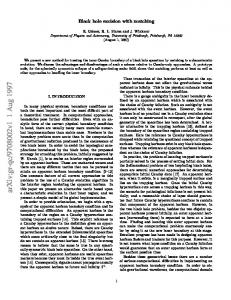
where S = r1 + r2 + b. These error bars were obtained by analyzing the next order term in the ADMTT PN metric and in the black hole perturbation approximation. In particular, the PN error is different from that used in paper 1. Here the first term comes from the expansion of the conformal factor and the last two from the 2 PN part of the transverse-traceless term in the ADMTT metric. The full PN error, given by the 3.5 ADMTT PN metric, is much more complex than the simplified approximation used in Enear , where the former contains some terms 3 2 that scale for example as m2A /rA and m3A /(SrA ). However, here we have neglected those terms and we have checked that Enear models well both the magnitude and functional behavior of the full error in the regions plotted in all figures with fractional errors of less than 1% everywhere. In Fig. 2, we plot the xx-component of the piece-wise metric along the positive x-axis. Observe that the inner zone metric of black hole 1 (dotted line) is close to the post-Newtonian near zone metric (dashed line) in the buffer zone of black hole 1 given by m1 ≪ r¯1 ≪ b. Recall that the definition of the buffer zone in the theory of asymptotic matching is inherently imprecise in the sense that as one approaches either the inner or outer radius of the buffer zone shell, one of the two approximations (i.e. near zone or inner zone metric) has much larger errors than the other. In our case we need both r¯A /b and mA /¯ rA to be small, which will not be the case at either end of the interval mA ≪ r¯A ≪ b. Hence we expect the best agreement between the two approximations to occur somewhere in the middle of each buffer zone shell. In fact the best agreement should occur where each of the
m1=m2=0.5m, b=10m
2
Inner zone 1 Near zone
1.8
gxx
For these plots, we choose two different physical systems. The first system consists of equal mass black holes separated by b = 10m. The two black holes are located at x = ±5m and are surrounded by apparent horizons, which approximately are coordinate spheres of radius m/4. For this system, some quantities, like the xxcomponent of the metric, are reflection symmetric under x → −x and we then plot only the positive x-axis, omitting the inner zone 2 data. The second system consists of two holes with mass ratio m2 /m1 = 0.25 separated by b = 20m. Here the holes are located at x = 4m and x = −16m, and surrounded by apparent horizons with radii of approximately m1 /2 and m2 /2 for holes 1 and 2 respectively. In general, a dashed line corresponds to the post-Newtonian near zone metric, while the dotted or dot-dot-dashed lines represent the perturbed Schwarzschild inner zone metrics. Most figures will contain error bars, which in the case of the metric are given by � � � � 3 m21 5 m1 m2 1 m22 1 Enear = + + + 2 r12 r22 4 b r1 r2 m1 m2 , −2 S2 m � rA �3 Einner,A = 2 , (32) b b
1.6
1.4
1.2 0
2
4
6
8
10
12
14
16
x/m FIG. 2: This figure shows the xx-component of the near zone (dashed line) and inner zone 1 metric (dotted line) along the positive x-axis in ADMTT coordinates. The black holes are located at x/m ≈ ±5 and the perturbative parameter is m/b = 1/10. Observe that the metrics become asymptotic to each other in the buffer zone, whose approximate center is roughly 4m away from each black hole. Also plotted are estimates of the error in the approximations. Note that the offdiagonal components of the 3-metric vanish along the x-axis for symmetry reasons, and that the yy- and zz-components are very similar to the xx-component.
two approximations have roughly the same error. From Fig. 2 we see that the inner zone metric of each black hole agrees with the near zone metric within error bars in the middle of each of the two buffer zones, where both have comparable errors. This agreement means that we have performed successful matching. However, our result in Fig. 2 is even better than this, since the near zone 3-metric is close to each of the inner zone 3-metrics even near the black holes, where post-Newtonian theory has large errors and is expected to fail. The reason for this somewhat surprising success near the black holes is that we have used resummed post-Newtonian expressions [Eqs. (7), (8), (9) and (10)] in the ADMTT gauge, which are very close to the isotropic Schwarzschild metric used in the inner zone. Note that the off-diagonal components of the 3-metric vanish along the x-axis for symmetry reasons, and that the yy- and zz-components are very similar to the xx component. The quality of the asymptotic matching (in the buffer zone) is equally good for all other components of the 4metric. This is evidenced in Figs. 3 and 4 which show the near and inner zone lapse and y-component of the shift, computed from the 4-metric (29) via β i = g ij goj . α = = gok β k − g00
�1/2
.
(33)
As one can see from Fig. 3 the near (dashed line) and inner zone 1 lapse (dotted line) agree well in the buffer
12 m1=m2=0.5m, b=10m
1
1.6 1.5
0.8
1.4
α
1.3
0.7
0.5 0
1.2
Inner zone 1 Near zone
0.6
2
4
6
8
10
12
14
16
x/m
0.4
-5
0
5
10
15
20
25
FIG. 5: This figure shows the xx component of the piecewise metric for a system of unequal masses and at larger separations. In particular, we have used m2 /m1 = 0.25 and b = 20m. Note that the matching improves since the perturbation parameter m/b is smaller.
addition, for most components (except the shift) the resummed post-Newtonian expressions [Eqs. (7), (8), (9) and (10)] we use in the near zone, follow the inner zone behavior even near the black holes, where this is not necessarily expected.
0.3 0.2 0.1
β
-15 -10
m1=m2=0.5m, b=10m
0.5
0
-0.1 -0.2
Near zone Inner zone 1
-0.3 -0.4 -0.5 0
1.1 -25 -20
x/m
FIG. 3: Plot of the lapse along the positive x-axis for the inner zone and near zone metrics. Note that the lapses are similar to each other not only in the buffer zone, but also near the hole.
y
Near zone Inner zone 1 Inner zone 2
gxx
0.9
m2/m1=0.25, b=20 m
2
4
6
8
10
12
14
16
x/m FIG. 4: Plot of the y-component of the shift along the positive x-axis for the inner zone and near zone metrics. Observe that although the inner zone and near zone curves are similar in the buffer zones, in this case they differ near the black holes. Also note that the x- and z-components of the shift vanish along the x-axis.
zone, located about 4m away from each black hole. Furthermore, the resummed expression [Eq. (9)] we use for the near zone lapse also is very close to the inner zone lapse near each black hole, where post-Newtonian theory has large error bars. In Fig. 4 we see that the near zone shift (dashed line) is close to the inner zone 1 shift (dotted line) in the buffer zone as expected after matching there. However, in the inner zone the post-Newtonian near zone shift is not valid anymore and deviates strongly from the inner zone shift. Thus in summary asymptotic matching works well for all components of the 4-metric in the buffer zone. In
We have also tested the coordinate and parameter maps for system with unequal masses and found that matching is still valid. Figure 5 shows the xx-component of the piece-wise metric along the entire x-axis for the case of m2 /m1 = 0.25 and b = 20m. Observe that the matching improves in this case because the perturbation parameter m/b has become smaller. Also note that the general features of the matching are the same as those presented in the equal mass case. We have plotted along the entire x-axis and show both the metrics of inner zone 1 (dotted line) and 2 (dot-dot-dashed line). Since we are interested in initial data on the t¯ = t′ = 0 slice we also have to discuss the extrinsic curvature given by
Kij = −
1 (∂t gij − £β gij ) . 2α
(34)
In the inner zones we use this equation to numerically (2) (1) compute Kij and Kij . Note however, that the inner zone extrinsic curvature in corotating isotropic coordi(1),ICC = nates can also be found in paper 1, where Kij (1)
K¯i¯j in the new notation. The near zone extrinsic curvature can easily be computed analytically from the near zone post-Newtonian
13 m2/m1=0.25, b=20m
m1=m2=0.5m, b=10m 0.009
Near zone Inner zone 1 Inner zone 2
0.04
0.006 0.02
m Kxy
m Kxy
0.003 0
0
-0.003 -0.02
Near zone Inner zone 1
-0.006
-0.04
-0.009 0
2
4
8
6
10
12
14
16
-25
-20
-15
-10
x/m
2 X 3 h i j j i 2 pA nA + pA nA 2rA A=1 i n i j −pm A nA δmn (δij − nA nA ) .
= Ψ−2
m2 b, m
v22 = −ω
m1 b, m
10
15
20
25
FIG. 7: This figure shows the xy component of the piece-wise extrinsic curvature for a system of unequal masses (m2 /m1 = 0.25) at separation b = 20m. Note that the scale of the y-axis has been reduced. The curves are closer to each other in this case because the perturbation parameter m/b has decreased by the choice of parameters.
(35)
i is of Bowen-York form, and vA and niA denote the particle velocities and directional vectors already introduced in Sec. III. On the t′ = 0 slice these quantities become
v12 = ω
5
black hole this agreement is within error bars, while between the holes the two error bars do not quite overlap. This suggests that a separation of b = 10m is at the edge of validity of the matching scheme employed here. Notice, however, that the error bars
4-metric in ADMTT coordinates. The result [17] (3)
0
x/m
FIG. 6: This figure shows the xy component of the near zone (dashed line) extrinsic curvature, as well as the inner zone curvature (dotted line) obtained via black hole perturbation theory. The plot is for equal mass black holes with m/b = 1/10. In the buffer zones, where the near and inner zone approximations have comparable error bars, the two approximations agree within error bars. All other components vanish along the x-axis.
Kij
-5
1 3 vA = vA = 0, (36)
EKP N
EKBHP T,A
� � � 5 m1 m2 1 m22 1 m21 + 3 + v + 2 r13 r2 4 b r12 r2 m1 m2 , −8v S3 � � m rA 3 v = 6 , (38) b b rA
3 = v 2
�
and k xk − ξA , rA 3 = ξA = 0.
nkA = 2 ξA
ξ11 =
m2 m1 b, ξ21 = − b, m m (37)
In Fig. 6 we plot the xy component of the extrinsic curvature along the positive x-axis in the equal mass case. For reasons of symmetry all other components vanish along the x-axis. Observe that the near zone solution (dashed line) diverges faster than the inner zone solution (dotted line). From this figure we see that even though the resummed ADMTT post-Newtonian expansion models well the 3-metric of a perturbed Schwarzschild hole, the ADMTT and inner extrinsic curvatures do not agree well in the inner zone, just like in the case of the shift. However, in the buffer zone where both inner and near zone results have similar errors, both approximations roughly agree. On the side away from the companion
plotted here (for v = (m/b)1/2 ) are only approximations of the true errors. These approximate errors were obtained by differentiating the error bars for the metric in Eq. (32) with respect to time. Note that the absolute error in the extrinsic curvature is O(m/b)1/2 smaller than that of the metric because the first non-trivial term in the extrinsic curvature appears at O(m/b)3/2 . Similar results for the extrinsic curvature are also obtained for different separations and mass ratios. Figure 7 shows the xy component of the piece-wise extrinsic curvature along the x-axis for the case of m2 /m1 = 0.25 and b = 20m. The near zone curvature (dashed line) agrees within error bars with the inner zone 1 curvature (dotted line) and the inner zone 2 curvature (dot-dot-dashed line) in buffer zones 1 and 2 respectively. Observe however, that the agreement worsens outside the buffer zone, e.g. as we approach either hole.
14 m1=m2=0.5m, b=10m
Transition Functions
In this subsection, we construct transition functions that allow us to remove the piece-wise nature of Eq. (29) and merge the approximate solutions smoothly in the buffer zone. This smoothing is performed by taking weighted averages of the two approximations. This procedure is justified by the fact that both approximations are equal to each other in the buffer zone up to uncontrolled remainders (asymptotic matching theorem [42]) which were neglected in the approximations used. In the following we assume that the middle of each buffer zone is located around �1/5 M = b4 m2A /m , (39) rA which corresponds to the distance from the black holes where the error bars of the adjacent approximations are comparable. The transition functions we use are all of the form 0,� r ≤ r0� 1 1 + tanh s tan( π (r − r0 )) 2 π �io 2w f (r) = (40) q2 , r0 < r < r0 + w − π tan( 2w (r−r0 )) 1, r ≥ r0 + w,
which is a function which smoothly transitions from zero to one in the region r0 < r < r0 +w. The parameters used here are as follows: r0 defines where the transition begins; w gives the width of the transition window; q determines the point where the transition function is equal to 1/2 (this happens at r1/2 = r0 + (2w/π) arctan q); the slope of the transition function at this point is s(1 + q 2 )/(2w) and thus can by influenced by choosing s (and of course w). The global merged 4-metric is then given by o n (global) (3) (1) gµν = G(x) F1 (¯ r1 )gµν + [1 − F1 (¯ r1 )] gµν n (3) + [1 − G(x)] F2 (¯ r2 )gµν + [1 o (2) , (41) −F2 (¯ r2 )] gµν
where we have introduced
FA (¯ rA ) = f (¯ rA ),
(42)
with M r0 = 0.4rA ,
M w = 3.5rA ,
q = 0.2,
s = b/m, (43)
and also G(x) = f (x),
(44)
but with b(m2 − m1 ) b − + 2.2m2 , w = b − 2.2m, 2m 2 q = 1, s = 2.5. (45)
r0 =
1
F1(r1) G(x) ~ Q1(r1)
0.8 0.6 0.4 0.2 0
-12 -10
-8
-6
-4
-2
0
2
~
4
6
8
10
12
r1/m, x/m, r1/m FIG. 8: This figure shows the transition functions used to merge the different pieces of the 4-metric. The transition function F1 (¯ r1 ) with the transition parameters of Eq. (43) is shown as a solid line, while the function G(x) with the parameters of Eq. (45) is shown with a dashed line. The transition function Q1 (˜ r1 ) (dotted line) defined in Eqs. (57) and (58) is used in Sec. VIII to construct horizon penetrating coordinates via the coordinate transformation (55).
The transition functions F1 (¯ r1 ) and G(x) are shown in Fig. 8 for mA = m/2, b = 10m and the parameters of Eqs. (43) and (45), respectively. The global lapse, shift and extrinsic curvature are merged using the same transition functions as for the 4metric above. With these transition functions, the global metric is a mixture of inner zone and near zone metric M M in a transition region given by 0.4rA < r¯A < 3.9rA . On the other hand, the global metric becomes identical to M the inner zone metric in the region r¯A < 0.4rA , while it becomes equal to the near zone metric in the region M r¯A > 3.9rA . Note that although the transition function are identical to those used in paper 1, the transition parameters chosen here are slightly different. This change is because the inner zone metric is very similar to the near zone metric close to the black holes in ADMTT coordinates, so that the transition region has been moved closer to the black holes. The exact choice of a transition function is to a certain degree arbitrary and could in principle be changed. However, the resulting global metrics generated by any other reasonable transition function should look very similar, and in fact be identical up to uncontrolled higher order post-Newtonian and tidal perturbation terms. Also note that the functions presented in this section are general enough to perform a smooth merge for systems with different masses and separations. In Fig. (9), we present the xx-component of the metric around BH 1. In this figure, the dotted curve corresponds to the inner zone metric, the dashed line is the near zone metric and the solid line is the merged global metric. The error bar in the global metric is given by the smallest of
15 m2/m1=0.25, b=20m
m1=m2=0.5m, b=10m
2
1.24
Near zone Inner zone 1 Global Metric
1.8
1.22 1.2
1.6
gxx
gxx
1.18
1.4
1.16 1.14 1.12
1.2
1.1 1 0
2
4
6
8 x/m
10
12
14
16
1.04 1.03
m1=m2=0.5m, b=10m Global rescaled metric Inner zone 1 Near zone
g xx /ψ
4
1.02 1.01 1 0.99 0.98 0.97 0.96 0.95 0
2
4
6
8
-5
0
10
5
15
20
25
x/m
FIG. 9: In this figure we show how the transition function takes the xx component of the near zone metric to the inner zone solution around BH 1. Observe that the transition function is smooth and does not introduce kinks into the global solution.
1.05
1.08 -10
Near zone Inner zone 1 Global metric
10
12
14
16
x/m FIG. 10: In this figure we show the x-component of the metric, divided by Ψ4 . The dashed line is the near zone metric, the dotted line is the inner zone metric and the black solid line is the global metric with transition functions.
the error bars of the respective approximations. The purpose of this figure is to show explicitly that the transition function effectively merges the different approximations in the buffer zone, where the errors are comparable. Even though the near zone 3-metric models the inner zone 3-metric well near the black hole horizons, the two metrics diverge differently at rA = 0. In Fig. 10, we plot the xx-component of the metric divided by Ψ4 . This denominator removes the divergence of the near zone metric, which now becomes identically unity, while showing that the inner zone metric differs by an amount equal to the size of the tidal perturbation near the horizon. The reason that the inner zone metric still diverges after di-
FIG. 11: In this figure we plot a system of unequal masses (m2 /m1 = 0.25) and a larger separation (b = 20m). We use the same parameters in the transition function as in the equal mass case.
viding by Ψ4 is due to the fact that the tidal perturbation piece of the inner zone metric is divergent at rA = 0. This happens because the tidal perturbation piece is valid only for finite space-like separations from the horizon, while rA = 0 which is located at the inner asymptotically flat end inside the black hole, is infinitely far from the horizon. This means that the tidal perturbation piece of the inner zone metric is not valid near rA = 0. Yet, if this spurious tidal perturbation is removed, the resulting 3-metric of the Schwarzschild background will again agree well with the resummed post-Newtonian near zone 3-metric. The same analysis can be performed for systems of unequal masses and at different separations. In Fig. 11 we plot the xx component of the metric along the xaxis for a binary with mass ratio m2 /m1 = 0.25 and at a separation b = 20m. The transition is now easier than before (note the scale of the y-axis), because the perturbation parameter has become smaller. Also note that we have used the same parameters in the transition function as those used in the equal mass case and the transition is still smooth. With these transition functions we can construct a smooth global metric, as shown in Fig. 12. There are no discontinuous features in the global metric. Just as in the case of the metric, to generate a global extrinsic curvature we will use the same transition function of the previous section with the same parameters. Figure 13 shows the global extrinsic curvature with the transition functions. Note that we could have computed the extrinsic curvature directly from Eq. (41), but this curvature would have been very similar to the curvature merged with transition functions. The difference between these two curvatures lies in the derivatives of the transition functions, but these terms will be of the same order or smaller than the uncontrolled remainders in either ap-
16
gxx isolines in xy-plane
Zone
8 6 4 2.5 1.6 1.43 1.3 1.25
Constraint Viol.
Physical Error
Inner zone BH1 (C1 ) O[(m/b)5/2 (¯ r1 /b)2 ] O[(m/b)(¯ r1 /b)3 ] 5/2 2 Inner zone BH2 (C2 ) O[(m/b) (¯ r2 /b) ] O[(m/b)(¯ r2 /b)3 ] 2 Near zone (C3 ) O(m/rA ) O(m/rA )2
2 0
y/m
-2
Table II: This table shows an order of magnitude estimate of the constraint violation of this data, together with the error in the physics.
-4 -6 0
2
4
6
8
10
12
-8 16
14
x/m FIG. 12: Contour plot of the xx-component of the global metric in the xy-plane around black hole 1 for the equal mass system. Apart from the singularity at x = ±5m, y = 0 the 3-metric is everywhere smooth. The different line styles correspond to different isolines of constant metric value.
Kxy isolines in xy-plane 8 6 4 0.00315 0.0025 0.0018 0 -0.002 -0.005
2 0
y/m
-2 -4 -6 -8
0
2
4
6
8
10
12
14
16
x/m FIG. 13: Contour plot of the xy component of the global extrinsic curvature in the xy-plane around hole 1 for the equal mass system. The different line styles correspond to different isolines of constant extrinsic curvature.
proximation in the buffer zone because of the parameter choice in Eqs. (43) and (45). (global) and the extrinsic curvature given The 3-metric gij in this section can now be used as initial data for black hole binaries. Recall, however, that these data are solutions to the Einstein equations only approximately and, thus, they only approximately satisfy the constraints. An analytic estimate of the constraint violation and physical accuracy of this data is given in Table II. Note that in the near zone, both the errors in the physics and the constraint violations are given by the neglected terms in the post-Newtonian approximation, which scale as O(m/rA )2 . On the other hand, in the inner zone, the leading error in the physics is due to the terms neglected in the perturbation, which
scales as O[(m/b)(r/b)3 ]. The inner zone constraint violations, however, are smaller, because the perturbed Schwarzschild metric used here, satisfies the Einstein Equations up to order O[(m/b)5/2 (r/b)2 ]. In order to obtain initial data that satisfy the constraints exactly, it will be necessary to project the data given in this paper to the constraint hypersurface. However, since these data are already significantly close to this hypersurface, sensible projection methods should not alter much the astrophysical content of the initial data. Furthermore, as stressed earlier, if this constraint violation is smaller than discretization error, these data could be evolved without any projection. There are a couple of caveats that need to be discussed in more detail. First, as in paper 1, asymptotic matching will break down when the separation of the bodies is small enough that the near zone disappears between the two black holes. An approximate criterion for when this happens, corresponds to the separation where the middles of the two buffer zone shells touch for the first time. If we define the middle of each buffer zone as in Eq. (39), this happens when the two spheres of radius r1M and r2M centered on each of the black holes, touch for the first time (roughly b ≈ 8m for an equal mass system). Furthermore, the tidal perturbation used in the inner zone metric is only valid for small spacelike separation from the horizon. This criterion implies that the tidal perturbation is good roughly for mA m mA ≪ r¯A ≪ b. 2 2b m
(46)
Therefore, numerical simulations will need to excise the data somewhere inside the apparent horizons of the black holes before evolving it, since the inner zone metric is not valid all the way up to r¯A = 0. Notice, however, that these limitations are due to the approximations and coordinates used and not due to asymptotic matching. VII.
CONSTRAINT VIOLATIONS
The initial data constructed here are based on approximate solutions and, thus, they do not solve the Einstein equations exactly. We have estimated that the largest error in the constraints of the full theory occurs in the buffer zone and is at most O(mA /b)2 . This error can be sufficiently small compared to other sources of numerical
17 0.009
Global (ADMTT) Global (harmonic)
0.03
0.006
0.01
0.003
0
0
m H
2
2
m H
0.02
-0.01 -0.02
Near zone Inner zone Global
-0.003 -0.006
-0.03
-0.009
-0.04
-0.012
-0.05 -0.06 0
2
4
6
8
10
12
14
16
x/m
-0.015 0
2
4
6
8
10
12
14
16
x/m
FIG. 14: This figure shows the violation of the Hamiltonian constraint for the equal mass system along the positive x-axis for both the data presented in this paper (solid black line) and that of paper 1 (dot-dashed black line).
FIG. 15: This figure shows the violation of the Hamiltonian constraint for the equal mass system along the positive x-axis for the near zone (dashed line), the inner zone (dotted line) and the global (solid line) data with transition functions.
error such that solving the constraints more accurately may not be required. On the other hand, the initial data could be used as input in one of the many conformal decompositions [14] to compute a numerical solution to the full constraints. In this section, we study the constraint violations of the data presented in this paper and we compare them to what was obtained in paper 1. In Fig. 14 we show the Hamiltonian constraint violation along the positive x-axis for both data sets. The solid line is the constraint violation produced by the data presented in this paper, while the dot-dashed line is that produced by the data of paper 1. Observe that far away from both holes, both data sets (paper 1 and this paper’s) have a constraint violation that approaches zero. This feature arises because both global metrics are given by a 1 PN solution in the near zone, which has a constraint violation that decays when the expansion parameter mA /rA becomes smaller. Note, however, that the constraint violation in ADMTT gauge is much smaller than in harmonic gauge. The reason for this difference is that our resummed PN expressions satisfy the Hamiltonian constraint up to errors of O(mA /rA )3 in ADMTT gauge, while the harmonic gauge expressions have errors of O(mA /rA )2 . Also in Fig. 14, observe that close to the holes, the violation is given by that of the inner zone solution, which is small near the horizon, but increases as we move away from the holes. The largest constraint violation occurs in the buffer zone, where we transition from inner to near zone expressions. Note that this maximum in the violation is mainly caused by the transition functions. As can be seen in Fig. 15, both the inner and near zone solutions individually have smaller constraint violations in the buffer zone than the global curve. This, however, is not an indication of a bad choice of transition functions. Rather the inner and near zone solutions have smaller constraint violations than expected, because we
have kept some extra higher order terms. Recall that matching in the buffer zone was only performed up errors of O(mA /rA )2 . Hence the two solutions differ by this amount, and thus the error in the physics is of the same order as well. Nevertheless, the inner zone solution has constraint violations of O(mA /rA )5/2 only, and the errors in the Hamiltonian constraint in the ADMTT near zone solution are only of O(mA /rA )3 . When these two solutions (which are equal to up to order O(mA /rA )) are averaged with a transition function we obtain a new solution which differs from both inner and near zone solution by O(mA /rA )2 . Therefore, we expect the error in the constraints of the averaged solution to be of O(mA /rA )2 as well, and thus larger than the error in the individual solutions. From Fig. 14 we see that the Hamiltonian constraint for the data of this paper is smaller than the data of paper 1. This decrease in the constraint violation is an indication that the matching performed in this paper produces near and inner zone solutions that are closer to each other in the buffer zone. Thus, the transition function has to do less work to join the solutions together, therefore introducing less of a constraint violation. We should point out that while the functional form of the transition function in paper 1 and in this paper is identical, the parameters used are different. The biggest difference is that here we use a smaller transition window w. Thus stronger artificial gradients and larger constraint violations might be expected in this work. This however, does not happen because matching works so much better in ADMTT coordinates that the inner and near zone solutions are substantially closer. Also note that the singularities in the constraint violations of the data in ADMTT and harmonic gauge (see Figs. 14 and 17) occur at different coordinate locations. This is simply because the inner zone metric, which is relevant in this region, is expressed in different coordinates.
18 1
H isolines in xy-plane
0
2
4
6
8
10
12
14
0.8
6
0.6
4
0.4
2
0.2
0
y/m
α
0.006 0.002 5e-05 -0.002
8
Inner zone 1 Near zone Global (ADMTT coords) Global (new coords)
0
-2
-0.2
-4
-0.4
-6
-0.6
-8
-0.8
16
-1 0
x/m
2
4
6
8
10
12
14
16
x/m FIG. 16: Hamiltonian constraint violation of the global metric in ADMTT coordinates in the xy-plane for the equal mass system. The different line styles corresponds to isolines of constant constraint violation.
Global (harmonic) Global (ADMTT)
0.006
2
m My
0.004
0.002
0 0
2
4
6
8
10
12
14
16
x/m FIG. 17: This figure shows the y-component of the momentum constraint violation along the positive x-axis for the data computed in this paper (solid black line) and in paper 1 (dotdashed black line), assuming the parameters of the equal mass system. Note that all other components vanish along this axis.
One obtains qualitatively similar plots if the constraints are plotted along different directions. Evidence for this behavior can be seen in Fig. 16, which shows a contour plot of Hamiltonian constraint violation for the global metric in ADMTT coordinates in the xy-plane. We see that there is ring of radius 3m of negative constraint violation around the black hole. Outside this ring, about 4.5m away from the hole, there are three maxima. The largest of these occurs on the x-axis. Note that these minima and maxima are all located in the buffer zone. In addition, there is a blow-up inside the horizon at rA = 0. In Fig. 17, we plot the y-component of the momentum constraint along the positive x-axis close to black hole 1 for both data sets. For reasons of symmetry all other components vanish along this axis. Observe that the violation is everywhere small, reaching a maximum
FIG. 18: This figure shows the near zone (dashed line), the inner zone (dotted line) and the global lapse (solid line) along the positive x-axis in ADMTT coordinates for the equal mass system. Observe that the global ADMTT lapse crosses zero near the horizon. Also shown is the lapse (dash-dash-dotted line) in the new horizon-penetrating coordinates of Sec. VIII.
in the buffer zone. As expected, in the near zone the violation decays as we move away from the black holes and becomes identically post-Newtonian. Note however, that the resummed PN data in ADMTT gauge satisfy the momentum constraint exactly, while in harmonic gauge it has an error of O(mA /rA )2 . On the other hand, in the inner zone, the violation is close to zero outside the horizon (which is located at rA ≈ mA /2) and it grows as rA becomes larger. As in the case of the Hamiltonian constraint the largest violation occurs in the region where the transition function leads to non-trivial averaging of the two approximations. The violation is once more smaller for the data presented in this paper relative to that of paper 1, which is one more indication that the matching is smoother here. Finally, observe that close to the holes, and in particular close to the horizons, the violation due to the inner zone data diverges. This divergence can be traced back to the choice of slicing, which forces the lapse to be zero at the horizon. The vanishing of the lapse can be observed in Fig. 18, where we plot the inner zone, near zone and global lapse along the positive x-axis. This figure shows how the inner zone lapse goes through zero near the horizon. The vanishing of the lapse translates into a divergence of the momentum constraint, which renders excision difficult and the data difficult to implement numerically. However, this is a failure of the coordinate system used in the inner zone and not of the method of asymptotic matching. In the next section, we construct a new coordinate system in which the lapse remains non-zero across the horizon, and approaches an isotropic Schwarzschild lapse in the buffer zone to allow for matching. In Figs. 14 and 17 we have compared the constraint violation of the data set presented here to that presented in paper 1. Technically this comparison suffers from the
19 problem that the constraints were computed in different coordinate systems. Note however, that both coordinate systems are identical to leading order. Yet instead of comparing the violations point by point, we can study their global average. Figs. 14 and 17 favor the data of this paper because the humps are consistently smaller. As explained earlier, this is an indication that after performing the matching, the inner and near zone solutions are very close to each other, making the transition smoother.
ing isotropic in the buffer zone. In this manner, the transformed inner zone metric components in the buffer zone will remain identical to those in Sec. V, so that we can use the same matching coordinate transformation [Eq. (26)] as in Sec. V. The standard transformation between spherical KerrSchild (tˆ′ , rˆ1′ ) and spherical isotropic coordinates (t¯, r¯1 ) centered at hole 1 and its inverse are given by [44]
VIII.
HORIZON PENETRATING COORDINATES
Recall that the global coordinate system constructed in Sec. V was based on matching the tidally perturbed black hole metric of the inner zone in isotropic coordinates to a post-Newtonian metric in ADMTT coordinates in the near zone. We have chosen to match in these coordinates because they are already very similar to each other. Hence, the coordinate transformation [Eq. (26)] that leads to matching is close to the identity, and thus facilitates computations. However, the fact that the global coordinate system remains very close to isotropic coordinates is also a disadvantage, since the t = 0 slice is not horizon penetrating in isotropic coordinates. The lapse goes through zero very close to the horizon and in addition, the extrinsic curvature has a coordinate singularity at the point where the lapse goes through zero. Initial data on such a slice may not be suitable for numerical evolutions. In this section we present a remedy for this problem. By constructing a further coordinate transformation, we obtain coordinates which are close to horizon penetrating Kerr-Schild coordinates near each black hole. The basic strategy we will use is the following. We first determine the perturbed black hole metric valid in the inner zone in Kerr-Schild coordinates. We then transform this metric into a coordinate system which remains KerrSchild near the black hole horizons, but which is corotat-
�
� r¯1 2 ψ(¯ r1 ) − 1 , rˆ1′ = r¯1 ψ(¯ r1 )2 , 2M1 � ′ � rˆ1 rˆ1′ t¯ = tˆ′ − 2M1 ln −1 , r¯1 = , 2M1 ψ(ˆ r1′ )2 θ¯ = θˆ′ , φ¯ = φˆ′ , (47)
tˆ′ = t¯ + 2M1 ln
where the radius is measured from the center of a black hole with mass M1 and where the conformal factor and its inverse are given by M1 , 2¯ r " 1 � �1/2 # rˆ1′ 2M1 ′ ψ(ˆ r1 ) = 1− 1− ′ . M1 rˆ1
ψ(¯ r1 ) = 1 +
(48)
Note that the inverse transformation contains a square root in the conformal factor, which becomes complex inside the horizon. For this reason, it is simpler to first transform the inner zone metric to Kerr-Schild coordinates analytically. Then, we can construct a new coordinate system that is the identity map near the horizon, but that brings back the metric to isotropic coordinates outside the horizon in the buffer zone. Let us first transform the inner zone metric of hole 1 to Kerr-Schild coordinates. By applying Eqs. (47) to the inner zone metric in spherical isotropic coordinates [Eq. (3.22) of Ref. [36]] we obtain
20
(1) gˆ0′ ˆ0′
=
(1)
gˆ1′ ˆ1′ = (1)
gˆ2′ ˆ2′ = (1)
gˆ3′ ˆ3′ = (1)
gˆ0′ ˆ1′ = (1)
gˆ0′ ˆ2′ = (1)
gˆ0′ ˆ3′ = (1)
gˆ1′ ˆ2′ =
� � � �2 m2 ′2 2 2 ˆ′ ′ ′ ˆ ˆ −f + 3 rˆ1 f 3 sin θ cos φ cos Ωt¯ + sin φ sin Ωt¯ − 1 , b � �� � � �2 m2 4M 2 (2 − f ) + 3 rˆ1′2 1 + ′21 3 sin2 θˆ′ cos φˆ′ cos Ωt¯ + sin φˆ′ sin Ωt¯ − 1 , b rˆ1 � � � �2 m 2 rˆ1′2 + 3 rˆ1′2 f 2 3 sin2 θˆ′ cos φˆ′ cos Ωt¯ + sin φˆ′ sin Ωt¯ − 1 , b (1) gˆ2′ ˆ2′ sin θˆ′ , � � � �2 m2 ′2 2M1 2M1 ′ ′ 2 ˆ′ ˆ ˆ ¯ ¯ − 3 rˆ1 f ′ 3 sin θ cos φ cos Ωt + sin φ sin Ωt − 1 , rˆ1′ b rˆ1 r � � 2m2 m ′3 − 3 rˆ1 f cos θˆ′ sin φˆ′ cos Ωt¯ − cos φˆ′ sin Ωt¯ , b b r � � 2m2 m ′3 − 3 rˆ1 f sin θˆ′ cos 2θˆ′ cos φˆ′ cos Ωt¯ + sin φˆ′ sin Ωt¯ , b b 1 (1) 1 (1) (1) gˆ1′ ˆ3′ = gˆ0′ ˆ3′ , g , f ˆ0′ ˆ2′ f
where all coordinates are centered on BH 1 and where we used the abbreviation � � 2M1 f = 1− ′ . (50) rˆ1 In Eq. (49), t¯ stands for the isotropic time coordinate, given in Eq. (47). Recall that this metric was derived under the assumption that the second black hole responsible for the tidal perturbation is moving slowly. In particular Alvi obtained the perturbation from a stationary perturbation by replacing φ¯ by φ¯ − Ωt¯. This means the largest error in this perturbation is of order O(m/b)5/2 O(rA /b)2 . In the following we will replace Schwarzschild time t¯ by Kerr-Schild time tˆ to simplify our expressions. This re-
(49)
placement will change the tidal perturbation only at order O(m/b)5/2 O(rA /b)2 and thus not introduce any extra errors. We now go one step further and transform Eq. (49) to Cartesian Kerr-Schild coordinates via the standard map �1/2 , rˆ1′ = x ˆ2 + yˆ2 + zˆ2 " # zˆ θˆ′ = cos−1 , (ˆ x2 + yˆ2 + zˆ2 )1/2 � � yˆ ′ −1 ˆ . φ = tan x ˆ tˆ′ = tˆ,
We then obtain
(51)
21
(1)
(KS)
(1) gˆ1ˆ1
(KS) gˆ1ˆ1
gˆ0ˆ0 − gˆ0ˆ0 −
m2 2 f d, b3 � m2 = 3 d 1+ b � m2 = 3 d 1+ b � m2 = 3 d 1+ b =
(1)
(KS)
(1)
(KS)
(1)
(KS)
=
(1)
(KS)
=
(1)
(KS)
=
(1)
(KS)
=
(1)
(KS)
=
(1)
(KS)
=
gˆ2ˆ2 − gˆ2ˆ2 gˆ3ˆ3 − gˆ3ˆ3 gˆ0ˆ1 − gˆ0ˆ1
gˆ0ˆ2 − gˆ0ˆ2
gˆ0ˆ3 − gˆ0ˆ3 gˆ1ˆ2 − gˆ1ˆ2
gˆ1ˆ3 − gˆ1ˆ3
gˆ2ˆ3 − gˆ2ˆ3
2M12 rˆ12
r �� � � ˆ � 2 4M1 m2 m x 3ˆ x2 −1 − zˆ − yˆ2 sin Ωtˆ − yˆxˆ cos Ωtˆ , rˆ12 rˆ1 b3 b rˆ1 r � 2 �� � � 2M12 3ˆ 4M1 m2 m yˆ � 2 y −1 − ˆ sin Ωtˆ , x ˆ − zˆ2 cos Ωtˆ + yˆx 2 2 3 rˆ1 rˆ1 rˆ1 b b rˆ1 r � 2 �� � 2M12 3ˆ 4M1 m2 m zˆ2 z −1 − yˆ cos Ωtˆ − x ˆ sin Ωtˆ , 2 2 3 rˆ1 rˆ1 rˆ1 b b rˆ1 r � � � ˆ m2 2m2 m 2M1 x fd + 3 ˆyˆ cos Ωtˆ , f zˆ2 − yˆ2 sin Ωtˆ − x − 3 rˆ1 rˆ1 b b b r � � 2M1 yˆ m2 2m2 m � 2 − fd + 3 ˆyˆ sin Ωtˆ , f x ˆ − zˆ2 cos Ωtˆ + x 3 rˆ1 rˆ1 b b b r � 2M1 zˆ m2 2m2 m ˆ− x ˆ , − f d + f z ˆ y ˆ cos Ω t ˆ sin Ω t rˆ1 rˆ1 b3 b3 b r � � � �� x ˆyˆ 6m2 M1 4m2 M1 m 1 � d+ 3 yˆ sin Ωtˆ + x ˆ cos Ωtˆ yˆ4 − x ˆ4 + x ˆ cos Ωtˆ − yˆ sin Ωtˆ zˆ2 2ˆ y 2 + zˆ2 , rˆ12 b3 rˆ12 b rˆ1 b rˆ13 r � � 2ˆ z2 4m2 M1 m x ˆzˆ 6m2 M12 1 − 2 zˆ sin Ωtˆ, d+ rˆ12 b3 rˆ12 b3 b rˆ1 r � � yˆzˆ 6m2 M12 4m2 M1 m 2ˆ z2 d− 1 − 2 zˆ cos Ωtˆ, (52) rˆ12 b3 rˆ12 b3 b rˆ1 �
where rˆ1 = rˆ1′ . This is the inner zone metric for hole 1 in Cartesian Kerr-Schild coordinates, where the standard metric in Cartesian Kerr-Schild form is (KS)
gaˆˆb
= ηaˆˆb +
2M1 laˆ lˆb , rˆ1
ˆ
The lapse in this coordinate system is now a positive definite function. The matching of Sec. V, however, is performed in the buffer zone in Cartesian corotating isotropic coordinates. We thus need a coordinate transformation that leaves Eq. (52) unchanged near the horizon, but takes the metric to isotropic corotating coordinates in the buffer zone. For black hole A, the transformation we use is given by � � 2 r˜A ψA − 1 , tˆ = (1 − QA ) t˜ + QA t˜ + 2mA ln 2mA � 2 ˜ ˜ cos Ωt − y˜ sin Ωt˜ ψA , x ˆ = (1 − QA ) x˜ + QA x � 2 ˜ ˜ yˆ = (1 − QA ) y˜ + QA x˜ sin Ωt + y˜ cos Ωt ψA , zˆ = (1 − QA ) z˜ + QA z˜
(55)
where ψA = 1 +
mA , 2˜ rA
r˜A =
p x ˜2 + y˜2 + z˜2
QA = f (˜ rA )
(57)
M r0 = 2.2mA , w = 0.6rA − 2.2mA , q = 1, s = 2.8,
(58)
with (53)
with null vectors laˆ = {1, xi /ˆ r1 } and where we have introduced the shorthand h i �2 d= 3 x ˆ cos Ωtˆ + yˆ sin Ωtˆ − rˆ12 . (54)
2 ψA ,
and the transition function
(56)
is designed such that QA is unity in the buffer zone and zero near black hole A (see Fig. 8). This means that using Eq. (55) we can transform from Kerr-Schild coordinates (labeled by a hat), to coordinates (labeled by a tilde) which are corotating isotropic coordinates in the buffer zone (where QA = 1), but which are equal to Kerr-Schild coordinates at the black hole horizons (where QA = 0). The function QA is chosen carefully so that the transformed coordinate system is identically Kerr-Schild at the horizon (˜ rA = 2mA ), while it is equal to isotropic coordinates in the buffer zone where we perform the matching. We can adjust, as usual, how fast we transition by changing the parameters of QA , but we are constrained to having the metric completely in isotropic coordinates in the buffer zone, in order for the matching to be valid. The inner zone metric then becomes (1)
(1)
ˆ
gµ˜ν˜ = gαˆβˆ Jµ˜αˆ Jν˜β ,
(59)
where, in analogy to Eq. (31), the Jacobian matrix is given by J αˆµ˜ =
∂xαˆ . ∂xµ˜
(60)
22
BH 1
ISO
T1 1
2
3
ADMTT
T2 4
5
6
7
8
9
10
11
8
12
7
r1 /m
FIG. 19: Schematic drawing of the different metrics, coordinate systems and transition windows. The solid line represents the distance r1 (in ADMTT coordinates) from BH 1. The thick solid line labeled by ADMTT delineates the region where we use the PN near zone solution in ADMTT coordinates. The other two thick solid lines labeled by ISO and KS, show the region in which we use the inner zone solution. The labels here stand for the isotropic (ISO) and Kerr-Schild (KS) coordinates we have used in the inner zone before applying the matching coordinate transformation (26). The dotted line T 1 corresponds to the region where the transition function Q1 (see Fig. 8) of Eqs. (57) and (58) is between zero and one, so that the coordinate transformation of Eq. (55) yields non-trivial results. I.e. in that region the inner zone metric is given in coordinates that are a mixture of Kerr-Schild and isotropic coordinates, while to the left and right of T 1 it is given in Kerr-Schild and isotropic coordinates, respectively. Using the definitions (57) and (58) for the transition function Q1 , we find that the inner and outer radii of T 1 are 2.2mA and M M 0.6rA , where rA given in Eq. (39). The dotted line labeled T 2 indicates the transition window of the transition function F1 (see Fig. 8) of Eq. (42) with parameters given by Eqs. (43) and (39). In T 2 we use a weighted average of both the inner zone metric (transformed into ADMTT coordinates using Eq. (26)) and the near zone ADMTT metric. From Eq. (43) M we see that the inner and outer radii of T 2 are 0.4rA and M 3.9rA .
This Jacobian can be computed by taking derivatives of Eq. (55). With this new coordinate transformation, the global metric contains several transition functions. A schematic drawing of these transitions is presented in Fig. 19. In this drawing, the black dot represents BH 1 and the solid black line is the radial direction, where the horizon, for example, is located at r˜1 = 2m1 . Fig. 19 also shows the different coordinate systems used, where KS stands for Kerr-Schild, ISO for isotropic coordinates and ADMTT for the PN near zone. The dotted line shows the region where the transitions take place: T 1 is the transition between KS to ISO and T 2 is the transition produced by the matching coordinate transformation. Observe that T 1 is chosen so that the 4-metric is in KS coordinates everywhere near and inside the horizon, while it is completely in ISO coordinates where T 2 begins. This restriction makes the transition window of T 1 narrow. On the other hand, the transition window of T 2 is restricted only by the size of the buffer zone and, thus, is chosen to be wider.
Effect of the new coordinates
In this subsection, we describe the advantages of the new coordinate system. In these coordinates, the new
6 5
gxx
KS
4 3 2 1 -10
-8
-6
-4
-2
0
2
4
6
8
10
x/m FIG. 20: This figure shows the xx-component of the global metric in new coordinates for an equal-mass system along the x-axis.
global 4-metric is much better behaved close to the horizons, where it is of Kerr-Schild form. Thus, the lapse remains positive definite through the horizon. The lapse for an equal mass system along the positive x-axis in the new coordinates is shown in Fig. 18 (dash-dash-dotted line) together with the lapse in the old ADMTT coordinates (solid line). The inner zone lapse in new coordinates is approximately equal to the Kerr-Schild lapse inside the horizon, while it smoothly approaches the lapse of isotropic coordinates in the buffer zone and the ADMTT lapse in the near zone. Another quantity that changes in the new coordinates is the spatial metric. Fig. 20 shows the xx-component of the new global metric along the x-axis for an equal mass system. The large humps on either side of each black hole in Fig. 20 are produced by derivatives of the coordinate transformation (55), which contains the transition function QA that changes rapidly from zero to unity in M a small region of width w = 0.6rA − 2.2mA . Had we chosen a wider transition window w to transition, this derivative would become smaller and the hump would be smoothed out. However, we need the metric to be completely in isotropic coordinates in the buffer zone where we perform the matching (approximately at r¯A = 6mA ). Therefore, we are constrained to have a narrow transition window w, which then produces large derivatives of the transition functions and humps in the metric. Note, however, that these humps are not spurious gravitational radiation. They simply arise because of performing a coordinate transformation. Therefore, due to the inherent diffeomorphism invariance of General Relativity, the physical content of the data will not be altered by the coordinate transformation. In addition, if we choose a M larger black hole separation, rA increases and we obtain a wider transition window to transition, and hence the humps become smaller. Since the inner zone lapse in this new coordinates is now a positive definite function, we expect the extrinsic
23 0.005 0.004
0.004
New coords. Old coords.
0.003
0.002
0.002 2 (4)
R
0.001 0
0
m
2
m My
Global Near zone Inner zone 1
-0.001
-0.002
-0.002 -0.003
-0.004
-0.004 -0.005 4.5
4.6
4.7
4.8
4.9
5
5.1
5.2
5.3
5.4
5.5
0
2
4
FIG. 21: Plot of the y-component of the momentum constraint violation for an equal mass binary near BH 1 in new coordinates (black solid line) and in ADMTT coordinates (dotdashed line). Observe that in new coordinates there is no divergence until the singularity.
Since our method really yields a 4-metric we can also compute the Ricci tensor. This tensor should be close to zero for an approximate vacuum metric. Figure 22 shows the Ricci scalar along the x-axis at t = 0. One can see that it has the same qualitative features as the Hamiltonian and momentum constraints. I.e. apart from the singularity at the center of the black hole, the largest violations occur in the buffer zone. Notice however, that unlike in the case of metric (see Fig. 20) the coordinate transformation (55), with the transition function QA does not produce large humps in the Ricci scalar. This confirms that the large humps in the metric are a pure coordinate effect, that has no influence on coordinate invariant quantities such as the Ricci scalar.
8
10
12
14
16
18
20
FIG. 22: This figure shows the Ricci scalar at t = 0 along the x-axis for the inner (dotted line), near (dashed line) and global (solid line) 4-metrics.
IX.
curvature and the momentum constraint violation to be small and well-behaved across the horizon. In Fig. 21 we compare the y-component of the momentum constraint violation for an equal mass binary in this new coordinate system to that in the old ADMTT coordinates near BH 1. Observe that the constraint violation is finite everywhere, except near the singularity. With this new coordinate system, excision is now possible, since the curvature does not blow up until close to the physical singularity. We have zoomed to a region 0.5m away from the singularity of BH 1 to distinguish the behavior of the violation better. As we can observe from the figure, the ADMTT constraint violation is identical to the violation in the new coordinates away from the horizon. However, near the horizon there are spikes when we use the old coordinates. These spikes are poorly resolved in this figure, but we have checked that they are indeed divergences. Observe that these spikes are not present in the new coordinates.
6
x/m
x/m
CONCLUSIONS
We have constructed approximate initial data for nonspinning black hole binaries by asymptotically matching the 4-metrics of two tidally perturbed Schwarzschild solutions in isotropic coordinates to a post-Newtonian metric in ADMTT coordinates. The two perturbed Schwarzschild metrics are valid only close to each black hole (in the inner zones) and contain tidal deformations which are correct up to O(rA /b)2 . The ADMTT postNewtonian metric we use is formally correct only up to O(m/b)3/2 and valid only in the near zone, and not close to the black holes. However, by adding certain higher order terms to the ADMTT metric we bring it into a form that is close to the Schwarzschild metric plus some artificial perturbation. This means that instead of blowing up in an uncontrolled way, the ADMTT metric approaches the Schwarzschild metric in isotropic coordinates when we approach one of the black holes. Since the two tidally perturbed Schwarzschild solutions, which are actually valid close to each black hole are also given in isotropic coordinates, both metrics agree at leading order even before asymptotic matching is performed. The procedure we have used to achieve asymptotic matching closely follows the calculation of paper 1, and is performed in the so called buffer zone where both the post-Newtonian and the perturbed Schwarzschild approximations hold. The result is that both metrics agree in the buffer zone, up to the errors in the approximations. However, since both approximations are similar to Schwarzschild in isotropic coordinates, matching yields much better results than in paper 1, where harmonic coordinates were used for the post-Newtonian 4-metric. In addition, after matching in the buffer zone the two metrics are also very similar near the black hole horizons, even though the post-Newtonian metric is formally not valid there. The biggest deviation of the post-Newtonian
24 4-metric from the correct perturbed Schwarzschild solution near the horizon occurs in the g0i or shift components at O(m/b)3/2 . At this same order similar deviations are also observable in the extrinsic curvature of the t = 0 slice. The resulting global piece-wise 4-metric is made formally C ∞ by the use of smoothing functions. These functions are chosen such that the smoothed global metric has errors on the order of the error introduced by the more accurate of the two approximations we match. This smoothing procedure works much better than in paper 1, because the tidally perturbed Schwarzschild solutions and the post-Newtonian metric are much closer to each other and diverge at similar locations. The smoothed global metric is obtained in ADMTT coordinates, and thus very similar to isotropic coordinates near each black hole. Hence our coordinates are not horizon penetrating and, for example, result in a lapse that goes through zero close to the horizons. Since such coordinates may be problematic for certain numerical simulations, we construct an additional coordinate map. With this map one can transform the 4-metric from global ADMTT coordinates, obtained through asymptotic matching, to new coordinates which are similar to Kerr-Schild coordinates near each black hole, but which remain ADMTT further away from the black holes. These new coordinates are horizon penetrating and lead to a lapse which is everywhere positive on the t′ = 0 slice. The same map can in principle also be applied to the data computed in paper 1. For both, global ADMTT and new coordinates we have constructed initial data sets on the respective t′ = 0 slices. These initial data are then used to compute Hamiltonian and momentum constraint violations. We find that the initial data found in this paper is closer to the constraint hypersurface that the data presented in paper 1, making it perhaps more amenable to numerical simulations. In conclusion, we have used the method of asymptotic
matching to construct improved approximate initial data for non-spinning black hole binaries. Future work will concentrate on applying this method to spinning binary systems. This problem is of fundamental importance to astrophysics and gravitational wave detection, since most black holes are believed to be rotating. Using the results of [45] the matching of a tidally perturbed Kerr black hole to a post-Newtonian metric should be possible. Other work will concentrate on repeating this analysis to higher post-Newtonian order to explicitly incorporate the effect of gravitational waves.
Acknowledgments
We would like to thank the University of Jena for their hospitality. We would also like to thank Ben Owen and Bernd Br¨ ugmann for useful discussion and comments. Nicolas Yunes acknowledges the support of the Institute for Gravitational Physics and Geometry and the Center for Gravitational Wave Physics, funded by the National Science Foundation under Cooperative Agreement PHY-01-14375. This work was also supported by NSF grants PHY-02-18750, PHY-02-44788, and PHY02-45649. Wolfgang Tichy acknowledges partial support by the National Computational Science Alliance under Grants PHY050012T, PHY050015N, and PHY050016N.
APPENDIX A: JACOBIAN
In this section we present explicit formulas for the Jacobian of the transformations given in Eq. (26). These formulas are long and complicated, but, if the reader is interested in implementing them, we can provide a Maple file with explicit expressions for them. The Jacobian is given by
25
¯
Jtt = 1 + ¯
Jxt =
tm2 , b2�
� � � � � r m 3 y 2 x1 m1 b m1 x1 1 m1 b3 m2 y � m2 �3/2 − 4 − − t − 1 + 3 3 2 2 x1 b b m2 b 2 m r1 m 2 r15 m � � � � 1 m1 m2 b−1 x1 −1 , − + 1− m 2 m � � � � 3 � � r m2 1 x1 m2 �3/2 b 1 y 2 + z 2 + 2 t2 yx1 1 m 1+ 1− − t −1 + m1 b 2 b 2 x1 b b m2 b2 2 r13 � � �� � � i y m1 � −1 m2 m2 1 1 m1 1 y 2 + z 2 + 2 t2 −1 +3 m −4 + 1− x1 + x1 − − − m b m 2 m b 2b 2 x1 2 b � � � � � � r � m �3/2 2 3 3 yx1 m1 b m1 y 1 m1 b m 2 −4 − x1 −1 t 2 −1+3 − b m2 b 2 m r13 m 2 r15 m � � 3 � � � �� � m �3/2 r m � yx � 1 y m2 b m1 1 m1 2 1 −1 −2 + , m −4 + 1− x1 t −1+3 m1 − b m2 b2 2 r13 m b m 2 m � � � � � � r 3 y 2 x1 m1 b m1 x1 1 m1 b3 m2 y � m2 �3/2 m − 4 − − t − 1 + 3 x1 x1 b2 b m2 b2 2 m r13 m 2 r15 m � � � � m2 1 m1 + 1− − b−1 x1 −1 , m 2 m � � r 3 � m2 �3/2 m tym1 bz m2 z , + x1 x1 b2 2 b m2 r15 m r �r � � � � � � � r y 2 1 m1 5 b 3 1 m2 m2 3 m2 m2 −1 � m2 �3/2 m z 2 7 m1 y + − y − − − + − b m b m2 b 2 4 m m 2 b2 2 m 2 r13 2 m � � � � � � 2 2 x1 x1 m2 1 t b m2 3 1 m1 m2 7 m1 7 m1 7 7 m1 + 2 2 + −1 + + −1 + + − + − + + b m 2 m 2 b m 2 m 3 b2 2 m r1 2 2 m2 � r m m2 o −1 2 � m2 �3/2 t2 y − − , m 3 b b 2 y m2 � � � � � � r 3 y 2 x1 m1 b x1 7 m1 7 7 m1 m2 m2 m m2 � m2 �3/2 t − +2 2 2 − + + + −1 + b−1 y − 2 − b b m2 2 r15 m b m 2 m 2 m 2 m � � 7 m1 bx1 −1 , y − 2 r13 m r r � � � � r x1 � � m2 �3/2 y 2 1 m1 m2 � m2 3 m2 m2 t m t z 2 7 m1 1+ 1− − + 2 + − − b m y b b b m2 y b 2 4 m m 2 b 2 m � � � � � � � 5 b3 x1 2 x1 m2 1 t2 m2 1 m2 7 m1 7 7 m1 + 2 2 + −1 + + + 3 − − − + + 2 r1 2 m b m 2 m 2 b m 2 m 3 b2 r � � � r � r � � m2 m2 t m t b 7 m1 3 1 m1 m2 m2 m2 3/2 −1 + +y − + + − − − 2 2 2 m r1 2 2 m m b m y b m2 y � � � � � � � 2� � r 3 y 3 m1 b 7 m1 by m2 �3/2 1 m2 7 m1 m2 z y 1 m1 5 b 3 m − + t + 3 − − − − 2 2 b 2 m 2 r1 2 m 2 r15 m 2 r13 m b m2 b2 4 m m � � � � � � 2 2 3 y 1 x1 m2 1 m2 5 b 7 m1 3 + 2 + 2 2 m−1 − − m1 + − − 2 b 2 2 r13 2 m b m 2 m � � � � � � � 2 x1 m2 1 t b 3 1 m1 m2 7 m1 m2 7 m1 7 −2 , + −1 + + −1 + y + − + − + + 2 b m 2 m 3 b2 2 m r1 2 2 m2 m
Jtx¯ = x1
Jxx¯ =
Jyx¯ =
Jzx¯ = Jty¯ =
Jxy¯ =
Jyy¯ =
m2 � x1 � −1 + , b b
26 � � � m �3/2 r m � z � 7 m 3 y 2 m1 bz 7 m1 bz m2 3 1 2 − , t 2 2 − − − b m2 b 4 m m 2 2 r15 m 2 r13 m � � � m �3/2 y r m � 1 m � b3 2 1 −z − 1 + 1 , b b 2 m2 2 m r13 � � r 3 � m2 �3/2 m m1 bx1 m2 , yt z − 2 + b 2 b m2 r15 m1 � � � � � � � r r m2 �3/2 t 3 � m2 �3/2 2 m 1 m1 b 3 m m1 b z − −1 +1 + y t , b b 2 m2 2 m r13 2 b m2 r15 m � � � � r r x1 � � m2 �3/2 yt m 1 m1 b3 3 2 � m2 �3/2 m m1 b m2 � 1− − yt −1 +1 + z . 1+ b b b b 2 m2 2 m r13 2 b m2 r15 m
Jzy¯ = − Jtz¯ = Jxz¯ = Jyz¯ = Jzz¯ =
(A1)
where terms not listed here are zero. This is the Jacobians of the transformations that allows us to construct a global metric by transforming the inner zone metrics in the buffer zone. Note that this is the
Jacobian for the transformation that is valid in buffer zone 1 (O13 .) In order to obtain the Jacobian for the transformation in the other buffer zone (O23 ), one can apply the substitutions of Eq. (28).
[1] N. Yunes, W. Tichy, B. J. Owen, and B. Bruegmann (2005), gr-qc/0503011. [2] B. Schutz, Class. Quantum Grav. 16, A131 (1999). [3] LIGO, lIGO - http://www.ligo.caltech.edu/. [4] GEO, gEO600 - http:/‘g/www.geo600.uni-hannover.de/. [5] VIRGO, vIRGO - http://www.virgo.infn.it/. [6] TAMA, tAMA - http://tamago.mtk.nao.ac.jp/. [7] M. Miller (2005), gr-qc/0502087. [8] G. B. Cook, Phys. Rev. D 50, 5025 (1994). [9] J. York, James W., Phys. Rev. Lett. 82, 1350 (1999), gr-qc/9810051. [10] R. A. Matzner, M. F. Huq, and D. Shoemaker, Phys. Rev. D 59, 024015 (1999). [11] T. W. Baumgarte, Phys. Rev. D 62, 024018 (2000), grqc/0004050. [12] P. Marronetti and R. A. Matzner, Phys. Rev. Lett. 85, 5500 (2000), gr-qc/0009044. [13] P. Marronetti, M. F. Huq, P. Laguna, L. Lehner, R. A. Matzner, and D. Shoemaker, Phys. Rev. D 62, 024017 (2000), gr-qc/0001077. [14] G. B. Cook, Living Rev. Rel. 3, 5 (2000), and references therein, gr-qc/0007085. [15] P. Grandclement, E. Gourgoulhon, and S. Bonazzola, Phys. Rev. D65, 044021 (2002), gr-qc/0106016. [16] B. D. Baker (2002), gr-qc/0205082. [17] W. Tichy, B. Br¨ ugmann, M. Campanelli, and P. Diener, Phys. Rev. D67, 064008 (2003), gr-qc/0207011. [18] H. P. Pfeiffer, G. B. Cook, and S. A. Teukolsky, Phys. Rev. D66, 024047 (2002), gr-qc/0203085. [19] W. Tichy, B. Br¨ ugmann, and P. Laguna, Phys. Rev. D 68, 064008 (2003), gr-qc/0306020. [20] W. Tichy and B. Br¨ ugmann, Phys. Rev. D 69, 024006 (2004), gr-qc/0307027. [21] M. D. Hannam, C. R. Evans, G. B. Cook, and T. W. Baumgarte, Phys. Rev. D68, 064003 (2003), grqc/0306028. [22] E. Bonning, P. Marronetti, D. Neilsen, and R. Matzner, Phys. Rev. D68, 044019 (2003), gr-qc/0305071. [23] M. Holst et al. (2004), gr-qc/0407011.
[24] M. Ansorg, B. Br¨ ugmann, and W. Tichy, Phys. Rev. D 70, 064011 (2004), gr-qc/0404056. [25] H.-J. Yo, J. N. Cook, S. L. Shapiro, and T. W. Baumgarte, Phys. Rev. D 70, 084033 (2004), gr-qc/0406020. [26] G. B. Cook and H. P. Pfeiffer, Phys. Rev. D70, 104016 (2004), gr-qc/0407078. [27] M. D. Hannam, Phys. Rev. D72, 044025 (2005), grqc/0505120. [28] L. Blanchet, Living Rev. Rel. 5, 3 (2002), and references therein, gr-qc/0202016. [29] J. M. Aguirregabiria, L. Bel, J. Martin, A. Molina, and E. Ruiz, Gen. Rel. Grav. 33, 1809 (2001), gr-qc/0104019. [30] S. Nissanke (2005), gr-qc/0509128. [31] W. L. Burke, J. Math. Phys. 12, 401 (1971). [32] W. L. Burke and K. S. Thorne, in Relativity, edited by M. Carmeli, S. I. Fickler, and L. Witten (Plenum Press, 1970), pp. 209–228. [33] P. D. D’Eath, Phys. Rev. D11, 1387 (1975). [34] P. D. D’Eath, Phys. Rev. D12, 2183 (1975). [35] K. S. Thorne and J. B. Hartle, Phys. Rev. D31, 1815 (1985). [36] K. Alvi, Phys. Rev. D61, 124013 (2000), gr-qc/9912113. [37] N. Jansen and B. Br¨ ugmann (2002), unpublished. [38] G. Schafer, Annals Phys. 161, 81 (1985). [39] P. Jaranowski and G. Sch¨ afer, Phys. Rev. D 55, 4712 (1997). [40] P. Jaranowski and G. Schafer, Phys. Rev. D57, 7274 (1998), gr-qc/9712075. [41] K. Alvi, Phys. Rev. D67, 104006 (2003), gr-qc/0302061. [42] C. M. Bender and S. A. Orszag, Advanced mathematical methods for scientists and engineers 1, Asymptotic methods and perturbation theory (Springer, New York, 1999). [43] E. Poisson (2005), gr-qc/0501032. [44] M. Misner, Charles, K. S. Thorne, and J. A. Wheeler, Gravitation (Freeman, New York, 1970). [45] N. Yunes and J. A. Gonzalez, Phys. Rev. D73, 024010 (2006), gr-qc/0510076.